ICGOO在线商城 > MCD72-08IO8B
 Datasheet下载
- 型号: MCD72-08IO8B
- 制造商: IXYS
- 库位|库存: xxxx|xxxx
- 要求:
| 数量阶梯 | 香港交货 | 国内含税 |
| +xxxx | $xxxx | ¥xxxx |
查看当月历史价格
查看今年历史价格
MCD72-08IO8B产品简介:
ICGOO电子元器件商城为您提供MCD72-08IO8B由IXYS设计生产,在icgoo商城现货销售,并且可以通过原厂、代理商等渠道进行代购。 提供MCD72-08IO8B价格参考¥354.88-¥354.88以及IXYSMCD72-08IO8B封装/规格参数等产品信息。 你可以下载MCD72-08IO8B参考资料、Datasheet数据手册功能说明书, 资料中有MCD72-08IO8B详细功能的应用电路图电压和使用方法及教程。
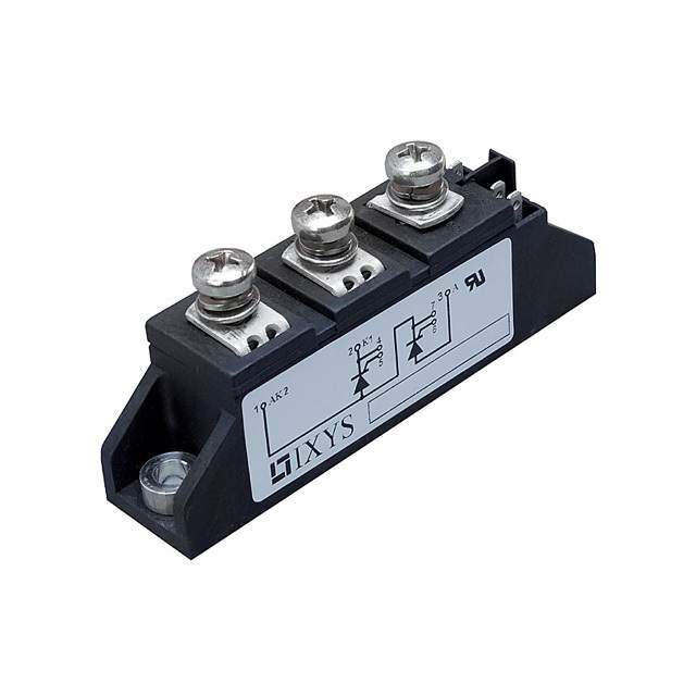
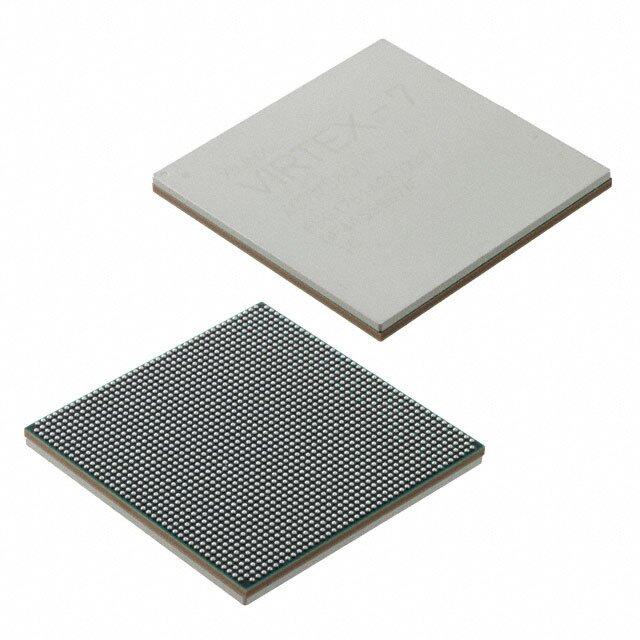
IXYS(现属Littelfuse)的MCD72-08IO8B是一款双反并联晶闸管(SCR)模块,额定电流72A、反向重复峰值电压800V,内置热敏电阻(NTC)和压接式封装,适用于高可靠性、中大功率交流控制场合。典型应用场景包括:
1. 工业电机软启动器:用于三相异步电机的可控相位触发启动,降低启动冲击电流与机械应力;
2. 固态继电器(SSR)与交流调功器:在加热系统(如电炉、注塑机温控)、照明调光中实现无触点、长寿命的功率调节;
3. 无功补偿装置(SVC):配合电容器组,通过过零或相控方式投切,动态补偿电网无功功率;
4. UPS与逆变电源的旁路/切换电路:在主电源故障时快速、可靠地切换至备用路径;
5. 电焊设备中的主回路整流/逆变控制:尤其适用于可控整流型弧焊电源的输出调节。
该模块具备高di/dt耐受能力、低通态压降及优异热循环性能,适合工作环境较严苛(如高温、振动)的工业现场。需搭配匹配的驱动电路(如脉冲变压器或专用SCR驱动IC)、散热器及过压/过流保护(RC缓冲、快速熔断器)以确保长期稳定运行。
| 参数 | 数值 |
| 产品目录 | |
| 描述 | MOD THYRISTOR/DIO 800V TO-240AA分立半导体模块 72 Amps 800V |
| 产品分类 | SCR - 模块分离式半导体 |
| GateTriggerCurrent-Igt | 150 mA |
| 品牌 | IXYS |
| 产品手册 | |
| 产品图片 |
|
| rohs | 符合RoHS无铅 / 符合限制有害物质指令(RoHS)规范要求 |
| 产品系列 | 分立半导体模块,IXYS MCD72-08io8B- |
| 数据手册 | |
| 产品型号 | MCD72-08io8B |
| SCR数,二极管 | 1 SCR,1 个二极管 |
| 产品 | Thyristor Power Modules |
| 产品种类 | 分立半导体模块 |
| 保持电流Ih最大值 | 200 mA |
| 其它名称 | MCD7208IO8B |
| 其它有关文件 | |
| 包装 | 散装 |
| 反向电压 | 800 V |
| 商标 | IXYS |
| 安装类型 | 底座安装 |
| 安装风格 | Screw |
| 封装 | Bulk |
| 封装/外壳 | TO-240AA |
| 封装/箱体 | TO-240 AA |
| 工作温度 | - 40 C to + 100 C |
| 工厂包装数量 | 6 |
| 栅极触发电流-Igt | 150 mA |
| 标准包装 | 6 |
| 正向电压下降 | 1.34 V |
| 电压-断态 | 800V |
| 电流-不重复浪涌50、60Hz(Itsm) | 1700A,1800A |
| 电流-保持(Ih)(最大值) | 200mA |
| 电流-栅极触发(Igt)(最大值) | 150mA |
| 电流-通态(It(AV))(最大值) | 115A |
| 电流-通态(It(RMS))(最大值) | 180A |
| 类型 | Phase Leg Thyristor Modules |
| 系列 | MCD72 |
| 结构 | 串联 - SCR/二极管 |


- 商务部:美国ITC正式对集成电路等产品启动337调查
- 曝三星4nm工艺存在良率问题 高通将骁龙8 Gen1或转产台积电
- 太阳诱电将投资9.5亿元在常州建新厂生产MLCC 预计2023年完工
- 英特尔发布欧洲新工厂建设计划 深化IDM 2.0 战略
- 台积电先进制程称霸业界 有大客户加持明年业绩稳了
- 达到5530亿美元!SIA预计今年全球半导体销售额将创下新高
- 英特尔拟将自动驾驶子公司Mobileye上市 估值或超500亿美元
- 三星加码芯片和SET,合并消费电子和移动部门,撤换高东真等 CEO
- 三星电子宣布重大人事变动 还合并消费电子和移动部门
- 海关总署:前11个月进口集成电路产品价值2.52万亿元 增长14.8%


PDF Datasheet 数据手册内容提取
MCC 72 MCD 72 Thyristor Modules I = 2x180 A TRMS Thyristor/Diode Modules I = 2x115 A TAVM V = 800-1800 V RRM V V Type TO-240 AA 6 RSM RRM 3 7 V V 2 4 DSM DRM 1 5 V V Version 1 B 8 B Version 1 B 8 B 900 800 MCC 72-08 io1 B /io8 B MCD 72-08 io1 B /io8 B 1300 1200 MCC 72-12 io1 B /io8 B MCD 72-12 io1 B /io8 B 1500 1400 MCC 72-14 io1 B /io8 B MCD 72-14 io1 B /io8 B 1700 1600 MCC 72-16 io1 B /io8 B MCD 72-16 io1 B /io8 B 1900 1800 MCC 72-18 io1 B /io8 B MCD 72-18 io1 B /io8 B Symbol Conditions Maximum Ratings 3 6 7 1 5 4 2 I , I T = T 180 A TRMS FRMS VJ VJM MCC I , I T = 63°C; 180° sine 115 A TAVM FAVM C Version 1 B T = 85°C; 180° sine 85 A C I , I T = 45°C t = 10 ms (50 Hz), sine 1700 A 3 1 5 4 2 TSM FSM VJ V = 0 t = 8.3 ms(60 Hz), sine 1800 A R MCD T = T t = 10 ms (50 Hz), sine 1540 A VJ VJM Version 1 B V = 0 t = 8.3 ms(60 Hz), sine 1640 A R ∫∫∫∫∫i2dt TVJ = 45°C t = 10 ms (50 Hz), sine 14 450 A2s 3 6 1 5 2 V = 0 t = 8.3 ms(60 Hz), sine 13 500 A2s R MCC TVJ = TVJM t = 10 ms (50 Hz), sine 11 850 A2s Version 8 B V = 0 t = 8.3 ms(60 Hz), sine 11 300 A2s R (di/dt) T = T repetitive, I = 250 A 150 A/µs 3 1 5 2 cr VJ VJM T f = 50 Hz; t =200 µs P MCD V = 2/ V Version 8 B D 3 DRM I = 0.45 A non repetitive, I = I 500 A/µs G T TAVM diG/dt = 0.45 A/µs Features (dv/dt)cr TVJ = TVJM; VDR = 2/3 VDRM 1000 V/µs (cid:129)International standard package, RGK = ∞; method 1 (linear voltage rise) JEDEC TO-240 AA PGM TVJ = TVJM; tP = 30 µs 10 W (cid:127)Direct copper bonded Al2O3 -ceramic I = I ; t = 300 µs 5 W base plate T TAVM P (cid:127)Planar passivated chips P 0.5 W GAV (cid:127)Isolation voltage 3600 V~ V 10 V (cid:127)UL registered, E 72873 RGM (cid:127)Gate-cathode twin pins for version 1B T -40...+125 °C VJ T 125 °C VJM Applications T -40...+125 °C stg (cid:127)DC motor control V 50/60 Hz, RMS; t = 1 min 3000 V~ ISOL (cid:127)Softstart AC motor controller I ≤ 1 mA; t = 1 s 3600 V~ ISOL (cid:127)Light, heat and temperature control M Mounting torque (M5) 2.5-4.0/22-35 Nm/lb.in. d Terminal connection torque (M5) 2.5-4.0/22-35 Nm/lb.in. Advantages Weight Typical including screws 90 g (cid:127)Space and weight savings (cid:127)Simple mounting with two screws Data according to IEC 60747 and refer to a single thyristor/diode unless otherwise stated. (cid:127)Improved temperature and power cycling (cid:127)Reduced protection circuits 9 IXYS reserves the right to change limits, test conditions and dimensions 41 © 2004 IXYS All rights reserved 1 - 4
MCC 72 MCD 72 Symbol Conditions Characteristic Values I , I T = T ; V = V ; V = V 5 mA RRM DRM VJ VJM R RRM D DRM V /V I /I = 300 A; T = 25°C 1.74 V T F T F VJ V For power-loss calculations only (T = 125°C) 0.85 V T0 VJ r 3.2 mΩ T V V = 6 V; T = 25°C 2.5 V GT D VJ T = -40°C 2.6 V VJ I V = 6 V; T = 25°C 150 mA GT D VJ T = -40°C 200 mA VJ V T = T ; V = 2/ V 0.2 V GD VJ VJM D 3 DRM I 10 mA GD I T = 25°C; t = 10 µs; V = 6 V 450 mA L VJ P D I = 0.45 A; di /dt = 0.45 A/µs G G I T = 25°C; V = 6 V; R = ∞ 200 mA H VJ D GK t T = 25°C; V = ½ V 2 µs gd VJ D DRM I = 0.45 A; di /dt = 0.45 A/µs G G t T = T ; I = 150 A, t = 200 µs; -di/dt = 10 A/µs typ. 185 µs Fig. 1 Gate trigger characteristics q VJ VJM T P V = 100 V; dv/dt = 20 V/µs; V = 2/ V R D 3 DRM Q T = T ; I /I = 50 A, -di/dt = 6 A/µs 170 µC S VJ VJM T F I 45 A RM R per thyristor/diode; DC current 0.3 K/W thJC per module other values 0.15 K/W R per thyristor/diode; DC current see Fig. 8/9 0.5 K/W thJK per module 0.25 K/W d Creepage distance on surface 12.7 mm S d Strike distance through air 9.6 mm A a Maximum allowable acceleration 50 m/s2 Optional accessories for module-type MCC 72 version 1 B Keyed gate/cathode twin plugs with wire length = 350 mm, gate = yellow, cathode = red Type ZY 200L(L = Left for pin pair 4/5) UL 758, style 1385, Type ZY 200R(R = right for pin pair 6/7) CSA class 5851, guide 460-1-1 Fig. 2 Gate trigger delay time Dimensions in mm (1 mm = 0.0394") MCC / MCD Version 1 B MCC Version 8 B MCD Version 8 B 9 IXYS reserves the right to change limits, test conditions and dimensions 41 2 - 4 © 2004 IXYS All rights reserved
MCC 72 MCD 72 Fig. 3 Surge overload current Fig. 4 ∫i2dt versus time (1-10 ms) Fig. 4a Maximum forward current I , I : Crest value, t: duration at case temperature TSM FSM Fig. 5 Power dissipation versus on- state current and ambient temperature (per thyristor or diode) Fig. 6 Three phase rectifier bridge: Power dissipation versus direct output current and ambient temperature 9 IXYS reserves the right to change limits, test conditions and dimensions 41 © 2004 IXYS All rights reserved 3 - 4
MCC 72 MCD 72 Fig. 7 Three phase AC-controller: Power dissipation versus RMS output current and ambient temperature Fig. 8 Transient thermal impedance junction to case (per thyristor or diode) R for various conduction angles d: thJC d R (K/W) thJC DC 0.3 180° 0.31 120° 0.33 60° 0.35 30° 0.37 Constants for Z calculation: thJC i R (K/W) t (s) thi i 1 0.008 0.0019 2 0.054 0.047 3 0.238 0.3 Fig. 9 Transient thermal impedance junction toheatsink(perthyristor or diode) R for various conduction angles d: thJK d R (K/W) thJK DC 0.5 180° 0.51 120° 0.53 60° 0.55 30° 0.57 Constants for Z calculation: thJK i R (K/W) t (s) thi i 1 0.008 0.0019 2 0.054 0.047 3 0.238 0.3 4 0.2 1.25 9 IXYS reserves the right to change limits, test conditions and dimensions 41 4 - 4 © 2004 IXYS All rights reserved