ICGOO在线商城 > 集成电路(IC) > PMIC - AC-DC 转换器,离线开关 > MC33364DG
- 型号: MC33364DG
- 制造商: ON Semiconductor
- 库位|库存: xxxx|xxxx
- 要求:
| 数量阶梯 | 香港交货 | 国内含税 |
| +xxxx | $xxxx | ¥xxxx |
查看当月历史价格
查看今年历史价格
MC33364DG产品简介:
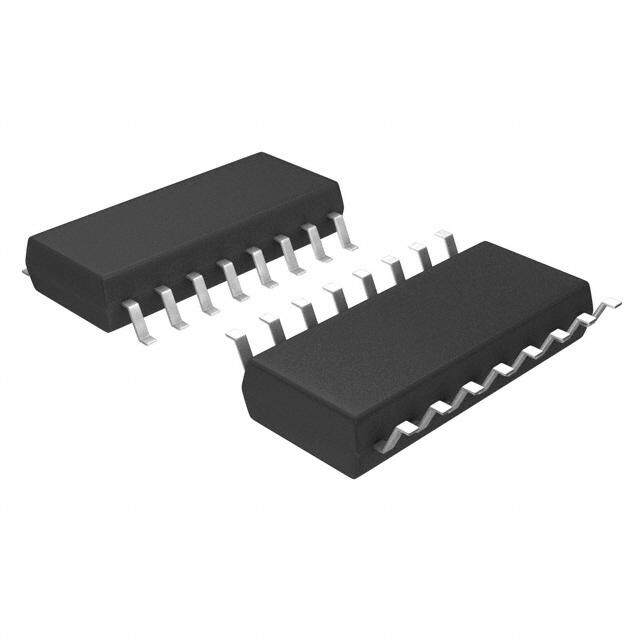
ICGOO电子元器件商城为您提供MC33364DG由ON Semiconductor设计生产,在icgoo商城现货销售,并且可以通过原厂、代理商等渠道进行代购。 MC33364DG价格参考。ON SemiconductorMC33364DG封装/规格:PMIC - AC-DC 转换器,离线开关, Converter Offline Flyback Topology 126kHz 16-SOIC。您可以下载MC33364DG参考资料、Datasheet数据手册功能说明书,资料中有MC33364DG 详细功能的应用电路图电压和使用方法及教程。
| 参数 | 数值 |
| 产品目录 | 集成电路 (IC)半导体 |
| 描述 | IC CTRLR SMPS OTP UVLO 16SOIC开关控制器 Variable Frequency SMPS |
| 产品分类 | |
| 品牌 | ON Semiconductor |
| 产品手册 | |
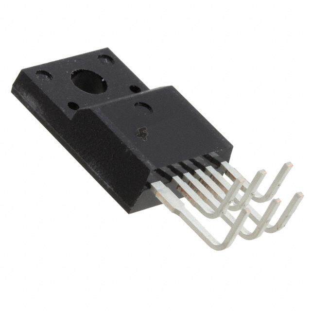
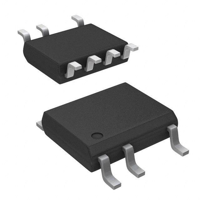
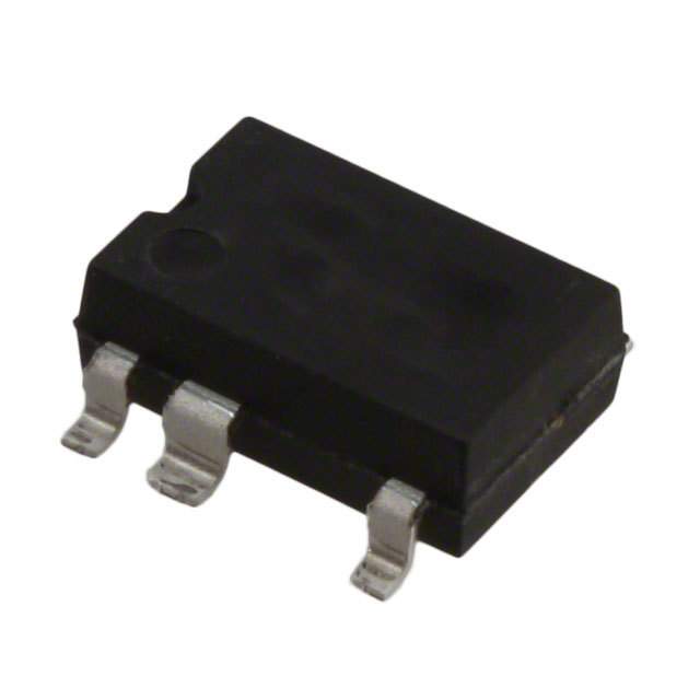
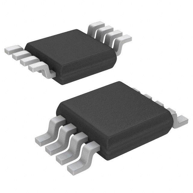
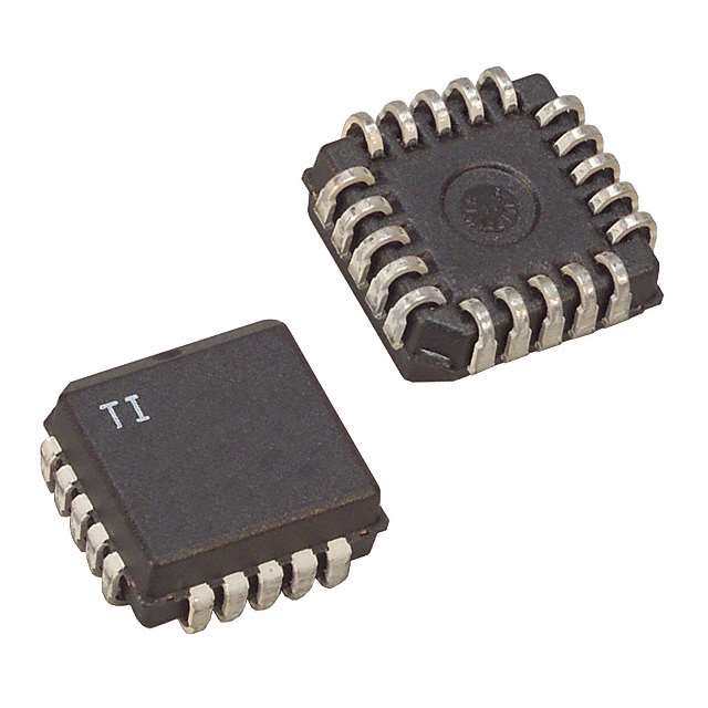
| 产品图片 |
|
| rohs | 符合RoHS无铅 / 符合限制有害物质指令(RoHS)规范要求 |
| 产品系列 | 电源管理 IC,开关控制器 ,ON Semiconductor MC33364DGGreenLine™ |
| 数据手册 | |
| 产品型号 | MC33364DG |
| 上升时间 | 67 ns |
| 下降时间 | 28 ns |
| 产品种类 | 开关控制器 |
| 供应商器件封装 | 16-SOIC N |
| 其它名称 | MC33364DGOS |
| 功率(W) | - |
| 包装 | 管件 |
| 商标 | ON Semiconductor |
| 安装风格 | SMD/SMT |
| 封装 | Tube |
| 封装/外壳 | 16-SOIC(0.154",3.90mm 宽)14 引线 |
| 封装/箱体 | SOIC-16 |
| 工作温度 | -25°C ~ 125°C |
| 工作电源电压 | 16 V |
| 工厂包装数量 | 48 |
| 拓扑结构 | Flyback |
| 最大工作温度 | + 125 C |
| 最小工作温度 | - 25 C |
| 标准包装 | 48 |
| 电压-击穿 | 700V |
| 电压-输入 | 8.5 V ~ 16 V |
| 电压-输出 | - |
| 类型 | Current Mode PWM Controllers |
| 系列 | MC33364 |
| 输出电压 | 4.90 V to 5.20 V |
| 输出电流 | 600 mA |
| 输出端数量 | 1 Output |
| 输出隔离 | 隔离 |
| 频率范围 | 104kHz ~ 800kHz |




- 商务部:美国ITC正式对集成电路等产品启动337调查
- 曝三星4nm工艺存在良率问题 高通将骁龙8 Gen1或转产台积电
- 太阳诱电将投资9.5亿元在常州建新厂生产MLCC 预计2023年完工
- 英特尔发布欧洲新工厂建设计划 深化IDM 2.0 战略
- 台积电先进制程称霸业界 有大客户加持明年业绩稳了
- 达到5530亿美元!SIA预计今年全球半导体销售额将创下新高
- 英特尔拟将自动驾驶子公司Mobileye上市 估值或超500亿美元
- 三星加码芯片和SET,合并消费电子和移动部门,撤换高东真等 CEO
- 三星电子宣布重大人事变动 还合并消费电子和移动部门
- 海关总署:前11个月进口集成电路产品价值2.52万亿元 增长14.8%


PDF Datasheet 数据手册内容提取
MC33364 Critical Conduction GreenLinet SMPS Controller TheMC33364seriesarevariablefrequencySMPScontrollersthat operateinthecriticalconductionmode.Theyareoptimizedforhigh density power supplies requiring minimum board area, reduced http://onsemi.com componentcount,andlowpowerdissipation.Integrationofthehigh voltagestartupsavesapproximately0.7Wofpowercomparedtothe MARKING valueoftheresistorbootstrappedcircuits. DIAGRAMS EachMC33364featuresanon--boardreference,UVLOfunction,a 8 watchdogtimertoinitiateoutputswitching,azerocurrentdetectorto ensure critical conduction operation, a current sensing comparator, SO--8 M64Dx D1,D2SUFFIX ALYW leading edge blanking, a CMOS driver and cycle--by--cycle current 8 CASE751 G limiting. 1 1 The MC33364D1 has an internal 126 kHz frequency clamp. The MC33364D2 is available without an internal frequency clamp. The MC33364Dhasaninternal126kHzfrequencyclampwhichispinned 16 out,sothatthedesignercanadjusttheclampfrequencybyconnecting SO--16 appropriatevaluesofresistance. DSUFFIX MC33364D 16 CASE751K AWLYWWG Features 1 1 LosslessOff--LineStartup LeadingEdgeBlankingforNoiseImmunity x =1or2 A =AssemblyLocation WatchdogTimertoInitiateSwitching WL =WaferLot OperatingTemperatureRange--25Cto+125C Y =Year ShutdownCapability W,WW =WorkWeek GorG =Pb--FreePackage OverTemperatureProtection Optional/AdjustableFrequencyClamptoLimitEMI ThisisaPb--FreeandHalide--FreeDevice PINCONNECTIONS MC33364D1 ORDERINGINFORMATION MC33364D2 Device Package Shipping† ZeroCurrent 1 8 Line MC33364D1G 96Units/Rail CurrentSense 2 7 VCC MC33364D1R2G SO--8 2500Units/Tape&Reel VoltageFB 3 6 GateDrive MC33364D2G (Pb--Free) 96Units/Rail Vref 4 5 GND MC33364D2R2G 2500Units/Tape&Reel (TopView) MC33364DG SO--16 48Units/Rail MC33364D (Pb--Free) MC33364DR2G 2500Units/Tape&Reel ZeroCurrent 1 16 Line †Forinformationontapeandreelspecifications,includingpartorientation andtapesizes,pleaserefertoourTapeandReelPackagingSpecifications N/C 2 Brochure,BRD8011/D. CurrentSense 3 VoltageFB 4 13 N/C N/C 5 12 Vcc Vref 6 11 GateDrive N/C 7 10 PGND FreqClamp 8 9 AGND (TopView) SemiconductorComponentsIndustries,LLC,2010 1 PublicationOrderNumber: November,2010--Rev.18 MC33364/D
MC33364 Vref Vcc Line Vrefregulator Startup Vref Vcc turnon UVLO + turnon -- UVLO + 15V/8.1V -- ZCD -- 15V/7.6V + Vref UVLO 10V 1.2V/1.0V + Thermal -- 5k Shutdown Reset 15V/var 45k 15k Watchdog FB Timer Vcc R R Q Level Gate -- S SNA CS LEB + PGnd 0.1V AGnd FC FrequencyClamp Figure1.RepresentativeBlockDiagram Input ACVoltage Output Voltage MC33364D ZCD Line CS FB Vcc Vref Drive Rsense PGnd FC AGnd R1 R2 Figure2.TypicalApplicationCircuit http://onsemi.com 2
MC33364 Startupcircuitis Startupcircuitturns chargingtheVCC offwhenVCCis15V capacitor 15V SupplyVoltage,VCC 8.1V VT(3.5to6V) 5V Startupcircuitturns onwhenVCCreaches ReferenceVoltage,Vref thethresholdVT 0V Vrefregulatorturnson whenVCCreaches15V VreffallsfasterthanVCC Vrefregulatorturns sinceVrefcapacitorismuch offwhenVCCfalls smallerthanVCCcapacitor below8.1V Maximumdraincurrentis limitedto1.15V/Rsense DrainCurrent 0A Switchingstartswhen Switchingstopswhen Vrefreaches5V Vreffallsbelow3.7V Figure3.TimingDiagraminFaultCondition CriticialMode DiscontinousConductionMode Output Noload Current Maximumdraincurrentislimitedto1.15V/Rsense Drain LEB Current toff(min) Secondary SideDiode Current Vin Drain Voltage 10V Voltage atZCD 0.7V ZCDisignoredduringminimumoff--timelimit Figure4.TimingDiagraminNormalCondition http://onsemi.com 3
MC33364 PINDESCRIPTION Pin Function Description 1(1) ZeroCurrentDetect TheZCDPinensurescriticalconductionmode.ZCDmonitorsthevoltageontheauxiliarywinding, duringthedemagnetizationphaseofthetransformer,comparingittoaninternalreference.The ZCDsetsthelatchfortheoutputdriver. 3(2) CurrentSense TheCurrentSensePinmonitorsthecurrentinthepowerswitchbymeasuringthevoltageacross aresistor.LeadingEdgeBlankingisutilizedtopreventfalsetriggering.Thevoltageiscomparedto aresistordividerconnectedtotheVoltageFeedbackPin.A110mVvoltageoff--setisappliedto compensatethenaturaloptocouplersaturationvoltage. 4(3) VoltageFeedback TheVoltageFeedbackPinistypicallyconnectedtothecollectoroftheoptocouplerforfeedback fromtheisolatedsecondaryoutput.TheFeedbackisconnectedtotheVrefPinviaa5kresistor providingbiasfortheexternaloptocoupler. 6(4) Vref TheVrefPinisabufferedinternal5.0VreferencewithUndervoltageLockout. 8(NA) FrequencyClamp TheFrequencyClampPinensuresaminimumoff--timevalue,typically6.9ms.Itpreventsthe MOSFETfromrestartingwithinafixed(33364D1)oradjustable(33364D)delay.Theminimum off--timeisdisabledinthe33364D2.Thereforethemaximumswitchingfrequencycannotexceed 1/(TON+TOFFmin). 9(5) AGND Thispinisthegroundfortheinternalcircuitryexcludingthegatedrivestage. 10(5) PGND Thispinisthegroundforthegatedrivestage. 11(6) GateDrive ThegatedriveistheoutputtodrivethegateofthepowerMOSFET. 12(7) VCC ProvidesthevoltageforallinternalcircuitryincludingthegatedrivestageandVref.Thispinhas UndervoltageLockoutwithhysteresis. 16(8) Line TheLinePinprovidestheinitialpowertotheVCCpins.Internallythelinepinisahighvoltage currentsource,eliminatingtheneedforanexternalstartupnetwork. NOTE: ForfurtherinformationpleaserefertothefollowingApplicationNotes; AN1594:CriticalConductionMode,FlybackSwitchingPowerSupplyUsingtheMC33364. AN1681:HowtokeepaFlybackSwitch--ModePowerSupplyStablewithaCritical--ModeController. MAXIMUMRATINGS(TA=25C,unlessotherwisenoted.) Rating Symbol Value Unit PowerSupplyVoltage(Operating) VCC 16 V LineVoltage VLine 700 V CurrentSense,Compensation, Vin1 --1.0to+10 V VoltageFeedback,RestartDelayandZeroCurrentInputVoltage ZeroCurrentDetectInput Iin 5.0 mA RestartDiodeCurrent Iin 5.0 mA PowerDissipationandThermalCharacteristics D1andD2Suffix,PlasticPackageCase751 MaximumPowerDissipation@TA=70C PD 450 mW ThermalResistance,Junction--to--Air RθJA 178 C/W DSuffix,PlasticPackageCase751B--05 MaximumPowerDissipation@TA=70C PD 550 mW ThermalResistance,Junction--to--Air RθJA 145 C/W OperatingJunctionTemperature TJ 150 C OperatingAmbientTemperature TA --25to+125 C StorageTemperatureRange Tstg --55to+150 C StressesexceedingMaximumRatingsmaydamagethedevice.MaximumRatingsarestressratingsonly.Functionaloperationabovethe RecommendedOperatingConditionsisnotimplied.ExtendedexposuretostressesabovetheRecommendedOperatingConditionsmayaffect devicereliability. NOTE: ESDdataavailableuponrequest. http://onsemi.com 4
MC33364 ELECTRICALCHARACTERISTICS(VCC=15.5V,fortypicalvaluesTA=25C,formin/maxvaluesTJ=--25to125C) Characteristic Symbol Min Typ Max Unit VOLTAGEREFERENCE ReferenceOutputVoltage(IOut=0mA,TJ=25C) Vref 4.90 5.05 5.20 V LineRegulation(VCC=10Vto20V) Regline -- 2.0 50 mV LoadRegulation(IOut=0mAto5.0mA) Regload -- 0.3 50 mV MaximumVrefOutputCurrent IO -- 5 -- mA ReferenceUndervoltageLockoutThreshold Vth -- 4.5 -- V ZEROCURRENTDETECTOR InputThresholdVoltage(VinDecreasing) Vth 0.9 1.0 1.1 V Hysteresis(VinDecreasing) VH -- 200 -- mV InputClampVoltage--HighState(IDET=3.0mA) VIH 9.0 10.33 12 V InputClampVoltage--LowState(IDET=--3.0mA) VIL --1.1 --0.75 0.5 CURRENTSENSECOMPARATOR InputBiasCurrent(VCS=0to2.0V) IIB --0.5 0.02 0.5 mA BuiltInOffset VIO 50 108 170 mV FeedbackPinInputRange VFB 1.1 1.24 1.4 V FeedbackPintoOutputDelay tDLY 100 232 400 ns DRIVEOUTPUT SourceResistance(Drive=0V,VGate=VCC--1.0V) ROH 10 36 70 Ω SinkResistance(Drive=VCC,VGate=1.0V) ROL 5 11 25 Ω OutputVoltageRiseTime(25%--75%)(CL=1.0nF) tr -- 67 150 ns OutputVoltageFallTime(75%--25%)(CL=1.0nF) tf -- 28 50 ns OutputVoltageinUndervoltage(VCC=7.0V,ISink=1.0mA) VO(UV) -- 0.01 0.03 V LEADINGEDGEBLANKING DelaytoCurrentSenseComparatorInput tPHL(in/out) -- 250 -- ns (VFB=2.0V,VCS=0Vto4.0Vstep,CL=1.0nF) THERMALSHUTDOWN Shutdown(JunctionTemperatureIncreasing) Tsd -- 180 -- C Hysteresis(JunctionTemperatureDecreasing) TH -- 50 -- TIMER WatchdogTimer tDLY 200 360 700 ms UNDERVOLTAGELOCKOUT StartupThreshold(VCCIncreasing) Vth(on) 14 15 16 V MinimumOperatingVoltageAfterTurn--On(VCCDecreasing) VShutdown 6.5 7.6 8.5 V FREQUENCYCLAMP InternalFCFunction(pinopen) fmax 104 126 145 kHz InternalFCFunction(pingrounded) fmax 400 564 800 kHz FrequencyClampInputThreshold Vth(FC) 1.89 1.95 2.01 V FrequencyClampControlCurrentRange(Sink) IControl 30 70 110 mA DeadTime(FCpin=1.7V) Td 3.5 5.0 6.5 ms TOTALDEVICE LineStartupCurrent(VLine=50V)(VCC=Vth(on)--1.0V) ILine 5.0 8.5 12 mA RestartDelayTime tDLY 100 ms LinePinLeakage(VLine=500V) ILine 0.5 32 70 mA LineStartupCurrent(VCC=0V,VLine=50V) ILine 6.0 10 12 mA VCCDynamicOperatingCurrent(50kHz,CL=1.0nF) ICC 1.5 2.75 4.5 mA VCCOffStateConsumption(VCC=11V) ICCOff 300 544 800 mA http://onsemi.com 5
MC33364 30 500 VCC=14V s) 25 CL=1000pF ( V) 20 TA=25C ELAY 450 OLTAGE( 15 GTIMED 400 VCC=15V V O UT 10 HD P C OUT 5.0 WAT 350 ,Y 0 DL t --5.0 300 --55 --25 0 25 50 75 100 125 5.0ms/DIV TA,AMBIENTTEMPERATURE(C) Figure5.DriveOutputWaveform Figure6.WatchdogTimerDelay versusTemperature 6.0 1000 E mA) ANC W) DSuffix RRENT( 4.0 CircuitofFigure RESISTAIR(C/ 16PinSOIC UPPLYCU 2.0 1T2A=25C THERMAL TION--TO--100 ,SC ,A(t)UNC C JJ I R 0 10 4.0 6.0 8.0 10 12 14 16 0.01 0.1 1.0 10 100 VCC,SUPPLYVOLTAGE(V) t,TIME(s) Figure7.SupplyCurrent Figure8.TransientThermalResistance versusSupplyVoltage 40 1.4 FC--to--Vref 35 1.2 E DSuffix s)m 30 TAG 1.0 16PinSOIC E( OL 0.8 TA=25C TIM 25 EV VCC=15V OFF-- 20 SENS 00..46 M T U 15 N M E 0.2 MINI 10 URR 0 C FC--to--Gnd 5 --0.2 0 --0.4 10 100 1000 0 0.5 1.0 1.5 2.0 2.5 3.0 3.5 4.0 4.5 5.0 5.5 6.0 RESISTOR(kΩ) FEEDBACKVOLTAGE Figure9.MinimumOff--timeversusTimingResistor Figure10.FeedbackVoltageversus ontheFCPin CurrentSenseVoltage http://onsemi.com 6
MC33364 OPERATINGDESCRIPTION Introduction this case. Figure 3 shows the timing diagram in a fault The MC33364 series represents a variable--frequency condition. There are three Under--Voltage Lock--Out current--modecritical--conductionsolutionwithintegrated (UVLO) thresholds with respect to V . The upper CC highvoltagestartupandprotectioncircuitrytoimplementan threshold is 15V. When this limit is reached, the startup off--lineflybackconverterformodernconsumerelectronic circuit block turns off and V declines due to power CC power supplies. Different frequency clamp options offer consumptionofthecircuitry.Thestartupcircuitblockturns differentcustomizedneeds.Thisdeviceseriesincludesan onwhenV reaches7.6VandifV ishigherthan3.7V. CC ref integrated 700V Very High--Voltage (VHV) start--up It is the second threshold of V . If V is smaller than CC ref circuit. Thus, it is possible to design an application with 3.7V,thestartupcircuitwillturnonwhenV reachesa CC universalinputvoltagefrom85Vacto265Vacwithoutany temperaturedependentvalueV rangingbetween3.5Vand T additionalstartupcircuitsorcomponents. 6V. It is the last threshold of V . This temperature CC Thecriticalconductionfeatureofferssomeadvantages. dependentthresholdislowerwhentemperatureishigherso First,theMOSFETturnsonatzerocurrentandthediode thatittakesalongertimetorestoretheV .Itisaprotection CC turns off at zero current. The zero current reduces these feature, which allows more dead time for cooling in high turn--on and turn--off switching losses. It also reduces the temperaturecondition. Electro--MagneticInterface(EMI)oftheSMPSandaless ThereisanUVLOintheV regulatorblock.WhenV ref CC expensiverectifiercanbeused.Second,bypreventingthe falls below typical 8.1V in abnormal situation, the V ref SMPS from entering the discontinuous conduction mode regulatorblockstops.V andV collapsesduetopower ref CC (DCM),thepeakMOSFETdraincurrentislimitedtoonly consumptionofthecircuitry.WhenV collapsestobelow ref twicetheaverageinputcurrent.Itneedsasmallerandless 3.7V,thedevicecannotprovidetheDriveoutputandmakes expensiveMOSFET.Third,bypreventingtheSMPSfrom adeadtime.Thisdeadtimeisdesignedforminimalpower entering the Continuous Conduction Mode (CCM), the transfer in the abnormal conditions. The dead time ends flybacktopologytransferfunctionstaysfirst--orderandits whenV reaches15VafterreachingtheUVLOlimitV CC T feedbackcompensationnetworkisconsiderablysimplified. (3.5to6V).ReachingV enablesthestartupcircuitblock, T It also maximizes the power transfer by the flyback charging up the V capacitor again. When V reaches CC CC transformertoits1/2LI2limits. 15Vagain,theV regulatorblockturnsonandallowsthe ref A description of each of the functional blocks is given outputtoworkagain. below. The representative block diagram and typical Itisrecommendedtoputa0.1uFcapacitoronV pinfor ref applicationcircuitareinFigure1andFigure2. stability of the voltage buffer. The V capacitor is CC relativelylargerthanthis0.1uFcapacitor,makingalonger Line,V ,StartupCircuitandReferenceVoltage CC V chargingtimefromV to15Vandalongerdeadtime CC T TheLinepiniscapableofamaximum700Vsothatitis intheabnormalorfaultconditions. possible to connect this pin directly to the rectified high--voltage Alternating Current (AC) input for ZeroCurrentDetect minimizingthenumberofexternalcomponents.Thereisa To achieve critical conduction mode, MOSFET startupcircuitblockthatregulatesvoltagefromtheLinepin conduction is always initiated by sensing a zero current to the VCC pin in an abnormal situation. In normal signalfromtheZeroCurrentDetect(ZCD)pin.TheZCD conditions, the auxiliary winding powers up the VCC and pinindirectlymonitorstheinductorcurrentbysensingthe thisstartupcircuitisopenedandsavesapproximate0.7W auxiliarywindingvoltage.Whenthevoltagefallsbelowa ofpowercomparedtotheresistorbootstrappedcircuits. thresholdof1.0V,thecomparatorresetstheRSlatchtoturn Innormaloperation,theauxiliarywindingpowersupthe theMOSFETon.Thereis200mVofhysteresisbuiltintothe VCCvoltage.Thisvoltageisaconstantvaluebetweenthe comparatorfornoiseimmunityandtopreventfalsetripping. UVLOlimits(7.6Vand15V).Itisfurtherregulatedtoa There are 10V and 0.7V clamps in the ZCD pin for constant5VreferencevoltageVreffortheinternalcircuitry protection.Anexternalresistorisrecommendedtolimitthe usage. As long as the VCC voltage is between 7.6V and inputcurrentto2mAtoprotecttheclamps. 15V,itmeanstheauxiliarywindingcanprovidevoltageas innormalcondition.Thedevicerecognizesthatthereisno WatchdogTimer fault in the circuit and the device remains in the normal Awatchdogtimerblockisaddedtothedevicetostartor operationstatus. restarttheDriveoutputwhensomethinggoeswronginthe However, when the auxiliary winding cannot power up ZCD.Whentheinductorcurrentreacheszeroforlongerthan V ,theV voltagewillreachitsUVLOlimit.Thedevice approximate410ms,thetimerresettheRSlatchandthat CC CC turnstheMOSFETon. recognizesthatitisanabnormalsituation(suchasstartupor outputshort--circuited).TheV voltageisnotconstantin CC http://onsemi.com 7
MC33364 CurrentSenseandFeedbackRegulation FrequencyClampOptions Current--mode control is implemented with the Current The drawback of critical conduction mode is variable Sense (CS) pin and Feedback (FB) pin. The FB pin is switchingfrequency.Theswitchingfrequencycanincrease internally pulled up with a 5kOhm resistor from the 5V dramaticallytohundredsofkHzwhentheoutputcurrentis V .Thereisaresistordividercircuitanda0.1Voffsetin toolowor vanishes. Itis abig problemwhen EMI above ref thisfunctionalblock.Thefollowingequationdescribesthe 150kHzisconcerned.FrequencyClamp(FC)isanoptional relationbetweenthevoltagesoftheFBandCSpins,V featureinthedevicetolimittheupperswitchingfrequency FB andV respectively. to nominal 126kHz by inserting a minimum off--time CS (t ). When a minimum off--time is inserted, the VCS(max)=VFB∕4−0.1V off(min) maximumfrequency(f )limitisset. max Whentheoutputisshortcircuited,thereisnofeedback 1 signal from the opto coupler and the FB pin is opened. It fmax= ton(min)+toff(min) givesV =5VandthemaximumvoltageoftheCSpinis FB 1.15V.Whenthevoltageexceeds1.15V,thecurrentsense The SMPS is forced to operate in DCM when the comparator turns on and terminates the MOSFET maximumfrequencyisreached.Theminimumoff--timeis conduction. It stops current flowing through the sense immediatelycountedafterthedrivingsignalgoeslow.Ifthe resistor (R ) and hence the sense resistor limits the ZCDsignalcomeswithinthisminimumoff--time,theZCD Sense maximum MOSFET drain current by the following informationisignoreduntiltheminimumoff--timeexpires. equation. ThenextZCDsignalstartstheMOSFETconduction. There are three available FC options: MC33364D -- MaximumDrainCurrent=1.15∕Rsense adjustable minimum off--time by external resistor, Whentheoutputvoltageistoohigh,theFBpinvoltageis MC33364D1 -- 6.9us fixed minimum off--time, and pulleddownbytheoptocouplercurrentandthedutyratio MC33364D2--nominimumoff--time(FCdisable). isreduced.Theoutputvoltageisthenregulated. The MC33364D has a FC pin, which can vary the There is a Leading Edge Blanking (LEB) circuit with minimumoff--time(orthemaximumfrequency)externally 250nspropagationdelaytopreventfalsetriggeringdueto inFigure11.IftheFCpinisopened,theminimumoff--time parasiticsintheCSpin.Itmakesaminimumon--timeofthe is fixed at 6.9us. If the FC pin is grounded, the clamp is MOSFET(t ). on(min) disabled,andtheSMPSwillalwaysoperateincriticalmode. Itisgenerallynotrecommendedtosinkorsourcemorethan ThermalShutdown 80uA from the FC pin because high currents may cause Thereisathermalshutdownblocktopreventoverheating unstableoperation. condition and protect the device from overheating. When temperature is over 180_C, the Drive output and startup circuit block are disable. The device resumes operation Vref FC whentemperaturefallsbelow130_C. GateDriveOutput FC GND The IC contains a CMOS output driver specifically designed for direct drive of power MOSFET. The Drive Increasetoff Decreasetoff Output typical rise and fall times are 50ns with a 1.0nF load.UnbalancedSourceandSinkeliminatestheneedforan FC FC external resistor between the device Drive output and the GateoftheexternalMOSFET.Additionalinternalcircuitry hasbeenaddedtokeeptheDriveOutputinasinkingmode GND whenevertheUVLOisactive.Thischaracteristiceliminates toff=6.9us toff=0us theneedforanexternalgatepull--downresistor. (FCdisable) Figure11.FrequencyClampSetting http://onsemi.com 8
MC33364 APPLICATIONINFORMATION DesignExample startup switch is turned off by the undervoltage and the Design an off--line Flyback converter according to the overvoltagecontrolcircuit.Becausethepowersupplycan followingrequirements: beshortedontheoutput,causingtheauxiliaryvoltagetobe OutputPower: 12W zero,theMC33364willperiodicallystartitsstartupblock. Output: 6.0V@2Amperes Thismodeisnamed“hiccupmode”.Duringthismodethe Inputvoltagerange: 90Vac--270Vac,50/60Hz temperatureofthechiprisesbutremainsprotectedbythe The operation for the circuit shown in Figure 12 is as thermalshutdownblock.Duringthepowersupply’snormal follows: the rectifier bridge D1--D4 and the capacitor C1 operation,thehighvoltageinternalMOSFETisturnedoff, converttheaclinevoltagetodc.Thisvoltagesuppliesthe preventing wasted power, and thereby, allowing greater primary winding of the transformer T1 and the startup circuitefficiency. circuitinU1throughthelinepin.Theprimarycurrentloop Sinceabridgerectifierisused,theresultingminimumand isclosedbythetransformer’sprimarywinding,theTMOS maximumdcinputvoltagescanbecalculated: switchQ1andthecurrentsenseresistorR7.Theresistors R5, R6, diode D6 and capacitor C4 create a snubber Vin(min)dc=2xVin(min)ac=290Vac=127V clamping network that protects Q1 from spikes on the primarywinding.ThenetworkconsistingofcapacitorC3, Vin(max)dc=2xVin(max)ac=2270Vac=382V diodeD5andresistorR1providesaVCCsupplyvoltagefor Themaximumaverageinputcurrentis: U1 from the auxiliary winding of the transformer. The resistorR1makesV morestableandresistanttonoise. Pout 12W TheresistorR2reducCeCsthecurrentflowthroughtheinternal Iin=nVin(min)=0.8127V=0.118A clampingandprotectionzenerdiodeoftheZeroCrossing wheren=estimatedcircuitefficiency. Detector(ZCD)withinU1.C3isthedecouplingcapacitor A TMOS switch with 600 V avalanche breakdown ofthesupplyvoltage.TheresistorR3canprovideadditional voltageisused.Thevoltageontheswitch’sdrainconsistsof biascurrentfortheoptoisolator’stransistor.ThediodeD8 the input voltage and the flyback voltage of the andthecapacitorC5rectifyandfiltertheoutputvoltage.The transformer’s primary winding. There is a ringing on the TL431, a programmable voltage reference, drives the risingedge’stopoftheflybackvoltageduetotheleakage primarysideoftheoptoisolatortoprovideisolatedfeedback inductanceofthetransformer.Thisringingisclampedbythe totheMC33364.TheresistordividerconsistingofR10and RCDnetwork.Designthisclampedwaveforanamplitude R11programthevoltageoftheTL431.TheresistorR9and of 50 V below the avalanche breakdown of the TMOS thecapacitorsC7andC8providefrequencycompensation device.Addanother50Vtoallowasafetymarginforthe ofthefeedbackloop.ResistorR8providesacurrentlimitfor MOSFET.Thenasuitablevalueoftheflybackvoltagemay theoptocouplerandtheTL431. becalculated: Sincethecriticalconductionmodeconverterisavariable frequencysystem,theMC33364hasabuilt--inspecialblock Vflbk = VTMOS − Vin(max) − 100V toreduceswitchingfrequencyinthenoloadcondition.This = 600V − 382V − 100V = 118V block is named the ”frequency clamp” block. MC33364 SincethisvalueisveryclosetotheV ,set: usedinthedesignexamplehasaninternalfrequencyclamp in(min) setto126kHz.However,optionalversionswithadisabled Vflbk = Vin(min) = 127V or variable frequency clamp are available. The frequency TheV valueofthedutycycleisgivenby: flbk clampworksasfollows:theclampcontrolsthepartofthe switchingcyclewhentheMOSFETswitchisturnedoff.If Vflbk 127V ∂max= = =0.5 this ”off--time” (determined by the reset time of the Vflbk+Vin(min) [127V+127V] transformer’score)istooshort,thenthefrequencyclamp doesnotallowtheswitchtoturn--onagainuntilthedefined Themaximuminputprimarypeakcurrent: frequencyclamptimeisreached(i.e.,thefrequencyclamp wiTllhienrseeratraedseevadertailmaed)v.antages of the MC33364’sstartup Ippk=∂2mIainx=2.000.1.518A=0.472A circuit. The startup circuit includes a special high voltage Choosethedesiredminimumfrequencyf ofoperation min switch that controls the path between the rectified line tobe70kHz. voltage and the V supply capacitor to charge that CC Afterreviewingthecoresizinginformationprovidedby capacitorbyalimitedcurrentwhenthepowerisappliedto a core manufacturer, a EE core of size about 20 mm was the input. After a few switching cycles the IC is supplied chosen. Siemens’ N67 magnetic material is used, which from the transformer’s auxiliary winding. After V CC correspondstoaPhilips3C85orTDKPC40material. reaches the undervoltage lockout threshold value, the http://onsemi.com 9
MC33364 Theprimaryinductancevalueisgivenby: Theapproximatevalueofrectifiercapacitanceneededis: ∂maxVin(min) 0.5127V toff(Iin) (5msec)(0.118A) Lp= I f =0.472A70kHz=1.92mH C1=Vripple= 50V =11.8mF ppk min wheretheminimumripplefrequencyis2timesthe50Hz Themanufacturerrecommendsforthatmagneticcorea linefrequencyandt ,thedischargetimeofC1duringthe maximumoperatingfluxdensityof: off haversinecycle,isassumedtobehalfthecycleperiod. Bmax=0.2T Because we have a variable frequency system, all the Thecross--sectionalareaA oftheEF20coreis: calculationsforthevalueoftheoutputfiltercapacitorswill c bedoneatthelowestfrequency,sincetheripplevoltagewill 2 Ac=33.5mm be greatest at this frequency. When selecting the output Theoperatingfluxdensityisgivenby: capacitorselectacapacitorwithlowESRtominimizeripple LpIppk fromthecurrentripple.Theapproximateequationforthe Bmax= NpAc outputcapacitancevalueisgivenby: Iout 2A From this equation the number of turns of the primary C5= = =286mF (f )(V ) (70kHz)(0.1V) windingcanbederived: min rip LpIppk Determiningthevalueofthecurrentsenseresistor(R7), np=BmaxAc oSnineceusweisththinethpeeaIkCcthuerrreenistainlimthietaptiroendeosfitghnecvoonltsaigdeerfaotriothne. TheALfactorisdeterminedby: current sensing, which is set to 1.2 V, the design of the 2 currentsenseresistorissimplygivenby: Lp LpBmaxAc AL=n2p= 2 R7=IVpcpsk=0.14.722VA=2.54Ω≈2.2Ω Lp Ippk TheerroramplifierfunctionisprovidedbyaTL431onthe secondary,connectedtotheprimarysideviaanoptoisolator, 2 theMOC8102. 0.2T33.5E--6m2 The voltage of the optoisolator collector node sets the = =105nH 2 peakcurrentflowingthroughthepowerswitchduringeach .00192H0.472A cycle.Thispinwillbeconnectedtothefeedbackpinofthe Fromthemanufacturer‘scataloguerecommendationthe MC33364,whichwilldirectlysetthepeakcurrent. corewithanA of100nHisselected.Thedesirednumber L Startingonthesecondarysideofthepowersupply,assign ofturnsoftheprimarywindingis: the sense current through the voltage--sensing resistor 1∕2 1∕2 dividertobeapproximately0.25mA.Onecanimmediately Lp 0.00192H calculatethevalueofthelowerandupperresistor: np= AL = 100nH =139turns Vref(TL431) 2.5V The number of turns needed by the 6.0 V secondary is Rlower=R11= I =0.25mA=10k div (assumingaSchottkyrectifierisused): Vout−Vref(TL431) ns=Vs+Vfwd1–∂maxnp Rupper=R10= Idiv ∂maxVin(min) 6.0V−2.5V = =14k 0.25mA 6.0V+0.3V1−0.5139 The value of the resistor that would provide the bias = =7turns 0.5127V currentthroughtheoptoisolatorandtheTL431issetbythe minimum operating current requirements of the TL431. TheauxiliarywindingtopowerthecontrolICis16Vand This current is minimum 1.0 mA. Assign the maximum itsnumberofturnsisgivenby: currentthroughthebranchtobe5mA.Thatmakesthebias (Vaux+Vfwd)(1−∂max)np resistorvalueequalto: naux= ∂max(Vin(min)) Rbias=RS=Vout−[VrefI(TL431)+VLED] LED (16V+0.9V)(1−0.5)139 = [0.5(127V)] =19turns =6.0V−[2.5V+1.4V]=420Ω≈430Ω 5.0mA http://onsemi.com 10
MC33364 TheMOC8102hasatypicalcurrenttransferratio(CTR) Thegainexhibitedbytheopenlooppowersupplyatthe of100%with25%tolerance.WhentheTL431isfull--on, highinputvoltagewillbe: 5mA will be drawn from the transistor within the 2 MOC8102.Thetransistorshouldbeinsaturatedstateatthat time,soitscollectorresistormustbe Vinmax−Vout Ns 382V−6.0V2(7) A= = (382V)(1.2V)(139) Rcollector=VreIf−Vsat=5.05V.0−m0A.3V=940Ω (Vinmax)(Verror)(Np) LED =15.53=23.82dB Sincearesistorof5.0kisinternallyconnectedfromthe The maximum recommended bandwidth is referencevoltagetothefeedbackpinoftheMC33364,the approximately: externalresistorcanhaveahighervalue fsmin 70kHz (Rint)(Rcollector) (5.0k)(940) fc= 5 = 5 =14kHz Rext=R3=(Rint)−(Rcollector)=5.0k−940 The gain needed by the error amplifier to achieve this bandwidthiscalculatedattheratedloadbecausethatyields =1157Ω≈1200Ω thebandwidthcondition,whichis: Thiscompletesthedesignofthevoltagefeedbackcircuit. In no load condition there is only a current flowing fc 14kHz Gc=20log −A=20log −23.82dB throughtheoptoisolatordiodeandthevoltagesensedivider fph 177 onthesecondaryside. =14.14dB Theloadatthatconditionisgivenby: Thegaininabsolutetermsis: V Rnoload=(ILEDo+utIdiv) Ac=10(Gc∕20)=10(14.14∕20)=5.1 Nowthecompensationcircuitelementscanbecalculated. 6.0V = =1143Ω Theoutputresistanceofthevoltagesensedividerisgivenby (5.0mA+0.25mA) theparallelcombinationofresistorsinthedivider: Theoutputfilterpoleatnoloadis: Rin=Rupper||Rlower=10k||14k=5833Ω 1 fph=(2πRnoloadCout) R9=(Ac)(Rin)=29.75k≈30k 1 =(2π)(1143)(300mF)=0.46Hz C8= 1 =382pF≈390pF InheavyloadconditiontheI andI isnegligible.The 2π(Ac)(Rin)(fc) LED div heavyloadresistanceisgivenby: The compensation zero must be placed at or below the lightloadfilterpole: Vout 6.0V Rheavy= Iout =2.0A=3.0Ω C7= 1 =11.63mF≈10mF Theoutputfilterpoleatheavyloadofthisoutputis 2π(R9)(fpn) 1 1 fph=(2πR C )=(2π)(3)(300mF)=177Hz heavy out http://onsemi.com 11
MC33364 1N4006 D1 85to EMI 265VAC Filter D2 + C1 10mF D3 400V D4 T1 D51N4934 D8 R156 MBR340 6.0V C5 Line 300mF 2.0A R5 Vcc VccUVLO RefUVLO 47K C4 C3 Reference StartUp R6 1mF 20mF 15/7.6 47K BVufrfeefr 4.7 Restart D6 ZCD ZCD Delay MUR160 R2 22k 10V 1.2/1.0 WatchMdogC33364D VREF Timer Vcc C0.110mF R3 5k RRS Q GATE R4470 MQ1TD1N60 CurrentSense FB 1.25V (optional) R7 45k sThhuetdrmowanl PGND 2.2 R8 15k 2V Frecqlaumepncy 430 R10 0.1V CS 14k LEB 4k 10V FC AGND U3 5 1 MOC8102 4 2 C7 R9 10mF 39k C8 3 1 330pF U2 TL431 2 R11 10k Figure12.CircuitintheDesignExample http://onsemi.com 12
MC33364 Thedescribedcriticalconductionmodeflybackconverterhasthefollowingperformanceandmaximumratings: Outputpower 12W Output 12V@1Ampmax J1 Inputvoltagerange 90VAC--270VAC 1 3D1 Line 2 S380 D4 J3 J2 T1 10uF C4 9 4 1 1 400V 10uF 220 2 1 7 MBRD360 +Vout R1 D2 Gnd 1N4148 R347k C6 300uF R6 R7 R8 R4 2k7 820 18k R2 47k C51nF 100k 2 U18 7 1 D3 MURS160T3 E C D N C C 4 LI V Z 6 1 Q1 GATE MTD1N60 MC33364 C9 5 3 GND 2 100nF CS 3 1 EF R5 U3 U2 R B 2.2 MOC8102 V F 1 TL431 J4 4 3 5 R9 0.1uF 4 2 4k7 1 2 --Vout Figure13.CriticalConductionModeFlybackConverter CONVERTERTESTDATA Test Conditions Results LineRegulation Vin=120VACto240VAC,Iout=0.8A ΔV=50mV Load Vin=120VAC,Iout=0.2Ato0.8A ΔV=40mV Vin=240VAC,Iout=0.2Ato0.8A ΔV=40mV OutputRipple Vin=120VAC,Iout=0.8A ΔV=290mV Vin=240VAC,Iout=0.8A ΔV=24mV Efficiency Vin=120VAC,Iout=0.8A η=78.0% Vin=240VAC,Iout=0.8A η=79.4% PowerFactor Vin=120VAC,Iout=0.8A Pf=0.491 Vin=240VAC,Iout=0.8A Pf=0.505 Vout Vout Iout Iout Ch1:2.0V/div 2.0msec/div Ch1:2.0V/div 2.0msec/div Ch2:200mA/div Ch2:200mV/div Figure14.LoadRegulation120V Figure15.LoadRegulation240V http://onsemi.com 13
MC33364 J2 Output12V@0.8Ampmax 1 2 InputVoltageRange90--270Vac,50/60Hz R13 R12 R11 22k 82k 10k 5 VS GND 4 6 CSB CMP 3 U2 R10 5.1V 7 VCC MC33341 CTA 2 C7 0.25 33nF D8 8 DO CSA 1 R8 B2X84C5V1LT1 R9 4.7k C5 100 100mF C6 D7 1.0mF D6 1N4148 R7 MURS320T3 100 2 1 9 7 T1 5 4 3 2 F Q1 n R4 5 4 R6 0 MTD1N60E 47k 1. D5 2.2 C4 MURS 160T3 R5 U3 47k MOC8102 D3 1N4148 R1 R3 220 C2 22k 20mF 6 2 Gate CS 1 ZCD FB 3 U1 MC33364D1 7 VCC C3 C1 8 Line GND Vref 4 0.1mF 10mF 5 400V D1 B250R F1 T0.2A T1= 139Turns#28Awg,primarywinding2--3 7Turns,Bifilar2x#26Awg,outputwinding9--7 19Turns#28Awg,auxiliarywinding4--5onPhilips 1 2 EF20--3C85coregapforaprimaryinductorof1.92mH. J1 Line Figure16.UniversalInputBatteryCharger http://onsemi.com 14
MC33364 PACKAGEDIMENSIONS SO--8 D1,D2SUFFIX CASE751--07 ISSUEAJ NOTES: --X-- 1. DIMENSIONINGANDTOLERANCINGPER ANSIY14.5M,1982. A 2. CONTROLLINGDIMENSION:MILLIMETER. 3. DIMENSIONAANDBDONOTINCLUDE MOLDPROTRUSION. 4. MAXIMUMMOLDPROTRUSION0.15(0.006) 8 5 PERSIDE. 5. DIMENSIONDDOESNOTINCLUDEDAMBAR B S 0.25(0.010) M Y M PROTRUSION.ALLOWABLEDAMBAR PROTRUSIONSHALLBE0.127(0.005)TOTAL 1 INEXCESSOFTHEDDIMENSIONAT --Y-- 4 K 6. M75A1X--I0M1UTMHRMUAT7E5R1-I-A0L6CAROENDOIBTSIOONL.ETE.NEW STANDARDIS751--07. G MILLIMETERS INCHES DIM MIN MAX MIN MAX C NX45_ A 4.80 5.00 0.189 0.197 B 3.80 4.00 0.150 0.157 SEATING PLANE C 1.35 1.75 0.053 0.069 --Z-- D 0.33 0.51 0.013 0.020 G 1.27BSC 0.050BSC 0.10(0.004) H 0.10 0.25 0.004 0.010 H D M J J 0.19 0.25 0.007 0.010 K 0.40 1.27 0.016 0.050 M 0_ 8_ 0_ 8_ N 0.25 0.50 0.010 0.020 0.25(0.010) M Z Y S X S S 5.80 6.20 0.228 0.244 SOLDERINGFOOTPRINT* 1.52 0.060 7.0 4.0 0.275 0.155 0.6 1.270 0.024 0.050 SCALE6:1 mm inches *ForadditionalinformationonourPb--Freestrategyandsoldering details,pleasedownloadtheONSemiconductorSolderingand MountingTechniquesReferenceManual,SOLDERRM/D. http://onsemi.com 15
MC33364 PACKAGEDIMENSIONS SO--16 DSUFFIX CASE751K--01 ISSUEO --A-- NOTES: 1. DIMENSIONINGANDTOLERANCINGPERANSIY14.5M,1982. 2. CONTROLLINGDIMENSION:MILLIMETER. 16 9 S 3. DIMENSIONSAANDBDONOTINCLUDEMOLDPROTRUSION. B 4. MAXIMUMMOLDPROTRUSION0.15(0.006)PERSIDE. 5. DIMENSIONDDOESNOTINCLUDEDAMBARPROTRUSION. M ALLOWABLEDAMBARPROTRUSIONSHALLBE0.127(0.005) 0) M_ TOTALINEXCESSOFTHEDDIMENSIONATMAXIMUM --B-- P 01 MATERIALCONDITION. 0. ( MILLIMETERS INCHES 5 0.2 F DAIM M9.I8N0 1M0A.0X0 0M.3I6N8 0M.3A9X3 1 8 B 3.80 4.00 0.150 0.157 G C 1.35 1.75 0.054 0.068 RX45_ DF 00..3450 01..4295 00..001146 00..001499 G 1.27BSC 0.050BSC J 0.19 0.25 0.008 0.009 C K 0.10 0.25 0.004 0.009 --T-- SEATING M 0_ 7_ 0_ 7_ PLANE P 5.80 6.20 0.229 0.244 K 14XD J R 0.25 0.50 0.010 0.019 0.25(0.010) M T A S B S GreenLineisatrademarkofMotorola,Inc. ONSemiconductorand areregisteredtrademarksofSemiconductorComponentsIndustries,LLC(SCILLC).SCILLCreservestherighttomakechangeswithoutfurthernotice toanyproductsherein.SCILLCmakesnowarranty,representationorguaranteeregardingthesuitabilityofitsproductsforanyparticularpurpose,nordoesSCILLCassumeanyliability arisingoutoftheapplicationoruseofanyproductorcircuit,andspecificallydisclaimsanyandallliability,includingwithoutlimitationspecial,consequentialorincidentaldamages. “Typical”parameterswhichmaybeprovidedinSCILLCdatasheetsand/orspecificationscananddovaryindifferentapplicationsandactualperformancemayvaryovertime. All operatingparameters,including“Typicals”mustbevalidatedforeachcustomerapplicationbycustomer’stechnicalexperts. SCILLCdoesnotconveyanylicenseunderitspatent rightsnortherightsofothers. SCILLCproductsarenotdesigned,intended,orauthorizedforuseascomponentsinsystemsintendedforsurgicalimplantintothebody,orother applicationsintendedtosupportorsustainlife,orforanyotherapplicationinwhichthefailureoftheSCILLCproductcouldcreateasituationwherepersonalinjuryordeathmayoccur. ShouldBuyerpurchaseoruseSCILLCproductsforanysuchunintendedorunauthorizedapplication,BuyershallindemnifyandholdSCILLCanditsofficers,employees,subsidiaries, affiliates,anddistributorsharmlessagainstallclaims,costs,damages,andexpenses,andreasonableattorneyfeesarisingoutof,directlyorindirectly,anyclaimofpersonalinjury ordeathassociatedwithsuchunintendedorunauthorizeduse,evenifsuchclaimallegesthatSCILLCwasnegligentregardingthedesignormanufactureofthepart. SCILLCisan EqualOpportunity/AffirmativeActionEmployer. Thisliteratureissubjecttoallapplicablecopyrightlawsandisnotforresaleinanymanner. PUBLICATIONORDERINGINFORMATION LITERATUREFULFILLMENT: N.AmericanTechnicalSupport:800--282--9855TollFree ONSemiconductorWebsite:www.onsemi.com LiteratureDistributionCenterforONSemiconductor USA/Canada P.O.Box5163,Denver,Colorado80217USA Europe,MiddleEastandAfricaTechnicalSupport: OrderLiterature:http://www.onsemi.com/orderlit Phone:303--675--2175or800--344--3860TollFreeUSA/Canada Phone:421337902910 Fax:303--675--2176or800--344--3867TollFreeUSA/Canada JapanCustomerFocusCenter Foradditionalinformation,pleasecontactyourlocal Email:orderlit@onsemi.com Phone:81--3--5773--3850 SalesRepresentative http://onsemi.com MC33364/D 16
 Datasheet下载
.jpg)
