ICGOO在线商城 > MBDDT2110P
 Datasheet下载
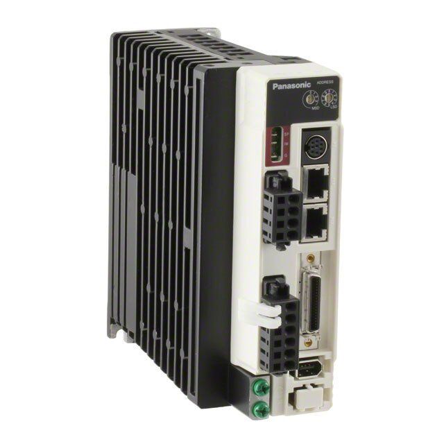
- 型号: MBDDT2110P
- 制造商: Panasonic Corporation
- 库位|库存: xxxx|xxxx
- 要求:
| 数量阶梯 | 香港交货 | 国内含税 |
| +xxxx | $xxxx | ¥xxxx |
查看当月历史价格
查看今年历史价格
MBDDT2110P产品简介:
ICGOO电子元器件商城为您提供MBDDT2110P由Panasonic Corporation设计生产,在icgoo商城现货销售,并且可以通过原厂、代理商等渠道进行代购。 提供MBDDT2110P价格参考以及Panasonic CorporationMBDDT2110P封装/规格参数等产品信息。 你可以下载MBDDT2110P参考资料、Datasheet数据手册功能说明书, 资料中有MBDDT2110P详细功能的应用电路图电压和使用方法及教程。
| 参数 | 数值 |
| 产品目录 | |
| 描述 | A4 INDEX DRIVE SINGLE PHASE |
| 产品分类 | |
| 品牌 | Panasonic Industrial Automation Sales |
| 数据手册 | |
| 产品图片 |
|
| 产品型号 | MBDDT2110P |
| rohs | 无铅 / 符合限制有害物质指令(RoHS)规范要求 |
| 产品系列 | * |
| 标准包装 | 1 |


- 商务部:美国ITC正式对集成电路等产品启动337调查
- 曝三星4nm工艺存在良率问题 高通将骁龙8 Gen1或转产台积电
- 太阳诱电将投资9.5亿元在常州建新厂生产MLCC 预计2023年完工
- 英特尔发布欧洲新工厂建设计划 深化IDM 2.0 战略
- 台积电先进制程称霸业界 有大客户加持明年业绩稳了
- 达到5530亿美元!SIA预计今年全球半导体销售额将创下新高
- 英特尔拟将自动驾驶子公司Mobileye上市 估值或超500亿美元
- 三星加码芯片和SET,合并消费电子和移动部门,撤换高东真等 CEO
- 三星电子宣布重大人事变动 还合并消费电子和移动部门
- 海关总署:前11个月进口集成电路产品价值2.52万亿元 增长14.8%


PDF Datasheet 数据手册内容提取
Technical reference AC Servo Motor & Driver MINAS A4-series •Thank you very much for your purchase of Panasonic AC Servo Motor & Driver, MINAS A4-series. •Before use, refer this technical reference and safety instructions to ensure proper use. Keep this technical reference and read when necessary. •Make sure to forward this technical reference for safety to the final user. If you are the first user of this product, please be sure to purchase and read the optional Engineering Material (DV0P4210), or downloaded Instruction Manual from our Web Site. [Web address of Motor Company, Matsushita Electric Industrial Co., Ltd.] http://industrial.panasonic.com/ww/i_e/25000/motor_fa_e/motor_fa_e.html <Contents> page page 1.Introduction.................................B2 4. Parameter..................................B27 On Opening the Package...............................B2 Outline of Parameter....................................B27 Check of the Driver Model..............................B2 How to Set....................................................B27 Check of the Motor Model..............................B3 Setup with the Front Panel...........................B27 2. Installation..................................B4 Outline of PANATERM®.......................................................B28 Driver..............................................................B4 Setup with the Console................................B28 Motor..............................................................B6 How to Connect............................................B29 Console..........................................................B8 Composition and List of Parameters............B30 3.System Configuration and 5. Protective Functions................B36 Wiring ........................................B10 Protective Function (What Is Error Code ?).....B36 6. Maintenance and Inspections.B38 Overall Wiring (Connecting Example of C-frame, 3- phase)..............................................................B10 7. Conformity to EC Directives Overall Wiring (Connecting Example of E-frame)....B12 and UL Standards.....................B40 Driver and List of Applicable Peripheral Composition of Peripheral Equipments........B41 Equipments..................................................B14 Conformity to UL Standards.........................B44 Wiring of the Main Circuit (A to D-frame) .....B16 8. Built-in Holding Brake .............B45 Wiring of the Main Circuit (E and F-frame)...B17 9. Dynamic Brake.........................B47 Wiring method to connector (A to D-frame)..B18 10. Check of the Combination of Wiring to the Connector, CN X6 the Driver and the Motor............B48 (Connection to Encoder)..............................B22 Wiring for Typical Control Modes to the Connector CN X5...............................B24 After-Sale Service (Repair)..........B51 IMC54D Z0404-6066
1. Introduction On Opening the Product Package Check of the Motor Model • Make sure that the model is what you have ordered. Contents of Name Plate • Check if the product is damaged or not during transportation. Serial Number • Check if the instruction manual is attached or not. Model CONT. TORQUE 0.64 Nm e.g.) : 04110001 AC SERVO MOTOR RATING S1 MODEL No.MSMD5AZS1S INS. CLASS B (TÜV) A (UL) • Check if the power connector and motor connecters (CN X1 and CN X2 connectors) Rated input voltage/current INPUT3ØAC 92 V IP65 Lot number 1.6 A CONNECTION are attached or not (A to D-frame). Rated output RRAATTEEDD OFRUETQPU.T2000.2 HkWz SER No. 04110001 Month of production Rated rotational speed RATED REV. 3000 r/min Year of production Contact to a dealer if you find any failures. (Lower 2 digits of AD year) Model Designation Check of the Driver Model M S M D 5 A Z S 1 S 1 to 4 5 to 6 7 8 9 10 11 to 12 Special specifications Contents of Name Plate Symbol Type (letters and numbers) Ultra low inertia Motor structure Model number AC SERVO MAMA (100W to 750W) Model No.MADDT1205 Serial No.P04110001Z Serial Number Low inertia Design order Rated input/output voltage Voltage 20IN0-P2U40TV O69UVTPUT e.g.) : P04110001Z MQMA (100W to 400W) 1: Standard Rated input/output current FFPPr.hoLeaw.qCse.er 5110.ø3/6A0Hz 0131~0ø.230A3W3.3Hz Lot number MSMD L(5o0wW in teor t7ia50W) MSyomtboolr rOatuetdp ouuttpuSytm bol Output VSyomlbtoalge spSepceifcicifaitcioantisons Month of production Low inertia Rated output of MSMA (1.0kW to 5.0kW) 5A 50W 15 1.5kW 1 100 V applicable motor Year of production Middle inertia 01 100W 20 2.0kW 2 200 V (Lower 2 digits of AD year) MDMA (1.0kW to 5.0kW) 02 200W 25 2.5kW 100/200 common MHMA High inertia 04 400W 30 3.0kW Z (50W only) (500W to 5.0kW) 05 500W 40 4.0kW Middle inertia 08 750W 45 4.5kW MFMA (400W to 4.5kW) 09 900W 50 5.0kW Middle inertia 10 1.0kW Model Designation MGMA (900W to 4.5kW) Rotary encoder specifications M A D D T 1 2 0 5 Specifications Symbol Format Pulse count Resolution Wire count 1 to 4 5 to 6 7 8 to 9 10 to 12 P Incremental 2500P/r 10,000 5-wire Special specifications S Absolute/Incremental common 17bit 131,072 7-wire (letters and numbers) Motor structure MSMD, MQMA MAMA Frame-size symbol Current detector rating Max. current Shaft Holding brake Oil seal Shaft Holding brake Oil seal Symbol Frame rating of Symbol Current rating Symbol Symbol MADD A4-series, A-frame power device Power supply 05 5A RoundKey wayWithout With Without With*1 RoundKey wayWithout With Without With A A MBDD A4-series, B-frame Symbol Current Symbol Specifications 07 7.5A B B rating MCDD A4-series, C-frame 1 Single phase, 100V 10 10A S *2 E T1 10A MDDD A4-series, D-frame 2 Single phase, 200V 15 15A T *2 F MEDD A4-series, E-frame T2 15A 3 3-phase, 200V 20 20A *1 The product with oil seal is a special order MSMA, MDMA, MFMA, MGMA, MHMA MFDD A4-series, F-frame T3 30A Single/3-phase, 30 30A product. Shaft Holding brake Oil seal T5 50A 5 200V 40 40A *2 Key way with center tap SymbolRoundKey wayWithout With Without With T7 70A C 64 64A TA 100A Products are standard stock items or build to D 90 90A order items. For details, inquire of the dealer. G TB 150A A2 120A H – B2 – – B3 –
2. Installation Install the driver and the motor properly to avoid a breakdown or an accident. E and F-frame Driver Mounting bracket Installation Place 1)Indoors, where the products are not subjected to rain or direct sun beams. The prod- ucts are not waterproof. 2)Where the products are not subjected to corrosive atmospheres such as hydrogen sulfide, sulfurous acid, chlorine, ammonia, chloric gas, sulfuric gas, acid, alkaline and salt and so on, and are free from splash of inflammable gas, grinding oil, oil mist, iron powder or chips and etc. 3)Well-ventilated and low humidity and dust-free place. Mounting Direction and Spacing 4)Vibration-free place. • Reserve enough surround- Environmental Conditions ing space for effective cool- Fan Fan 100mm ing. or more Item Conditions • Install fans to provide uni- Ambient temperature 0˚C to 55˚C (free from freezing) form distribution of tem- Ambient humidity Less than 90% RH (free from condensation) perature in the control Storage temperature –20˚C to 80˚C (free from freezing) Storage humidity Less than 90% RH (free from condensation) panel. 40mm 10omrm 10omrm 10omrm 40mm Vibration Lower than 5.9m/s2 (0.6G), 10 to 60Hz • Observe the environmental or more more more or Altitude Lower than 1000m more more conditions of the control panel described in the next 100mm How to Install page. or more 1)Rack-mount type. Install in vertical position, and reserve enough space around the servo driver for ventilation. <Note> Base mount type (rear mount) is standard (A to D-frame) It is recommended to use the conductive paint when you make your own mounting 2)Use the optional mounting bracket when you want to change the mounting face. bracket, or repaint after peeling off the paint on the machine for installing the products, in order to make noise countermeasure. A to D-frame e.g.) In case of C-frame Caution on Installation MADD MBDD Mounting bracket We have been making the best effort to ensure the highest quality, however, application MCDD (optional parts) of exceptionally large external noise disturbance and static electricity, or failure in input MDDD power, wiring and components may result in unexpected action. It is highly recommended that you make a fail-safe design and secure the safety in the operative range. There might be a chance of smoke generation due to the failure of these products. Pay an extra attention when you apply these products in a clean room environment. Fastening torque of earth screws (M4) to be 0.39 to 0.59N•m. – B4 – – B5 –
2. Installation Motor Oil/Water Protection Installation Place 1)Don't submerge the motor cable to water or oil. Cable Motor 2)Install the motor with the cable outlet facing downward. Since the conditions of location affect a lot to the motor life, select a place which meets 3)Avoid a place where the motor is subjected to oil or water. the conditions below. 4)Use the motor with an oil seal when used with the gear re- 1)Indoors, where the products are not subjected to rain or direct sun beam. The prod- ducer, so that the oil may not enter to the motor through shaft. Oil/Water ucts are not waterproof. 2)Where the products are not subjected to corrosive atmospheres such as hydrogen Stress to Cables sulfide, sulfurous acid, chlorine, ammonia, chloric gas, sulfuric gas, acid, alkaline and salt and so on, and are free from splash of inflammable gas, grinding oil, oil mist, iron 1)Avoid a stress application to the cable outlet and connecting portion by bending or powder or chips and etc. self-weight. 3)Where the motor is free from grinding oil, oil mist, iron powder or chips. 2)Especially in an application where the motor itself travels, fix the attached cable and 4)Well-ventilated and humid and dust-free place, far apart from the heat source such as contain the extension junction cable into the bearer so that the stress by bending can a furnace. be minimized. 5) Easy-to-access place for inspection and cleaning 3)Take the cable bending radius as large as possible. (Minimum R20mm) 6)Vibration-free place. 7)Avoid enclosed place. Motor may gets hot in those enclosure and shorten the motor life. Permissible Load to Output Shaft 1)Design the mechanical system so that the applied radial load and/or thrust load to the Environmental Conditions motor shaft at installation and at normal operation can meet the permissible value Item Condition specified to each model. Ambient temperature 0˚C to 40˚C (free from freezing) *1 2)Pay an extra attention when you use a rigid coupling. (Excess bending load may Ambient humidity Less than 85% RH (free from condensation) damage the shaft or deteriorate the bearing life. Storage temperature –20˚C to 80˚C (free from freezing) *2 3)Use a flexible coupling with high stiffness designed exclusively for servo application in Storage humidity Less than 85% RH (free from condensation) Vibration Motor only Lower than 49m/s2 (5G) at running, 24.5m/s2 (2.5G) at stall order to make a radial thrust caused by micro misalignment smaller than the permis- Impact Motor only Lower than 98m/s2 (10G) sible value. IP65 (except rotating portion of output shaft and lead wire end) 4)For permissible load of each model, refer to the technical reference. (DV0P4210) Enclosure •These motors conform to the test conditions specified in EN standards Motor only (EN60529, EN60034-5). Do not use these motors in application where Notes on Installation rating water proof performance is required such as continuous wash-down operation. 1)Do not apply direct impact to the shaft by hammer while attaching/detaching a cou- *1 Ambient temperature to be measured at 5cm away from the motor. pling to and from the motor shaft. *2 Permissible temperature for short duration such as transportation. (Or it may damage the encoder mounted on the other side of the shaft.) How to Install 2)Make a full alignment. (incomplete alignment may cause vibration and damage the bearing.) You can mount the motor either horizontally or vertically as long as you observe the followings. 3)If the motor shaft is not electrically grounded, it may cause 1)Horizontal mounting electrolytic corrosion to the bearing depending on the condi- Motor • Mount the motor with cable outlet facing downward for water/oil countermeasure. tion of the machine and its mounting environment, and may 2)Vertical mounting result in the bearing noise. Check and verification by customer • Use the motor with oil seal (non-standard) when mounting the motor with gear reducer to prevent the reducer oil/grease from entering to the motor. is required. 3)For mounting dimensions, refer to the technical reference. (DV0P4210) – B6 – – B7 –
2. Installation Console How to Connect Installation Place 1)Indoors, where the products are not subjected to rain or direct sun beam. The prod- ucts are not waterproof. 2)Where the products are not subjected to corrosive atmospheres such as hydrogen Connect to CN X4. sulfide, sulfurous acid, chlorine, ammonia, chloric gas, sulfuric gas, acid, alkaline and SSETMMODESHIFT salt and so on, and are free from splash of inflammable gas, grinding oil, oil mist, iron powder or chips and etc. 3)Well-ventilated and low humidity and dust-free place. 4) Easy-to-access place for inspection and cleaning Environmental Conditions Item Condition <Remarks> Ambient temperature 0˚C to 55˚C (free from freezing) • Connect the console connector securely to CN X4 connector of the driver. Ambient humidity Less than 90% RH (free from condensation) • Never pull the cable to plug in or plug out. Storage temperature –20˚C to 80˚C (free from freezing) Storage humidity Less than 90% RH (free from condensation) Vibration Lower than 5.9m/s2 (0.6G), 10 to 60Hz Conform to JISC0044 Impact (Free fall test, 1m for 2 directions, 2 cycles) Altitude Lower than 1000m <Cautions> • Do not give strong impact to the products. • Do not drop the products. • Do not pull the cables with excess force. • Avoid the place near to the heat source such as a heater or a large winding resistor. – B8 – – B9 –
3. System Configuration and Wiring Overall Wiring (Connecting Example of C-frame, 3-phase) • Wiring of the Main Circuit PC (to be supplied by customer) Circuit Breaker (NFB) Use the circuit breaker matching capacity of the power source to protect the power lines. Setup support software "PANATERM® " Noise Filter (NF) DV0P4460 Prevents external noise from the pow- er lines. And reduces an effect of the noise generated by the servo driver. • Connection to the Connector, CN X1 Magnetic Contactor (MC) Console (option) (connection to input power) Turns on/off the main power of the DV0P4420 L1 (Pin-5) X3 servo driver. Use a surge absorber together L2 (Pin-4) X1 • Wiring to Connector, CN X3/X4 (option) with this. L3 (Pin-3) X4 (Connection to PC or host controller) • Never start nor stop the servo mo- L1C (Pin-2) tor with this Magnetic Contactor. L2C (Pin-1) Reactor (L) Reduces harmonic current of the X5 • Wiring to Connector, CN X5 main power. X2 (Connection to host controller) For specifications, refer to the • Connection to the Connector, CN X2 downloaded Instruction Manual (connection to external components) from our Web Site. RB1 (Pin-6) Junction cable for encoder Pin RB1 (6-pin), RB2 (4-pin), and RB2 (Pin-4) X6 RB3 (5-pin) • Wiring to Connector, CN X6 Handle lever RB2 and RB3 to be kept shorted for Use this for connector X7 (Connection to encoder) normal operation. connection. Store this • Wiring to When the capacity shortage of after connection for other Connector, CN X7 the regenerative resister is found, occasions. Ground U-phase (red) (Connection to (see page for connection.) (earth) V-phase (white) external scale) disconnect a shorting bar be- W-phase (black) tween RB2 and RB3, then connect Short bar Junction cable for motor the external regenerative resister Regenerative resistor • Wiring to Connector, (optional) between RB1 and RB2. CN X2 <Remarks> (Note that no regenerative resister (Connection to When you use an external is equipped in Frame A and B type. motor driving regenerative resister, install DC Power supply for brake Install an external regenerative phase and an external protective apparatus, such as DC24V ground) resister on incombustible materi- thermal fuse without fail. (to be supplied by customer) al, such as metal. Follow the same For resistor value and capacity, refer to the Junction cable wiring connection as the above.) downloaded Instruction Manual from our Web Site. for brake When you connect an external re- Thermal fuse and thermostat are built in to the generative resister, set up Parame- regenerative resistor (Option). If the thermal : High voltage ter No. 6C to 1 or 2. fuse is activated, it will not resume. – B10 – – B11 –
3. System Configuration and Wiring Overall Wiring (Connecting Example of E-frame) • Wiring of the Main Circuit PC (to be supplied by customer) Circuit Breaker (NFB) Use the circuit breaker matching Setup support software capacity of the power source to "PANATERM® " protect the power lines. DV0P4460 Noise Filter (NF) Prevents external noise from the pow- er lines. And reduces an effect of the Console (option) noise generated by the servo driver. DV0P4420 X3 Magnetic Contactor (MC) • Wiring to Connector, CN X3/X4 (option) Turns on/off the main power of the • Connection X1 X4 (Connection to PC or host controller) servo driver. with input Use a surge absorber together power supply with this. L1 • Never start nor stop the servo mo- • Wiring to Connector, CN X5 L2 X5 tor with this Magnetic Contactor. (Connection to host controller) L3 Reactor (L) r Reduces harmonic current of the main power. t • Wiring to Connector, CN X6 X6 (Connection to encoder) For specifications, refer to the X7 Junction cable downloaded Instruction Manual for encoder from our Web Site. Pin P, B1 and B2... • Connection to external • Wiring to Connector, CN X7 (Connection to external scale) B1 and B2 to be kept shorted for components P • Connection to motor driving normal operation. phase and ground When the capacity shortage of B2 Ground (earth) Junction cable the regenerative resister is From a top for motor Short bar found, disconnect a short bar U-phase between B1 and B2, then con- Regenerative resistor V-phase W-phase nect the external regenerative (optional) resister between P and B2. <Remarks> Junction cable for brake When you use an external Install an external regenera- regenerative resister, install DC Power supply for brake tive resister on incombustible DC24V an external protective apparatus, such as thermal material, such as metal. Follow (to be supplied by customer) fuse without fail. the same wiring connection as For resistor value and capacity, refer to the the above. downloaded Instruction Manual from our Web Site. When you connect an external Thermal fuse and thermostat are built in to the regenerative resister, set up regenerative resistor (Option). If the thermal fuse Parameter No. 6C to 1 or 2. is activated, it will not resume. : High voltage – B12 – – B13 –
3. System Configuration and Wiring Driver and List of Applicable Peripheral Equipments Driver AmppolictaobrleVoltageoRuattpeudt (R a P te t oqh e uw riloreaetareddd) (bcrCaruietrreacredkun ei tt r ) Nfioltiesre abSsuorrgbeer fisNltieogrins faeolr cMoangtnacettoicr(mdaiCainam cbeirletceurit)(cdoniCatramolb celietrceurit)Connection approx. Driver AmppolictaobrleVoltageoRuattpeudt (R a P te t oqh e uw riloreaetareddd) (bcrCaruietrreacredkun ei tt r ) Nfioltiesre abSsuorrgbeer fisNltieogrins faeolr cMoangtnacettoicr(mdaiCainam cbeirletceurit)(cdoniCatramolb celietrceurit)Connection MMGDMMAA 2.0kW 3.8kVA 50W approx. MMQSMMDA pS1hi0n a 0g sVlee,to15 01000W0WWaa00pp..44ppkkrrVVooxxAA.. B(M3FPT6+1104a1)N MMHSMMAA 3.0kW a4p.5pkrVoxA. (B3MPF+623a522bN) 3.5mm2 MADD MMQSMMDA pS2hi0n a 0g sVlee,to12 0020000WWWaaa000ppp...535pppkkkrrrVVVoooxxxAAA... DV0P4170 DV0P4190 B(M3FPT6+1154a2)N MFDD MMMGDHMMMAAA3-2 p0h0aVse, 4.0kW a6pkpVroAx. 50A DV0P3410 DV0P1450 DV0P1460 AWG12 0A.W75Gm1m82 Ts1emb1Mrl.mao0lc5 ilonekrarl MAMA 100W 0.3kVA 10A MSMA MMQSMMDA pS1hi0n a 0g sVlee, 200W a0p.5pkrVoxA. B(M3FPT6+1104a1)N 20A..07Wm5G mto2 MMGFMMAA 4.5kW aa67pp..85ppkkrrVVooxxAA.. (B3MPF+626a522bN) ø5.3 MBDD MSMD Sin g le 400W a0p.9pkrVoxA. BMFT61542N 14 to 18 C MDMA A5.W3mGm102 MMQAMMAAp2h0a0sVe, 200W a0p.5pkrVoxA. (3P+1a) onnectio MMHSMMAA 5.0kW a7p.5pkrVoxA. MQMA pS1hi0na0gsVlee, 400W a0p.9pkrVoxA. B(M3FPT6+1154a1)N n to ex • Select a single and 3-phase common specifications according to the power source. MSMD approx. clu • Manufacturer of circuit breaker and magnetic contactor : Matsushita Electric Works. MCDD 750W 1.3kVA DV0P4180 DV0P1460 0.75mm2 sive To comply to EC Directives, install a circuit breaker between the power and the noise MMMHAFMMMAAA3S-2 ipn0 h g0 alVsee/, 450000WW aa01pp..91ppkkrrVVooxxAA.. 15A B(M3FPT6+1154a2)N AWG18 connector fr5iel0tce0or0g Awnriitmzheosd,u (2tL 4fias0itVle, dais na tdnh deth me a c ximricmauruiktm ebd rc)e.aapkaecri tsyh toou blde cdoenlifvoermre dto t oIE thCe S ctiarcnudiat rodf s7 a5n0dW U oLr approx. MAMA 750W 1.6kVA larger model when the maximum current value of the circuit breaker is limited to 20A. MDMA approx. • For details of noise filters, refer to P.B42, "Noise Filter". 1.0kW 1.8kVA MHMA <Remarks> MGMA 900W a1p.8pkrVoxA. DV0P1450 BMFT61842N 2.0mm2 • Select and use the circuit breaker and noise filter with matching capacity to those of Single/ approx. (3P+1a) AWG14 MDDD MSMA3- phase, 1.0kW 1.8kVA the power source, considering the load conditions as well. 200V MHMA • Terminal block and protective earth terminal 20A MDMA approx. DV0P4220 Use a copper conductor cable with temperature rating of 60˚C or higher. 1.5kW 2.3kVA Protective earth terminal is M4 for A to D-frame, and M5 for E and F-frame. MSMA MFMA Larger tightening torque of the screw than the max. value (M4 : 1.2 N•m, M5 : 2.0 N•m) Terminal may damage the terminal block. MDMA block approx. 2.0mm2 M5 • Earth cable diameter should be 2.0mm2 (AWG14) or larger for 50W to 2.0kW model, MSMA 2.0kW 3.3kVA BMF6352N AWG14 11.0 or MEDD 3- phase, 30A (3P+2a2b) smaller and 3.5mm2 (AWG12) or larger for 2.5kW to 4.0kW, and 5.3mm2 (AWG10) or larger MHMA 200V for 4.5kW to 5kW model. MFMA 2.5kW a3p.8pkrVoxA. A3.W5mGm122 ø5.3 • Use the attached exclusive connectors for A to D-frame, and maintain the peeled off length of 8 to 9mm. • Tightening torque of the screws for connector (CN X5) for the connection to the host to be 0.3 to 0.35 N•m. Larger tightening torque than these may damage the connector at the driver side. – B14 – – B15 –
3. System Configuration and Wiring Wiring of the Main Circuit (A to D-frame) Wiring of the Main Circuit (E and F-frame) • Wiring should be performed by a specialist or an authorized personnel. • Wiring should be performed by a specialist or an authorized personnel. • Do not turn on the power until the wiring is completed. • Do not turn on the power until the wiring is completed. Tips on Wiring Tips on Wiring 8~9mm 1)Take off the cover fixing screws, and detach the terminal cover. 1)Peel off the insulation cover of the cable. 2)Make wiring (Observe the dimension as the right fig. shows.) Use clamp type terminals of round shape with insulation cover for wiring to the termi- 2)Insert the cable to the connector detached nal block. For cable diameter and size, rater to "Driver and List of Applicable Periph- from the driver.(See P.B18 for details.) eral Equipments" (P.B14 and B15). 3)Connect the wired connector to the driver. 3)Attach the terminal cover, and fix with screws. Fastening torque of cover fixed screw in less than 0.2 N•m. •Check the name plate of the driver for power specifications. •Check the name plate of the driver for power •Provide a circuit breaker, or a leakage breaker. specifications. The leakage breaker to be the one designed for •Provide a circuit breaker, or a leakage breaker. "Inverter" and is equipped with countermeasures The leakage breaker to be the one designed for for harmonics. "Inverter" and is equipped with countermeasures 5 L1 ••PPrroovviiddee aa nsuorisgee failbtesro wrbitehro tuot afa cilo.il of the Magnetic L1 •fPorro hvaidrem ao nnicosis.e filter without fail. Power supply NFB NF MC L 4 L2 Contactor. Never start/stop the motor with this Power NFB NF MC L L2 •Provide a surge absorber to a coil of the Magnetic Contactor. supply Magnetic Contactor. Never start/stop the motor 3 L3 Connect a fuse in series with the surge absorber. with this Magnetic Contactor. L3 2 L1C Ask the manufacturer of the Magnetic Contactor Connect a fuse in series with the surge absorber. for the fuse rating. Ask the manufacturer of the Magnetic Contactor 1 L2C •Provide an AC Reactor. r for the fuse rating. CN X1 •Cphoansnee cuts Le1 ( 1a0n0dV L a1nCd, 2a0n0dV L),3 a anndd d Lo2nC't auts sei nLg2l.e t •Provide an AC Reactor. •Don't disconnect the short bar between B1 and 6 RB1 •Match the colors of the motor lead wires to those of P B2. Disconnect this only when an external the corresponding motor output terminals (U,V,W). 5 RB3 •Don't disconnect the shorting cable between RB2 B1 regenerative register is used. •Match the colors of the motor lead wires to those Y(eXll2o)w Red U 1 43 RUB2 •awAnhvdeo nRid Bt hs3eh (eoCxr ttaeinnrndga Dla rnferdag megnereo tryuaptnievd)e. frDaeuigslictso.t enDrn oiesnc u'tt s theids. only Yellow B2 o(Uf ,tVhe,W c)o. r r e s p o n d i n g m o tor output terminals White WV 2 21 WV *Ccsioodnnenn weeiccttht p ptihnine 3 1m o ofaf t ithnhe ep c ocoownnnenere.ccttoorr o onn t thhee a mmoptloifri esri de. (X2) RWehdite UV UV ••ADEavoronti'hdt - cgsorhonounrnetidcnt gt th haisen. dm garionu pnodw fearu.lt. Black 3 CN X2 •Earth-ground this. W •Connect the protective earth terminal ( ) of the E •Connect the protective earth terminal ( ) of the Black W driver and the protective earth (earth plate) of the Green 4 yellow driver and the protective earth (earth plate) of the E control panel without fail to prevent electrical control panel without fail to prevent electrical shock. Gyerleloewn shock. •Don't co-clamp the earth wires to the protective •Don't co-clamp the earth wires to the protective Motor earth terminal ( ) . Two terminals are provided. earth terminal ( ) . Two terminals are provided. •Don't connect the earth cable to other •Don't connect the earth cable to other Ground resistance : 100Ω max. inserting slot, nor make them touch. Motor inserting slot, nor make them touch. F o r a p p lriceafebrl eto w Pir.eB,1 4 and B15. •Cthoem bpraoksee caa dnu apllseox bBer aakceti vCaotendtr obly C airnc ueixt tseorn tahla t GForor uanpdp lriceasbisltea nwciree ,: 100Ω max.•Compose a duplex Brake Control Circuit so that refer to P.B14 and B15. the brake can also be activated by an external DC DC power supply emergency stop signal. emergency stop signal. •The Electromagnetic Brake has no polarity. 24V for brake DC •The Electromagnetic Brake has no polarity. •For the capacity of the electromagnetic brake and 24V DC power supply •For the capacity of the electromagnetic brake and how to use it, refer to P.B45, "Specifications of for brake how to use it, refer to P.B47, "Specifications of Surge absorber Built-in Holding Brake". Built-in Holding Brake". •Provide a surge absorber. Surge absorber Fuse (5A) •Connect a 5A fuse in series with the surge absorber. •Provide a surge absorber. Fuse (5A) •Connect a 5A fuse in series with the surge absorber. – B16 – – B17 –
3. System Configuration and Wiring Wiring method to connector (A to D-frame) Wiring Diagram • Follow the procedures below for the wiring connection to the Connector CN X1 and X2 . Compose the circuit so that the main circuit power will be shut off when an error occurs. In Case of Single Phase, 100V (A and B-frame) How to connect 8 to 9mm +10% +10% Power supply Single phase, 100V to 115V 1. Peel off the insulation cover of the cable. –15% –15% Built-in thermostat of an external (see the right fig for exact length for peeling.) ONOFFALM regenerative resistor (light yellow) MC MC 2. Insert the cable to the connecter in the following 2 methods. Surge absorber (a) Using the attached Handle Lever NFB MC L CN X1 (b) Using a screw driver (blade width of 3.0 to 3.5 mm) Noisefilter LL31 Msuapinp lypower L1C Control power L2C supply (a) Using handle lever CN X2 External regenerative resistor RB1 1 2 3 172167-1 RB3 Tyco Electronics AMP RB2 Red 11 U White Motor 22 V connection Black 33 W Green 44 Motor Attach the handle lever Insert the peeled cable Release the lever. 172159-1 ALM 37 CN X5 Tyco Electronics AMP ALM+ to the handling slot on while pressing down the DC12 to 24V the upper portion. Press lever, until it hits the (±5%) 36ALM– down the lever to push insertion slot (round down the spring. hole). * You can pull out the cable by pushing down the spring as the above. In Case of Single Phase, 200V (A and B-frame) +10% +10% Power supply Single phase, 200V to 240V (b) Using screw driver –15% –15% Built-in thermostat of an external ONOFFALM regenerative resistor (light yellow) 1 2 3 MC MC Surge absorber NFB MC L CN X1 Noisefilter LL31 Msuapinp lypower L1C Control power Use a reactor for L2C supply 3-phase CN X2 External regenerative resistor RB1 Press the screw driver Insert the peeled cable Release the screw 172167-1 RB3 Tyco Electronics AMP RB2 to the handling slot on while pressing down the driver. Red 11 U the upper portion to screw driver, until it hits the White 22 V Mcoontnoerction push down the spring. insertion slot (round hole). BGlarceken33 W 44 * You can pull out the cable by pushing down the spring as the above. <CAUTION> Motor • Peel off the cable with exact length (8 to 9 mm). 172159-1 ALM 37 CN X5 Tyco Electronics AMP ALM+ • Take off the connector from the Servo Driver before making connection. DC12 to 24V • Insert one cable into each one of cable insertion slot. (±5%) 36ALM– • Pay attention to injury by screw driver. – B18 – – B19 –
3. System Configuration and Wiring In Case of Single Phase, 200V (C and D-frame) * When you use motor model of In Case of 3-Phase, 200V (E and F-frame) [Motor portion] +10% +10% MSMA, MDMA, MFMA, MHMA +10% +10% Connector : by Japan Aviation Electronics Ind. Power supply Single phase, 200V to 240V Power supply 3-phase, 200V to 230V –15% –15% and MGMA, use the connections –15% –15% <Remarks> Built-in thermostat of an external as the below table shows. Built-in thermostat of an external D A When you use single regenerative resistor (light yellow) regenerative resistor (light yellow) pphoawseer, bcoentwneeectn thLe1 maanidn MOCNOFFALM MC [Motor portion] MOCN OFFALM MC C B L3 terminals. Surge absorber Connector : by Japan Aviation Electronics Ind. Surge absorber JL04V-2E20-4PE-B-R NFB MC L CN X1 JL04HV-2E22-22PE-B-R L1 D A NFB MC L Use a reactor for Noisefilter LL23 Msuapinp lypower C B Noisefilter LL21 Msuapinp lypower PINA No. AUpp-plihcaastieon 3-phase L1C Control power JL04V-2E20-4PE-B-R L3 B V-phase (Remove the short wire when you connect L2C supply JL04HV-2E22-22PE-B-R r Csuopnptrloyl power C W-phase thEex teexr1nte7ar2ln 1rae6lg 7ree-1ngeernaetirvaeti vrees riestsoisrtor.) RRBB13 CN X2 PINA No. AUpp-plihcaastieon External regenerative resistor Pt D Ground Tyco Electronics AMRPWedhite 1*1 RUB2 Motor CB WV--pphhaassee (Remo vthee t heex tsehrnoartl breRagre ewdnheerna tyivoeu r ceosnisntoerc.)t BB12 G H A BGlarceken23 23 WV connection D Ground White UV Mcoontnoerction F I B 4 4 Black W E D C G H A Green JL04V-2E20-18PE-B-R F I B Motor PIN No. Application 172159-1 ALM CN X5 E D C G Brake Tyco Electronics AMP 37ALM+ Motor H Brake JL04V-2E20-18PE-B-R DC1(±25 t%o )24V 36ALM– PIN No. Application ALM 37ALM+ AF U-pNhCase G Brake DC12 to 24V In Case of 3-Phase, 200V (C and D-frame) H Brake (±5%) 36ALM– BI WV--pphhaassee A NC +10% +10% F U-phase E Ground Power supply 3-phase, 200V to 240V –15% –15% I V-phase D Ground <Remarks> Built-in thermostat of an external B W-phase C NC When you use single regenerative resistor (light yellow) phase, connect the main ONOFFALM E Ground power between L1 and L3 MC MC D Ground Surge absorber A B C terminals. C NC NFB MC L CN X1 D E F L1 Noisefilter LL23 Msuapinp lypower A B C G H I L1C Control power D E F JL04V-2E24-11PE-B-R L2C supply (Remove the short wire when you connect G H I PIN No. Application the external regenerative resistor.) External regenerative resistor RB1 CN X2 JL04V-2E24-11PE-B-R A Brake 172167-1 RB3 B Brake Tyco Electronics AMP * RB2 PIN No. Application C NC Red 11 U A Brake WBhlaiteck 2323 WV Mcoontnoerction CB BNraCke DE UV--pphhaassee Green 44 D U-phase F W-phase E V-phase G Ground F W-phase H Ground Motor G Ground I NC 172159-1 ALM CN X5 H Ground Tyco Electronics AMP 37ALM+ I NC <Remark> DC12 to 24V Do not connect anything to NC. (±5%) 36ALM– <Remark> Do not connect anything to NC. – B20 – – B21 –
3. System Configuration and Wiring Wiring to the Connector, CN X6 (Connection to Encoder) Wiring Diagram In case of 17-bit absolute/incremental encoder Wiring Diagram In case of 2500P/r incremental encoder MSMD 50W to 750W MAMA 100W to 750W MSMD 50W to 750W MQMA 100W to 400W MAMA 100W to 750W CN X6 White 7 1 +5V MQMA 100W to 400W E5V E5V Black 8 2 0V Regulator E0V E0V 3 CN X6 White E5V 4 1 E5V +5V 4 Black 5 2 0V Regulator Red 1 battery 5 E0V E0V BAT+ PS 3 Pink 2 6 BAT– PS 4 Light Blue 4 PS Light Blue 2 5 Purple 5 PS PS PS Purple 3 6 Yellow/Green 3 PS PS FG 6 FG Case Twisted pair Twisted pair Case 172169-1 172161-1 (by Tyco Electronics, AMP) (by Tyco Electronics, AMP) 172168-1 172160-1 (by Tyco Electronics, AMP) (by Tyco Electronics, AMP) motor Junction cable Motor side Driver side motor Junction cable Motor side Driver side MSMA 1kW to 5kW MFMA 400W to 4.5kW MDMA 1kW to 5kW MGMA 900W to 4.5kW MSMA 1kW to 5kW MFMA 400W to 4.5kW MHMA 500W to 5kW MDMA 1kW to 5kW MGMA 900W to 4.5kW Pin No. of connector CN X6 MHMA 500W to 5kW E5V H 1 E5V +5V Pin No. of connector CN X6 E0V G 2 E0V 0V Regulator E5V H 1 E5V +5V 3 E0V G 2 E0V 0V Regulator 4 3 T battery 5 BAT+ PS 4 S 6 BAT– PS PS K 5 PS PS K PS L 6 PS PS L J J FG FG Straight plug N/MS3106B20-29S Case Cable clamp N/MS3057-12A Twisted pair (Japan Aviation Electronics Industry, Ltd.) Straight plug N/MS3106B20-29S Case Cable clamp N/MS3057-12A Twisted pair (by Japan Aviation Electronics Ind.) motor Junction cable Motor side Driver side motor Junction cable Motor side Driver side – B22 – – B23 –
3. System Configuration and Wiring Wiring for Typical Control Modes to the Connector CN X5 Wiring Example of Velocity Control Mode Wiring Example of Position Control Mode (1) When you use the external In case of open collector I/F1 resistor with 12V and 24V OPC12 power supplyOPC23PULS1PULS134Command PULS2PULS2R4pulse 5Ω220SIGN1input ASIGN156(Use with 500kppsSIGN2RSIGN26 or less.)13Ω22013GNDVDCGND 21pecificationsA-phase OA+V-1.5DC.=10mAVDC.Ω22330R+220outputof ROA-Ω12V1k1/2W48B-phase OB+Ω24V2k1/2WΩ49output330OB-(2) When you do not use the 23Z-phase OZ+ external resistor with 24V Ω24output330 power supplyOZ- Ω2.2kOPC11 PULS2425Ω220GNDΩ2.2k2OPC224VDCZ-phase output (open collector)19SIGN26CZΩ22013GND 14SPR/TRQR15GND16CCW torque limit inputCCWTL/TRQR (0 to +10V)GND18CWTLCW torque limit input (-10 to +10V)43Velocity monitor outputSP42Torque monitor outputIM ( represents twisted pair.) 21OA+A-phase outputΩ22330OA-48DOB+iB-phase outputvΩ49330idOB-e23rOZ+Z-phase outputΩ24330OZ- 25GND Z-phase output (open collector)19CZ Ω1420kSPR/TRQRVelocity command ±15(0 to 10V)input GNDΩ1610kCCWTL/TRQRCCW torque limit Ω3.83k±17(0 to 10V)inputGNDΩ10k18CWTLCW torque limit Ω3.83k(-10 to 0V)inputΩ431kVelocity monitor outputSPΩ421kTorque monitor outputIM CN X5( represents twisted pair.) Ω2.2k Ω2.2k Ω220 Ω220 Ω20k Ω10kΩ Ω10kΩ Ω1k Ω1k Ω4.7k 7COM+Command pulse Ω4.7k33inhibition inputINHDeviation counter 30clear inputCLServo-ON input29SRV-ONGain switching input27GAINElectronic gear 28switching inputDIVDamping control 26switching inputVS-SELControl mode 32switching inputC-MODEAlarm clear input31A-CLRCCW over-travel 9inhibition inputCCWLDCW over-travel iv8inhibition inputCWLideServo-Ready outputr35S-RD Y+34S-RDY-Servo-Alarm output37ALM+36ALM-Positioning complete output39COIN+38VCOIN-Brake release output11BRKOFF+10BRKOFF-Torque in-limit output40TLC(Select with Pr09)Zero speed detection output12ZSP(Select with Pr0A)41COM- 44ΩΩ2k43kPULSH1PULSΩ3.83k22045PULSH2Ω43kΩ2k46ΩΩ2k43kSIGNH1SIGN3.83kΩ22047SIGNH2Ω43kΩ2k13GNDCommand pulse input B50FG(Use with 2Mpps or less.) CN X5 7COM+Selection 1 input of 33internal command speed INTSPD1Selection 2 input of 30internal command speedINTSPD2Servo-ON input29SRV-ONGain switching input27GAINSlection 3 input of28internal command speedINTSPD3Speed zero clamp input26ZEROSPDControl mode switching 32inputC-MODEAlarm clear input31A-CLRCCW over-travel inhibition 9inputCCWLCW over-travel inhibition 8inputCWLServo-Ready output35S-RDY+34S-RDY-Servo alarm output37ALM+36ALM-Positioning complete 39outputAT-SPEE+DVDC3812 to 24VAT-SPEED-Brake release output11BRKOFF+10BRKOFF-Torque in-limit output40TLC(Select with Pr09)Zero speed detection output12ZSP(Select with Pr0A)41COM- 50FG VDC12 to 24 – B24 – – B25 –
3. System Configuration and Wiring 4. Parameter Wiring Example of Torque Control Mode Outline of Parameter A-phase output B-phase output Z-phase output Torque command input or± velocity limit input (0 to 10V) n control mode Pr02=0 or Pr5B=1, CW torque limit input± (0 to 10V)Select with Pr5B. epresents twisted pair.) Ttcr•iu ooYHhnomnisnousp i. wdn crTgreai h vhtnrieoees rrqn e sSuidfseei e rvcree tetqamiorunyenid pn w dpsteseee.lsdtl cs uwropibi ttthehh saev t atp hyraeioor uaufu mscn aepcntatei roara ndwm jauietnhsted te r tisphth uitseor prd soiovesnete eru opionf f ietotshap ecct ihhmfoa pulrloaamwcr atcienmorgnies.dtteiictris.o Rna enfoadrd f yuaonnucdr- Ω330 Ω330 Ω330 Z-phase output (open collector) Wiring example whe16CCWTL/TRQR17GND Velocity monitor output Torque monitor output ( r 123<F)))Nofgccroroo loitssnmneehst>b t/opuJilnaaepapn (toaeDiofnl Vnoeth0 fso ePetfh 4tpveh4ea ed2rr sr0asii,vmoe eonterup)t ptaeio nrsnsdu) poPpnCo .Prt Cs osftcwreaeren,, "rPeAfeNrA tToE tRhMe ®i"n s(Otrputciotino,n D mVa0nPu4a4l6 o0f: Ethne- 21 22 48 49 23 24 25 19 14 15 16 17 18 43 42 "PANATERM®". OA+ OA- OB+ OB- OZ+ OZ- GND CZ SPR/TRQR GND CCWTL/TRQR GND CWTL SP IM Setup with the Front Panel Ω20k Ω10k Ω10k Ω1k Ω1k Display LED (6-digit) Ω Ω Divider 3.83k 3.83k N X5 All of LED will flash when error occurs, C and switch to error display screen. All of LED will flash slowly when warning occurs. Shifting of the digit for data changing to higher digit. Ω 4.7k (Valid to the digit whose decimal point flashes.) Press these to change display and data, select COM+ INH CL SRV-ON GAIN DIV ZEROSPD C-MODE A-CLR CCWL CWL S-RDY+ S-RDY- ALM+ ALM- AT-SPEED+ AT-SPEED- BRKOFF+ BRKOFF- TLC ZSP COM- FG p(Cahraamngeete/Srse alencdt ieoxne/Ecuxetec uatcitoionn sis. valid to the digit 7 33 30 29 27 28 26 32 31 9 8 35 34 37 36 39 38 11 10 40 12 41 50 which decimal point flashes.) Servo-ON input Gain switching input Speed zero clamp inputControl mode switching input Alarm clear inputCCW over-travel inhibition inputCW over-travel inhibition input Servo-Ready output Servo-Alarm output At-speed signal outputVDC2 24Vto Brake release output Torque in-limit output (Select with Pr09) Zero speed detection output (Select with Pr0A) <Remarks>In case Pr5B=0, enter a speed limit value to 4th speed of speed setup (Pr56). MP 123roe)))d s eMPEs aEstohrwPnaisiiRmtt octOoehr tMiMnsewg roW Sidbtcreeuiht tte tu5o Mp nk oMi(nvddoaesdli deo fNdSPEa metErXu ecSmTE osr E45 deCseB))eLa rU tui.Es hcAA tTeitCasuuoTsl T txn ItvobOoiI laO-(yi aGvNsl uNaprw ayedlr iii de dtni iscFins sphaTscupl tuiranS nleaanycgEanyi.tn isL)y og eE nt siMC m. MbToeyoId)O depeNre sasnidn g , , 1 – B26 – – B27 –
4. Parameter Outline of PANATERM® How to Connect With the PANATERM®, you can execute the followings. RS232 connection cable (option) 1)Setup and storage of parameters, and writing to the memory (EEPROM). DV0P1960 (for DOS/V machines) 2)Monitoring of I/O and pulse input and load factor. 3)Display of the present alarm and reference of the error history. 4)Data measurement of the wave-form graphic and bringing of the stored data. 5)Normal auto-gain tuning 6)Frequency characteristic measurement of the machine system. Connect to CN X4 Setup with the Console Setup disc of setup support software, Display LED (6-digit) PANATERM® All of LED will flash when error occurs, and switch to • DV0P4460 : error display screen. English/Japanese version (option) Displays ID No. (address) of selected driver (in 2 digits). The value set in Pr00(address) is ID No. Parameter No. is displayed (2 digits) at parameter setup mode. Connect to CN X4 Press this to shift the digit for data change. Press these to change data or execute selected action of parameter. Numerical value increases by pressing , , decreases by pressing . SET Button Console Press this to shift each mode which is selected by DV0P4420 (option) mode switching button to EXECUTION display. <Remarks> Mode Switching Button Press this to switch 6 kinds of mode. 1) Monitor mode 4) Normal auto-gain tuning mode • Connect the console connector to the connector, CN X4 of the driver securely. 2) Parameter setup mode 5) Auxiliary function mode • Do not pull the cable to insert/unplug. 3) EEPROM write mode 6) Copy mode – B28 – – B29 –
4. Parameter Composition and List of Parameters Parameters for Functional Selection Parameter Related control Parameter No. No. Set up of parameter Range Default Unit Group (Pr ) Outline (Pr ) mode Functional selection 00 to 0F You can select a control mode, designate I/O 00*1 Address of axis 0 to 15 1 – all signals and set up a baud rate. 01*1 Initial display of LED 0 to 17 1 – all Adjustment 10 to 1F, Y o u can set up servo gains (1st and 2nd) of 02*1 Setup of control mode 0 to 6 1 – all 27 to 2E position, velocity, integration, etc, and time 03 Selection of torque limit 0 to 3 1 – P, S, F constants of various filters. 04*1 Setup of over-travel inhibit input 0 to 2 1 – all 20 to 26, 2F Parameters related to Real Time Auto-Gain Tuning. You 05 Switching of Internal/External speed setup 0 to 3 0 – S can set up a mode and select a mechanical stiffness. 30 to 3F You can set up parameters related to gain 06 Selection of ZEROSPD input 0 to 2 0 – S, T switching(1st 2nd) 07 Selection of speed monitor (SP) 0 to 9 3 – all Position (Step) 40 to 4F You can set up an input form, directional selection 08 Selection of torque monitor (IM) 0 to 12 0 – all Control of command pulses, dividing of encoder output 09 Selection of TLO output 0 to 8 0 – all pulse and set up a division multiplier ratio of 0A Selection of ZSP output 0 to 8 1 – all command pulse. Velocity Control, 50 to 5A, Y o u c an set up an input gain of command pulse, 0B*1 Setup of absolute encoder 0 to 2 1 – all Torque Control 74 to 77 reverse polarity and adjust offset. You can also set 0C*1 Baud rate setup of RS232 0 to 5 2 – all up internal speeds (1 to 8th speed), acceleration/ 0D*1 Baud rate setup of RS485 0 to 5 2 – all deceleration time. 0E*1 Setup of front panel lock 0 to 1 0 – all 5B to 5F You can set an input gain, reverse polarity and set 0F (For manufacturer's use) – – – – up a torque limit of torque command. Sequence 60 to 6F You can set up detecting conditions of output signals, Parameters for Adjustment of Time Constant for Gains and Filters such as positioning-complete and zero-speed. You can also set up a deceleration/stop action at Parameter Default Related control main power-off, at alarm output and at servo-off, (PrN o . ) Set up of parameter Range C-Afr atomeF-Dfr atome Unit mode and clear condition of the deviation counter. 10 1st gain of position loop 0 to 3000 <63> <32> 1/s P, F 70 to 73 You can set up actions of protective functions. 11 1st gain of velocity loop 1 to 3500 <35> <18> Hz all Full-Closed Control 78 to 7F You can set up dividing of external scale. 12 1st time constant of velocity loop integration 1 to 1000 <16> <31> ms all • In this document, following symbols represent each mode. 13 1st filter of velocity detection 0 to 5 <0> – all 14 1st time constant of torque filter 0 to 2500 <65> <126> 0.01ms all Setup value Setup value Symbol Control mode Symbol Control mode 15 Velocity feed forward –2000 to 2000 <300> 0.1% P, F of Pr02 of Pr02 16 Time constant of feed forward filter 0 to 6400 <50> 0.01ms P, F P Position control 0 P/S Position (1st)/Velocity (2nd) control 3* 17 (For manufacturer's use) – – – – S Velocity control 1 P/T Position (1st)/Torque (2nd) control 4* <Notes> T Torque control 2 S/T Velocity (1st)/Torque (2nd) control 5* • For parameters with suffix of "*1", change will be validated after the reset of the control power. F Full-Closed control 6 • For parameters which default values are parenthesized by "< >", default value varies * When you select the combination mode of 3, 4 or 5, you can select either 1st or 2nd automatically by the real-time auto-gain tuning function. Set up Pr21 (Setup of Real- with control mode switching input (C-MODE). time auto-gain tuning mode) to 0 (invalid) when you want to adjust manually. when C-MODE is open : 1st mode selection * In this documentation, each mode is represented by the following symbols when C-Mode is closed: 2nd mode selection P : Position control, S : Velocity control, T : Torque control, F : Full-closed control, Do not enter the command 10ms before/after the switching. P/S : Position (1st),/Velocity (2nd) control, P/T : Position (1st)/Torque (2nd) control, S/T : Velocity (1st)/Torque (2nd) control. – B30 – – B31 –
4. Parameter Parameters for Adjustment of Time Constant for Gains and Filters Parameters for Adjustment (2nd Gain Switching Function) Parameter Default Related control Parameter Related control (PrN o . ) Set up of parameter Range C-Afr atomeF-Dfr atome Unit mode (PrN o . ) Set up of parameter Range Default Unit mode 18 2nd gain of position loop 0 to 3000 <73> <38> 1/s P, F 30 Setup of 2nd gain 0 to 1 <1> – all 19 2nd gain of velocity loop 1 to 3 5 0 0 <35> <18> Hz all 31 1st mode of control switching 0 to 10 <0> – all 1A 2nd Time constant of velocity loop integration 1 to 1000 <1000> ms all 32 1st delay time of control switching 0 to 10000 <30> 166µs all 1B 2nd filter of velocity detection 0 to 5 <0> – all 33 1st level of control switching 0 to 20000 <50> – all 1C 2nd torque filter time constant 0 to 2500 <65> <126> 0.01ms all 34 1st hysteresis of control switching 0 to 20000 <33> – all 1D 1st notch frequency 100 to 1500 1500 Hz all 35 Time for position gain switching 0 to 10000 <20> (1+Sxe 1tu6p6 µvsalue) P, F 1E Selection of 1st notch width 0 to 4 2 – all 36 2nd mode of control switching 0 to 5 <0> – S, T 1F (For manufacturer's use) – – – – 37 2nd delay time of control switching 0 to 10000 0 166µs S, T 27 Setup of instantaneous velocity observer 0 to 1 <0> – P, S 38 2nd level of control switching 0 to 20000 0 – S, T 28 2nd notch frequency 100 to 1500 1500 Hz all 39 2nd hysteresis 0f control switching 0 to 20000 0 – S, T 29 Selection of 2nd notch width 0 to 4 2 – all 3A (For manufacturer's use) – – – – 2A Selection of 2nd notch depth 0 to 99 0 – all 3B (For manufacturer's use) – – – – 2B 1st damping frequency 0 to 2000 0 0.1Hz P, F 3C (For manufacturer's use) – – – – 2C Setup of 1st damping filter –200 to 2000 0 – P, F 3D Setup of JOG speed 0 to 500 300 r/min all 2D 2nd damping frequency 0 to 2000 0 0.1Hz P, F 3E (For manufacturer's use) – – – – 2E Setup of 2nd damping filter –200 to 2000 0 – P, F 3F (For manufacturer's use) – – – – Parameters for Auto-Gain Tuning Parameters for Position Control Parameter Default Related control Parameter Related control (PrN o . ) Set up of parameter Range C-Afr atomeF-Dfr atome Unit mode (PrN o . ) Set up of parameter Range Default Unit mode 20 Inertia ratio 0 to 10000 <250> % all 40*1 Selection of command pulse input 0 to 1 0 – P, F 21 Setup of real-time auto-gain tuning mode 0 to 7 1 – all 41*1 setup of rotational direction of command pulse 0 to 1 0 – P, F 22 Mechanical stiffness at real-time auto-gain tuning 0 to 15 4 1 – all 42*1 setup of command pulse input mode 0 to 3 1 – P, F 23 Setup of adaptive filter mode 0 to 2 1 – P, S, F 43 Canceling of command pulse prohibition input 0 to 1 1 – P, F 24 Selection of damping filter switching 0 to 2 0 – P, F 44*1 Numerator of pulse output division 1 to 32767 2500 – all 25 Setup of action at normal mode auto-gain tuning 0 to 7 0 – all 45*1 Denominator of pulse output division 0 to 32767 0 – all 26 Setup of software limit 0 to 1000 10 0.1rev P, F 46*1 Logic reversal of pulse output 0 to 3 0 – all 2F*2 Adaptive filter frequency 0 to 64 0 – P, S, F 47*1 Setup of Z-phase of external scale 0 to 32767 0 – F *2 this parameter will be automatically set up when the adaptive filter is validated (Pr23, <Notes> “Setup of adaptive filter mode” is “1”, and you cannot set this up at your discretion. • For parameters with suffix of "*1", change will be validated after the reset of the con- Set up Pr23, “Setup of adaptive filter mode” to “0” (invalid) to clear this parameter. trol power. • For parameters which default values are parenthesized by "< >", default value varies * In this documentation, each mode is represented by the following symbols automatically by the real-time auto-gain tuning function. Set up Pr21 (Setup of Real- P : Position control, S : Velocity control, T : Torque control, F : Full-closed control, time auto-gain tuning mode) to 0 (invalid) when you want to adjust manually. P/S : Position (1st),/Velocity (2nd) control, P/T : Position (1st)/Torque (2nd) control, S/T : Velocity (1st)/Torque (2nd) control. – B32 – – B33 –
4. Parameter ParaNmo.eter Set up of parameter Range Default Unit Related control Parameters for Sequence (Pr ) mode 48 1st numerator of electronic gear 0 to 10000 0 – P, F Parameter Related control No. Set up of parameter Range Default Unit 49 2nd numerator of electronic gear 0 to 10000 0 – P, F (Pr ) mode 60 In-position (positioning complete) range 0 to 32767 131 Pulse P, F 4A Multiplier for numerator of electronic gear 0 to 17 0 – P, F 61 Zero speed 10 to 20000 50 r/min all 4B Denominator of electronic gear 1 to 10000 10000 – P, F 62 At-speed (arrived speed) 10 to 20000 1000 r/min S, T 4C Setup of smoothing filter for primary delay 0 to 7 1 – P, F 63 Setup of in-position output 0 to 3 0 – P, F 4D*1 Setup of FIR smoothing 0 to 31 0 – P, F 64 (For manufacturer's use) – – – – 4E Counter clear input mode 0 to 2 1 – P, F 65 Selection of LV-trip at main power off 0 to 1 1 – all 4F (For manufacturer's use) – – – – 66*1 Sequence at run-prohibition 0 to 2 0 – all 67 Sequence at main power off 0 to 9 0 – all Parameters for Velocity/Torque control 68 Sequence at alarm 0 to 3 0 – all Parameter Related control 69 Sequence at servo-off 0 to 9 0 – all No. Set up of parameter Range Default Unit (Pr ) mode 6A Setup of mechanical brake action at stall 0 to 100 0 2ms all 50 Input gain of speed command 10 to 2000 500 (r/min)/V S, T 6B Setup of mechanical brake action in motion 0 to 100 0 2ms all 51 Input reversal of speed command 0 to 1 1 – S 6C*1 Selection of external regenerative resister 0 to 3 A, B-frame : 3, – all C,D,E-frame : 0 52 Offset of speed command –2047 to 2047 0 0.3mV S, T 6D*1 Detection time of main power shut-off 35 to 1000 35 2ms all 53 1st speed of speed setup –20000 to 20000 0 r/min S 6E Setup to torque at emergency stop 0 to 500 0 – all 54 2nd speed of speed setup –20000 to 20000 0 r/min S 6F (For manufacturer's use) – – – – 55 3rd speed of speed setup –20000 to 20000 0 r/min S 70 Excess setup of positional deviation 0 to 32767 25000 256Pulse P, F 56 4th speed of speed setup –20000 to 20000 0 r/min S, T 71 Excess setup of analog input 0 to 100 0 0.1V S, T 74 5th speed of speed setup –20000 to 20000 0 r/min S 72 Setup of over-load level 0 to 500 0 % all 75 6th speed of speed setup –20000 to 20000 0 r/min S 73 Setup of over-speed level 0 to 20000 0 r/min all 76 7th speed of speed setup –20000 to 20000 0 r/min S Parameters for Full-Closed Control 77 8th speed of speed setup –20000 to 20000 0 r/min S 57 Setup of speed command filter 0 to 6400 0 0.01ms S, T Parameter Related control No. Set up of parameter Range Default Unit 58 Setup of acceleration time 0 to 5000 0 2ms/ S (Pr ) mode (1000r/min) 59 Setup of deceleration time 0 to 5000 0 2ms/ S 78*1 Numerator of external scale division 0 to 32767 0 – F (1000r/min) 5A Setup of sigmoid acceleration/deceleration time 0 to 500 0 2ms S 79*1 Numerator multiplier of external scale division 0 to 17 0 – F 5B Selection of torque command 0 to 1 0 – T 7A*1 Denominator of external scale division 1 to 32767 10000 – F 5C Input gain of torque command 10 to 100 30 0.1V / T 7B*1 Excess setup of hybrid deviation 1 to 10000 100 1s6c aXle e pxutelsrneasl F rated torque 5D Input reversal of torque command 0 to 1 0 – T 7C*1 Reversal of direction of external scale 0 to 1 0 – F 5E Setup of 1st torque limit 0 to 500 <500>*3 % all 7D (For manufacturer's use) – – – – 5F Setup of 2nd torque limit 0 to 500 <500>*3 % P, S, F 7E (For manufacturer's use) – – – – 7F (For manufacturer's use) – – – – * In this documentation, each mode is represented by the following symbols <Notes> P : Position control, S : Velocity control, T : Torque control, F : Full-closed control, • For parameters with suffix of "*1", change will be validated after the reset of the con- P/S : Position (1st),/Velocity (2nd) control, P/T : Position (1st)/Torque (2nd) control, trol power. S/T : Velocity (1st)/Torque (2nd) control. *3 Defaults of Pr5E and Pr5F vary depending on the combination of the driver and the motor. – B34 – – B35 –
5. Protective Functions Protective Function (What Is Error Code ?) Error Error code Protective function code Protective function No. No. • Various protective functions are equipped in the driver. When these are triggered, the Control power supply under- voltage motor will stall due to error, the driver will turn the Servo-Alarm output (ALM) to off 11 39 Analog input excess protection protection (open). Absolute system down error 12 Over-voltage protection 40 protection • Error status ands their measures Main power supply under-voltage * Absolute counter over error •During the error status, the error code No. will be displayed on the front panel LED, 13 41 protection protection and you cannot turn Servo-ON. 14 * Over-current protection 42 Absolute over-speed error protection •You can clear the error status by turning on the alarm clear input (A-CLR) for 120ms or longer. * Absolute single turn counter error 15 * Over-heat protection 44 •When overload protection is triggered, you can clear it by turning on the alarm clear protection signal (A-CLR) 10 sec or longer after the error occurs. You can clear the time charac- * Absolute multi-turn counter error 16 Over-load protection 45 protection teristics by turning off the connection between L1C and L2C or r and t of the control power supply of the driver. 18 * Over-regeneration load protection 47 Absolute status error protection •You can clear the above error by operating the front panel keys. * Encoder communication error •You can also clear the above error by operating the "PANATERM®". 21 48 * Encoder Z-phase error protection protection <Remarks> 23 * Encoder communication data error 49 * Encoder CS signal error protection protection •When the protective function with a prefix of "*" in the protective function table is * External scale status 0 error triggered, you cannot clear with alarm clear input (A-CLR). For resumption, shut off 24 Position deviation excess protection 50 protection the power to remove the cause of the error and re-enter the power. * Hybrid deviation excess error * External scale status 1 error 25 51 •Following errors will not be stored in the error history. protection protection Control power supply under-voltage protection (Error code No. 11) * External scale status 2 error 26 Over-speed protection 52 Main power supply under-voltage protection (Error code No. 13) protection EEPROM parameter error protection (Error code No. 36) 27 Electronic gear error protection 53 * External scale status 3 error protection EEPROM check code error protection (Error code No. 37) * External scale communication data * External scale status 4 error Over-travel prohibition input protection (Error code No. 38) 28 54 error protection protection Motor self-recognition error protection (Error code No. 95) * External scale status 5 error 29 Deviation counter overflow protection 55 protection 34 Software limit protection 65 CCWTL input excess protection * External scale communication error 35 66 CWTL input excess protection protection * Motor automatic recognition error 36 * EEPROM parameter error protection 95 protection * EEPROM check code error Other 37 * Other error protection No. 38 Over-travel inhibit input protection – B36 – – B37 –
6. Maintenance and Inspections • Routine maintenance and inspection of the driver and motor are essential for the Guideline for Parts Replacement proper and safe operation. Use the table below for a reference. Parts replacement cycle varies depending on the Notes on Maintenance and Inspection actual operating conditions. Defective parts should be replaced or repaired when any error have occurred. 1)Turn on and turn off should be done by operators or inspectors themselves. 2)Internal circuit of the driver is kept charged with high voltage for a while even after Disassembling for inspection and repair should power-off. Turn off the power and allow 15 minutes or longer after LED display of the be carried out only by authorized dealers or ser- front panel has gone off, before performing maintenance and inspection. vice company. Prohibited 3)Disconnect all of the connection to the driver when performing megger test (Insulation resistance measurement) to the driver, otherwise it could result in breakdown of the Standard replacement Product Component Note driver. cycles (hour) Smoothing condenser Approx. 5 years Inspection Items and Cycles 2 to 3 years Cooling fan General and normal running condition (10,000 to 30,000 hours) Ambient conditions : 30˚C (annual average), load factor of 80% Aluminum electrolytic Approx. 5 years or lower, operating hours of 20 hours or less per day. capacitor (on PCB) Driver Perform the daily and periodical inspection as per the items below. Approx. 100,000 times Rush current (depending on working preventive relay Type Cycles Items to be inspected condition) • Ambient temperature, humidity, speck, dust or foreign object Rush current Approx. 20,000 times These hours or cycles are • Abnormal vibration and noise (depending on working reference. preventive resistor • Main circuit voltage condition) When you experience any Daily • Odor 3 to 5 years error, replacement is re- Daily • Lint or other particles at air holes Bearing quired even before this inspection (20,000 to 30,000 hours) • Cleanness at front portion of the driver and connecter standard replacement cy- • Damage of the cables Oil seal 5000 hours cle. • Loose connection or misalignment between the motor and 3 to 5 years Encoder machine or equipment (20,000 to 30,000 hours) • Pinching of foreign object at the load Motor Life time varies depending • Loose tightening on working conditions. Periodical inspection Annual • Trace of overheat Battery Refer to the instruction • Damage of the terminals for absolute encoder manual attached to the <Notes> battery for absolute Inspection cycle may change when the running conditions of the above change. encoder. Motor with Gear reducer 10,000 hours gear reducer – B38 – – B39 –
7. Conformity to EC Directives and UL Standards EC Directives Composition of Peripheral Equipments The EC Directives apply to all such electronic products as those having specific func- Installation Environment tions and have been exported to EU and directly sold to general consumers. Those products are required to conform to the EU unified standards and to furnish the CE Use the servo driver in the environment of Pollution Degree 1 or 2 prescribed in IEC- marking on the products. 60664-1 (e.g. Install the driver in control panel with IP54 protection structure.) However, our AC servos meet the relevant EC Directives for Low Voltage Equipment so Control box that the machine or equipment comprising our AC servos can meet EC Directives. Controller EMC Directives Insulated MINAS Servo System conforms to relevant standard under EMC Directives setting up power supply certain model (condition) with certain locating distance and wiring of the servo motor for interface CN X5 and the driver. And actual working condition often differs from this model condition espe- Driver cially in wiring and grounding. Therefore, in order for the machine to conform to the EMC Power Noise filter for Noise filter signal lines for signal Directives, especially for noise emission and noise terminal voltage, it is necessary to supply CN X1 lines Circuit Ground-fault L1 examine the machine incorporating our servos. breaker b(RreCaDke) r Noise filter LL23 CN UX2 Motor V M Conformed Standards W L1C Surge L2C RE Subject Conformed Standard absorber CN X6 Motor IEC60034-1 IEC60034-5 UL1004 CSA22.2 No.100 Conforms to Low-Voltage Protective earth (PE) EN50178 UL508C Directives Power Supply Radio Disturbance Characteristics of Industrial, Scien- EN55011 +10% +10% tific and Medical (ISM) Radio-Frequency Equipment 100V type : Single phase, 100V to 115V 50/60Hz –15% –15% Motor/ EN61000-6-2 Immunity for Industrial Environments (A, B and C-frame) +10% +10% 200V type : Single phase, 200V to 240V 50/60Hz Motor IEC61000-4-2 Electrostatic Discharge Immunity Test –15% –15% Standards (B, C-frame) and IEC61000-4-3 Radio Frequency Electromagnetic Field Immunity Test referenced by +10% +10% 200V type : Single/3-phase, 200V to 240V 50/60Hz EMC Directives –15% –15% driver IEC61000-4-4 Electric High-Speed Transition Phenomenon/Burst Immunity Test (C, D-frame) +10% +10% IEC61000-4-5 Lightening Surge Immunity Test 200V type : 3-phase, 200V to 230V 50/60Hz –15% –15% IEC61000-4-6 High Frequency Conduction Immunity Test (E, F-frame) IEC61000-4-11 Instantaneous Outage Immunity Test (1)This product is designed to be used at over-voltage category (Installation category) II IEC : International Electrotechnical commission of EN 50178:1997. If you want to use this product un over-voltage category (Installa- E N : Europaischen Normen tion category) III, install a surge absorber which complies with EN61634-11:2002 or EMC : Electromagnetic Compatibility other relevant standards at the power input portion. UL : Underwriters Laboratories (2)Use an insulated power supply of DC12 to 24V which has CE marking or complies CSA : Canadian Standards Association with EN60950 <Precautions in using options> Circuit Breaker Use options correctly after reading operation manuals of the options to better under- stand the precautions. Install a circuit breaker which complies with IEC Standards and UL recognizes (Listed Take care not to apply excessive stress to each optional part. and marked) between power supply and noise filter. – B40 – – B41 –
7. Conformity to EC Directives and UL Standards Noise Filter Surge Absorber When you install one noise filter at the power supply for multi-axes application, contact Provide a surge absorber for the primary side of noise filter. to a manufacture of the noise filter. <Remarks> Take off the surge absorber when you execute a dielectric test to the machine or equip- Option part No. Voltage specifications Manufacturer’s part No. Applicable driver (frame) Manufacturer for driver ment, or it may damage the surge absorber. DV0P4170 Single phase 100V/200V SUP-EK5-ER-6 A and B-frame Okaya Electric Ind. 100.0±2.0 Terminal cover Option part No. Voltagefo srp dercivifeicr ations Manufacturer's part No. Manufacturer 7.0 8785..00 5.0 (transparen5t3).1±1.0 DV0P1450 3-phase 200V R . A .V-781BXZ-4 Okaya Electric Ind. Circuit diagram 2.0 LABEL 12.0 0.00.0 I1N R Cx L Cy L Cx O3UT ø4.2±0.2 ±5.51±111 Circuit diagram 56 Cy 1 2 3 10.0 2 4 ±1 5 8. 2 2–ø4.5 x 6.75 2–ø4.5 6-M4 (11.6) (13.0) UL-1015 AWG16 Option part No.Voltagefo srp dercivifeicr ations Manufacturer’s part No. Applicable driver (frame) Manufacturer +3000-0 2 DV0P4180 3SUP-HQ10-ER-6 C-frame 5 3-phase 200V Okaya Electric Ind. 1 2 3 0. DV0P4220 A 3SUP-HU30-ER-6 D and E-frame 281 ±4.5 B H Circuit diagram C 41±1 IN OUT Earth terminal M4 1 L1 4 2 5 D E LABEL 10 F 3 6 Option part No. Voltage specifications Manufacturer's part No. Manufacturer for driver Screw for cover R Cx1 Cx1 DV0P4190 Single phase 100/200V R . A .V-781BWZ-4 Okaya Electric Ind. M3 M4 Cy1 G Cover DV0P4180 1A151B05 9C5 7D0 4E3 1F0 G52 5H.5 MK4 ML4 ø4.2±0.2 ±5.51±111 Circuit diagram Body DV0P4220 145135125 70 50 10 52 5.5 M4 M4 1 2 1 ± 5 Option part No. Voltage specifications Manufacturer’s part No. Applicable driver (frame) Manufacturer 28. for driver DV0P3410 Three-phase 200V 3SUP-HL50-ER-6B F-frame Okaya Electric Ind. UL-1015 AWG16 286±3.0 Circuit diagram +30-0 270 IN OUT 00 2-ø5.5 x 7 255±1.0 2-ø5.5 2 5 150 240 1 4 1 2 281 ±4.50. 6-6M 8) 2 5 L A B E L (113)±901.0120 3 6 41±1 ( – B42 – – B43 –
7. Conformity to EC Directives and UL Standards 8. Built-in Holding Brake Noise Filter for Signal Lines * In the applications where the motor drives the vertical axis, this brake would be used to hold and prevent the work (moving load) from falling by gravity while the power to the Install noise filters for signal lines to all cables (power cable, motor cable, encoder cable servo is shut off. and interface cable) * In case of D-frame, install 3 noise 3394±±11 Mass: 62.8g Use this built-in brake for "Holding" purpose only, that is to hold the stalling status. filters at power line. Never use this for "Brake" purpose to stop the load in motion. Option part No. DV0P1460 Manufacturer's part No. ZCAT3035-1330 ±131 ±01 Output Timing of BRK-OFF Signal Manufacturer TDK Corp. 3 • For the brake release timing at power-on, or braking timing at Servo-OFF/Servo-Alarm <Caution> Fix the signal line noise filter in place to eliminate excessive stress to the cables. while the motor is in motion, refer to the technical reference. (DV0P4210) • With the parameter, Pr6B (Setup of mechanical brake action while the motor is in Ground-Fault Breaker motion), you can set up a time between when the motor enters to a free-run from Install a type B ground fault breaker (RCD) at primary side of the power supply. energized status and when BRK-OFF signal turns off (brake will be engaged), when the Servo-OFF or alarm occurs while the motor is in motion. Grounding <Notes> (1)Connect the protective earth terminal ( ) of the driver and the protective earth 1.The lining sound of the brake (chattering and etc.) might be generated while running terminal (PE) of the control box without fail to prevent electrical shocks. the motor with built-in brake, however this does not affect any functionality. (2)Do not make a joint connection to the protective earth terminals ( ). 2 terminals are provided for protective earth. 2.Magnetic flux might be generated through the motor shaft while the brake coil is ener- <Note> gized (brake is open). Pay an extra attention when magnetic sensors are used nearby For driver and applicable peripheral equipments, refer to P.B14 "Driver and List of Ap- the motor. plicable Peripheral Equipments" . Specifications of Built-in Holding Brake Conformity to UL Standards Static Rotor Engaging ReleasingExciting PermissiblePermissible Motor Motor friction inertia currentReleasing Observe the following conditions of (1) and (2) to make the system conform to UL508C series output torque x 10–4 time time DC A voltagework (J) per total work (File No. E164620). N•m kg•m2 ms ms* (at cool-off) one braking x 103J 50W, 100W 0.29 or more 0.002 35 or less 0.25 39.2 4.9 (1)Use the driver in an environment of Pollution Degree 2 or 1 prescribed in IEC60664- MSMD 10 or less DC2V 200W, 400W 1.27 or more 0.018 50 or less 0.30 137 44.1 1. (e.g. Install in the control box with IP54 enclosure.) MAMA or more 750W 2.45 or more 0.075 70 or less 20 or less 0.35 196 147 (2)Install a circuit breaker or fuse which are UL recognized (Listed marked) between 100W 0.29 or more 0.03 50 or less 0.29 DC1V 137 44.1 the power supply and the noise filter without fail. MQMA 15 or less 200W, 400W 1.27 or more 0.09 60 or less 0.41 or more 196 147 For the rated current of the circuit breaker or fuse, refer to P.32, "Driver and List of 1.0kW 4.9 or more 0.25 0.74 196 Applicable Peripheral Equipments" of Preparation. 50 or less 15 (100) 1.5kW, 2.0kW 7.8 or more 392 Use a copper cable with temperature rating of 60˚C or higher. 0.33 or less 0.81 DC2V 490 MSMA 3.0kW 11.8 or more 80 or less Tightening torque of more than the max. values (M4:1.2N•m, M5: 2.0N•m) may break or more 50 (130) the terminal block. 4.0kW, 5.0kW 16.1 or more 1.35 110 or less 0.90 1470 2156 or less (3)Over-load protection level Over-load protective function will be activated when the effective current exceeds 115% (Continues to next page) or more than the rated current based on the time characteristics. Confirm that the effec- tive current of the driver does not exceed the rated current. Set up the peak permissible current with Pr5E (Setup of 1st torque limit) and Pr5F (Setup 2nd torque limit). – B44 – – B45 –
8. Built-in Holding Brake 9. Dynamic Brake Static Rotor Engaging ReleasingExciting PermissiblePermissible This driver is equipped with a dynamic brake for emergency stop. Motor Motor friction inertia currentReleasing time time work (J) per total work series output torque x 10–4 DC A voltage Pay a special attention to the followings. N•m kg•m2 ms ms* (at cool-off) one braking x 103J 70 (200) <Caution> 1.0kW 4.9 or more 80 or less 0.59 588 780 or less 1.Dynamic brake is only for emergency stop. 1.35 1.5kW, 2.0kW 13.7 or more 100 or less 50 (130) 0.79 1176 1470 3.0kW 16.1 or more 110 or less or less 0.90 1470 2156 Do not start/stop the motor by turning on/off the Servo-ON signal (SRV-ON). MDMA 35 (150) Or it may damage the dynamic brake circuit of the driver. 4.0kW 21.5 or more 4.25 90 or less 1.10 1078 2450 or less The motor becomes a dynamo when driven externally, and shorting current 25 (200) 5.0kW 24.5 or more 4.7 1.30 1372 2940 runs while this dynamic brake is activated and might cause smoking or fire. or less 80 or less 70 (200) 2.Dynamic brake is a short-duration rating, and designed for only emergency stop. Al- 500W, 1.0kW 4.9 or more 0.59 588 784 or less low approx. 3 minutes pause when the dynamic brake is activated during high-speed 1.35 50 (130) running. MHMA 1.5kW 13.7 or more 100 or less 0.79 1176 1470 or less • You can activate the dynamic brake in the following cases. 25 (200) DC2V 2.0kW to 5.0kW 24.5 or more 4.7 1.30 1372 2940 1) when the main power is turned off or less or more 2) at Servo-OFF 70 (200) 400W 4.9 or more 1.35 80 or less 0.59 588 784 3) when one of the protective function is activated. or less 4) when over-travel inhibit input (CWL, CCWL) of CN X5 is activated 35 (150) MFMA 1.5kW 7.8 or more 4.7 0.83 1372 2940 In the above cases from 1) to 4), you can select either activation of the dynamic or less brake or making the motor free-run during deceleration or after the stop, with pa- 2.5kW 21.6 or more 100 (450) 1470 8.75 150 or less 0.75 1470 rameter. 4.5kW 31.4 or more or less 2156 50 (130) Note that when the control power is off, the dynamic brake will be kept activated. 900W 13.7 or more 100 or less 0.79 1176 1470 1.35 or less 25 (200) MGMA 2.0kW 24.5 or more 80 or less 1.3 or less 1372 2940 4.7 50 (130) 3.0kW, 4.5kW 58.8 or more 150 or less 1.4 or less • Excitation voltage is DC24V±10%. • Values represent the ones with DC-cutoff using a surge absorber for holding brake. Values in ( ) represent those measured by using a diode (V03C by Renesas Technol- ogy Corp.). • Above values (except static friction torque, releasing voltage and excitation current) represent typical values. • Backlash of the built-in holding brake is kept ±1˚or smaller at ex-factory point. • Permissible angular acceleration :30000rad/s2 for MAMA series 10000rad/s2 for MSMD, MQMA, MSMA MDMA,MHMA MFMA and MGMA series • Service life of the number of acceleration/deceleration with the above permissible angular acceleration is more than 10 million times. (Life end is defined as when the brake backlash drastically changes.) – B46 – – B47 –
10. Check of the Combination of the Driver and the Motor This drive is designed to be used in a combination with the motor which are specified by us. Applicable motor Applicable driver Power Check the series name of the motor, rated output torque, voltage specifications and supply Motor Rated Model Rated Model Frame series rotational speed output encoder specifications. Single/3-phase, MFMA042P1* 400W MCDDT3520 C-frame MFMA 200V MFMA152P1* 1.5kW MDDDT5540 D-frame Incremental Specifications, 2500P/r Middle 2000r/min 3-phase, MFMA252P1* 2.5kW MEDDT7364 E-frame inertia <Remarks> Do not use in other combinations than those listed below. 200V MFMA452P1* 4.5kW MFDDTB3A2 F-frame Single/3-phase, 200V MGMA092P1* 900W MDDDT5540 D-frame Applicable motor Applicable driver MGMA Power Middle 1000r/min MGMA202P1* 2.0kW MFDDTA390 supply sMeortieosr rotatRioantael sdpeed Model oRuattpeudt Model Frame 3-phase, 200V inertia MMGGMMAA340522PP11** 34..05kkWW MFDDTB3A2 F-frame Single phase, MAMA012P1* 100W MADDT1207 A-frame MAMA <Note> 200V MAMA022P1* 200W MBDDT2210 B-frame Ultra low 5000r/min 3-phase, MAMA042P1* 400W MCDDT3520 C-frame Suffix of " * " in the applicable motor model represents the motor structure. inertia 200V MAMA082P1* 750W MDDDT5540 D-frame MQMA011P1* 100W MADDT1107 A-frame Absolute/Incremental Specifications, 17-bit Single phase, MQMA021P1* 200W MBDDT2110 B-frame 100V MQMA MQMA041P1* 400W MCDDT3120 C-frame <Remarks> Do not use in other combinations than those listed below. Low 3000r/min Single phase, inertia MQMA012P1* 100W MADDT1205 A-frame Applicable motor Applicable driver MQMA022P1* 200W MADDT1207 A-frame Power 200V MQMA042P1* 400W MBDDT2210 B-frame supply Motor Rated Model Rated Model Frame series rotational speed output MSMD5AZP1* 50W MADDT1105 A-frame Single phase, MAMA012S1* 100W MADDT1207 A-frame Single phase, MSMD011P1* 100W MADDT1107 MAMA 200V MAMA022S1* 200W MBDDT2210 B-frame 100V MSMD021P1* 200W MBDDT2110 B-frame Ultra low 5000r/min 3-phase, MAMA042S1* 400W MCDDT3520 C-frame MSMD MSMD041P1* 400W MCDDT3120 C-frame inertia 200V MAMA082S1* 750W MDDDT5540 D-frame Low 3000r/min MSMD5AZP1* 50W MADDT1205 MQMA011S1* 100W MADDT1107 A-frame Single phase, inertia MSMD012P1* 100W A-frame Single phase, MQMA021S1* 200W MBDDT2110 B-frame 200V MSMD022P1* 200W MADDT1207 100V MQMA MQMA041S1* 400W MCDDT3120 C-frame MSMD042P1* 400W MBDDT2210 B-frame Low 3000r/min MQMA012S1* 100W MADDT1205 A-frame MSMD082P1* 750W MCDDT3520 C-frame Single phase, inertia Single/3-phase, MQMA022S1* 200W MADDT1207 A-frame MSMA102P1* 1.0kW 200V 200V MDDDT5540 D-frame MQMA042S1* 400W MBDDT2210 B-frame MSMA152P1* 1.5kW MSMA MSMD5AZS1* 50W MADDT1105 MSMA202P1* 2.0kW MEDDT7364 E-frame A-frame Low 3000r/min Single phase, MSMD011S1* 100W MADDT1107 3-phase, MSMA302P1* 3.0kW MFDDTA390 inertia 100V MSMD021S1* 200W MBDDT2110 B-frame 200V MSMA402P1* 4.0kW F-frame MFDDTB3A2 MSMD MSMD041S1* 400W MCDDT3120 C-frame MSMA502P1* 5.0kW Low 3000r/min MSMD5AZS1* 50W Single/3-phase, MDMA102P1* 1.0kW MDDDT3530 MADDT1205 D-frame Single phase, inertia MSMD012S1* 100W A-frame 200V MDMA152P1* 1.5kW MDDDT5540 MDMA 200V MSMD022S1* 200W MADDT1207 MDMA202P1* 2.0kW MEDDT7364 E-frame Middle 2000r/min MSMD042S1* 400W MBDDT2210 B-frame 3-phase, MDMA302P1* 3.0kW MFDDTA390 inertia MSMD082S1* 750W MCDDT3520 C-frame 200V MDMA402P1* 4.0kW F-frame Single/3-phase, MFDDTB3A2 MSMA102S1* 1.0kW MDMA502P1* 5.0kW 200V MDDDT5540 D-frame MSMA152S1* 1.5kW MHMA052P1* 500W MCDDT3520 C-frame MSMA Single/3-phase, MSMA202S1* 2.0kW MEDDT7364 E-frame MHMA102P1* 1.0kW MDDDT3530 Low 3000r/min 200V D-frame 3-phase, MSMA302S1* 3.0kW MFDDTA390 MHMA MHMA152P1* 1.5kW MDDDT5540 inertia 200V MSMA402S1* 4.0kW F-frame High 2000r/min MHMA202P1* 2.0kW MEDDT7364 E-frame MFDDTB3A2 MSMA502S1* 5.0kW 3-phase, inertia MHMA302P1* 3.0kW MFDDTA390 (continues to next page) 200V MHMA402P1* 4.0kW F-frame MFDDTB3A2 MHMA502P1* 5.0kW – B48 – – B49 –
10. Check of the Combination of the Driver and the Motor After-Sale Service (Repair) Applicable motor Applicable driver Repair Power supply Motor Rated Model Rated Model Frame series rotational speed output Consult to a dealer from whom you have purchased the product for details of repair. Single/3-phase, MDMA102S1* 1.0kW MDDDT3530 D-frame When the product is incorporated to the machine or equipment you have purchased, 200V MDMA152S1* 1.5kW MDDDT5540 MDMA consult to the manufacture or the dealer of the machine or equipment. MDMA202S1* 2.0kW MEDDT7364 E-frame Middle 2000r/min 3-phase, MDMA302S1* 3.0kW MFDDTA390 inertia Cautions for Proper Use 200V MDMA402S1* 4.0kW F-frame MFDDTB3A2 MDMA502S1* 5.0kW • This product is intended to be used with a general industrial product, but not designed MHMA052S1* 500W MCDDT3520 C-frame Single/3-phase, MHMA102S1* 1.0kW MDDDT3530 or manufactured to be used in a machine or system that may cause personal death 200V D-frame MHMA MHMA152S1* 1.5kW MDDDT5540 when it is failed. High 2000r/min MHMA202S1* 2.0kW MEDDT7364 E-frame • Install a safety equipments or apparatus in your application, when a serious accident 3-phase, inertia MHMA302S1* 3.0kW MFDDTA390 200V MHMA402S1* 4.0kW F-frame or loss of property is expected due to the failure of this product. MFDDTB3A2 MHMA502S1* 5.0kW • Consult us if the application of this product is under such special conditions and envi- Single/3-phase, MFMA042S1* 400W MCDDT3520 C-frame MFMA ronments as nuclear energy control, aerospace, transportation, medical equipment, 200V MFMA152S1* 1.5kW MDDDT5540 D-frame Middle 2000r/min 3-phase, MFMA252S1* 2.5kW MEDDT7364 E-frame various safety equipments or equipments which require a lesser air contamination. inertia 200V MFMA452S1* 4.5kW MFDDTB3A2 F-frame • We have been making the best effort to ensure the highest quality of the products, Single/3-phase, 200V MGMA092S1* 900W MDDDT5540 D-frame MGMA however, application of exceptionally larger external noise disturbance and static elec- MGMA202S1* 2.0kW MFDDTA390 Middle 1000r/min 3-phase, 200V MGMA302S1* 3.0kW F-frame tricity, or failure in input power, wiring and components may result in unexpected ac- inertia MFDDTB3A2 MGMA452S1* 4.5kW tion. It is highly recommended that you make a fail-safe design and secure the safety <Notes> in the operative range. 1) Suffix of " * " in the applicable motor model represents the motor structure. • If the motor shaft is not electrically grounded, it may cause an electrolytic corrosion to 2) Default of the driver is set for the incremental encoder specifications. the bearing, depending on the condition of the machine and its mounting environ- When you use in absolute, make the following operations. ment, and may result in the bearing noise. Checking and verification by customer is a) Install a battery for absolute encoder. required. b) Switch the parameter Pr0B (Absolute encoder setup) from "1 (default)" to "0". • Failure of this product depending on its content, may generate smoke of about one 3) No wiring for back up battery is required when you use the absolute 17-bit encoder in cigarette. Take this into consideration when the application of the machine is clean incremental. room related. • Please be careful when using in an environment with high concentrations of sulphur or sulphuric gases, as sulphuration can lead to disconnection from the chip resistor or a poor contact connection. • Take care to avoid inputting a supply voltage which significantly exceeds the rated range to the power supply of this product. Failure to heed this caution may result in damage to the internal parts, causing smoking and/or a fire and other trouble. – B50 –
Technical information Technical information of this product (Instruction Manual, CAD data) can be downloaded from the following web site. http://industrial.panasonic.com/ww/i_e/25000/motor_fa_e/motor_fa_e.html MEMO (Fill in the blanks for reference in case of inquiry or repair.) M DD Date of Model No. M MD purchase M MA Dealer Tel : ( ) - Motor Company Matsushita Electric Industrial Co., Ltd. 7-1-1 Morofuku, Daito, Osaka, 574-0044, Japan Tel : (81)-72-871-1212