ICGOO在线商城 > MB2411JW01-A-1A
 Datasheet下载
- 型号: MB2411JW01-A-1A
- 制造商: NKK Switches
- 库位|库存: xxxx|xxxx
- 要求:
| 数量阶梯 | 香港交货 | 国内含税 |
| +xxxx | $xxxx | ¥xxxx |
查看当月历史价格
查看今年历史价格
MB2411JW01-A-1A产品简介:
ICGOO电子元器件商城为您提供MB2411JW01-A-1A由NKK Switches设计生产,在icgoo商城现货销售,并且可以通过原厂、代理商等渠道进行代购。 提供MB2411JW01-A-1A价格参考¥36.18-¥51.58以及NKK SwitchesMB2411JW01-A-1A封装/规格参数等产品信息。 你可以下载MB2411JW01-A-1A参考资料、Datasheet数据手册功能说明书, 资料中有MB2411JW01-A-1A详细功能的应用电路图电压和使用方法及教程。
| 参数 | 数值 |
| 3D型号 | http://www.nkkswitches.com/model.aspx?part=MB2411JW01-A-1A&vendor=digikey |
| 产品目录 | |
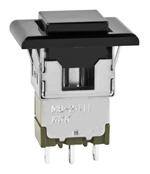
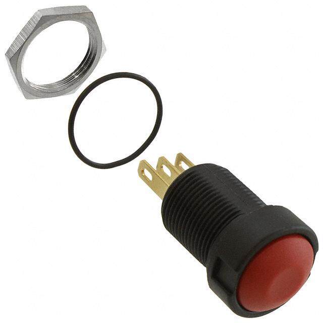
| 描述 | SWITCH PUSHBUTTON SPDT 3A 125V按钮开关 SP ON-(ON) SNP IN |
| 产品分类 | |
| 品牌 | NKK Switches |
| 产品手册 | |
| 产品图片 |
|
| rohs | 符合RoHS无铅 / 符合限制有害物质指令(RoHS)规范要求 |
| 产品系列 | 按钮开关,NKK Switches MB2411JW01-A-1AMB2400 |
| mouser_ship_limit | 该产品可能需要其他文件才能进口到中国。 |
| 数据手册 | |
| 产品型号 | MB2411JW01-A-1A |
| RoHS指令信息 | |
| 产品培训模块 | http://www.digikey.cn/PTM/IndividualPTM.page?site=cn&lang=zhs&ptm=7079http://www.digikey.cn/PTM/IndividualPTM.page?site=cn&lang=zhs&ptm=30248http://www.digikey.cn/PTM/IndividualPTM.page?site=cn&lang=zhs&ptm=30583 |
| 产品目录绘图 |
|
| 产品目录页面 | |
| 产品种类 | |
| 侵入防护 | - |
| 其它名称 | 360-2155 |
| 包装 | 散装 |
| 可燃性等级 | UL 94 V-0 |
| 商标 | NKK Switches |
| 外壳材料 | Diallyl Phthalate Resin |
| 安装类型 | 面板安装,卡入式 |
| 安装风格 | Panel |
| 工作温度 | -30°C ~ 85°C |
| 开关功能 | 开-瞬时 |
| 执行器 | Plunger, with Cap |
| 机械寿命 | 200,000 次循环 |
| 标准包装 | 1 |
| 照明 | None |
| 照明电压(标称值) | - |
| 照明类型,颜色 | - |
| 特性 | 环氧树脂密封端子 |
| 特色产品 | http://www.digikey.com/cn/zh/ph/NKK/MB2400.html |
| 电压额定值AC | 125 V |
| 电气寿命 | 25,000 次循环 |
| 电流额定值 | 3 A |
| 电路 | SPDT |
| 端子密封 | Epoxy |
| 端子类型 | 焊片 |
| 端接类型 | Solder Lug |
| 类型 | 标准 |
| 系列 | MB2400 |
| 致动器类型 | 方形,按钮 |
| 触点形式 | SPDT |
| 触点电镀 | Silver |
| 面板开口尺寸 | 矩形 - 15.00mm x 12.50mm |
| 颜色-致动器/盖帽 | 黑 |
| 额定电压-AC | 125V |
| 额定电压-DC | - |
| 额定电流 | 3A(AC) |


- 商务部:美国ITC正式对集成电路等产品启动337调查
- 曝三星4nm工艺存在良率问题 高通将骁龙8 Gen1或转产台积电
- 太阳诱电将投资9.5亿元在常州建新厂生产MLCC 预计2023年完工
- 英特尔发布欧洲新工厂建设计划 深化IDM 2.0 战略
- 台积电先进制程称霸业界 有大客户加持明年业绩稳了
- 达到5530亿美元!SIA预计今年全球半导体销售额将创下新高
- 英特尔拟将自动驾驶子公司Mobileye上市 估值或超500亿美元
- 三星加码芯片和SET,合并消费电子和移动部门,撤换高东真等 CEO
- 三星电子宣布重大人事变动 还合并消费电子和移动部门
- 海关总署:前11个月进口集成电路产品价值2.52万亿元 增长14.8%


.jpg)
PDF Datasheet 数据手册内容提取
Series MB2400 Snap-Action Pushbuttons s e ggl General Specifications o T s er Electrical Capacity (Resistive Load) k oc Power Level (silver): 3A @ 125V AC R Logic Level (gold): 0.4VA maximum @ 28V AC/DC maximum (Applicable Range 0.1mA ~ 0.1A @ 20mV ~ 28V) Logic/Power Level: Combines silver & gold ratings s n o (gold over silver) Note: Find additional explanation of dual rating & operating range in Supplement section. utt C b h s Pu Other Ratings B Contact Resistance: 20 milliohms maximum for silver; 30 milliohms maximum for gold P d Insulation Resistance: 1,000 megohms minimum @ 500V DC e nat Dielectric Strength: 1,000V AC minimum between contacts for 1 minute minimum; mi 1,500V AC minimum between contacts & case for 1 minute minimum u Ill Mechanical Life: 200,000 operations minimum e bl Electrical Life: 25,000 operations minimum for silver; 100,000 operations minimum for gold a m m Nominal Operating Force: Single pole 2.45N; double pole 3.92N a gr Travel Pretravel .024” (0.6mm); Overtravel .016” (0.4mm); Total Travel .039” (1.0mm) o Pr Materials & Finishes s k oc Plunger: Brass with nickel plating yl e Bushing: Brass with nickel plating K Frame: Stainless steel Case: Polybutylene terephthalate (PBT) (UL94V-0) es Base: Diallyl phthalate resin (UL94V-0) otari Movable Contactor: Phosphor bronze with silver or gold plating R Movable Contacts: Silver alloy (code W); copper with gold plating (code G); or silver alloy with gold plating (code A) Stationary Contacts: Silver alloy with silver plating (code W); copper or brass with gold plating (code G); or silver with gold plating (code A) s de Terminals: Copper or brass with silver plating; copper or brass with gold plating Sli Environmental Data s Operating Temp Range: –30°C through +85°C (–22°F through +185°F) e ctil Humidity: 90 ~ 95% humidity for 96 hours @ 40°C (104°F) Ta Vibration: 10 ~ 55Hz with peak-to-peak amplitude of 1.5mm traversing the frequency range & returning in 1 minute; 3 right angled directions for 2 hours Shock: 50G (490m/s2) acceleration (tested in 6 right angled directions, with 3 shocks in each direction) Tilt Installation Mounting Torque: 1.5Nm (13.0 lb•in) for double nut; 0.7Nm (6.0 lb•in) for single nut Cap Installation Force: 80.0N (18.0 lbf) maximum downward force on actuator h Soldering: Wave Soldering (PC version): See Profile B in Supplement section. c u o Manual Soldering: See Profile B in Supplement section. T Cleaning: These devices are not process sealed. Hand clean locally using alcohol based solution. See Cleaning Specifications in Supplement section. s or at dic Standards & Certifications n I Flammability Standards: UL94V-0 case & base UL: File No. E44145 - Recognized only when ordered with marking on switch. s e ori Add “/U” or “/CUL” before dash in part number to order UL recognized switch. ss All single and double pole models recognized at 3A @ 125V AC or 0.4VA max. @ 28V DC max. e cc CSA: File No. 023535_0_000 - Certified only when ordered with marking on switch. A Add “/C” before dash in part number to order CSA certified switch. nt Single pole models with PC, solder lug, or Wirewrap terminals & double pole with PC or e m e Wirewrap terminals certified at 3A @ 125V AC or 0.4VA @ 28V maximum. pl p u S C96 www.nkkswitches.com 3/13/17
Series MB2400 Snap-Action Pushbuttons s e Distinctive Characteristics ggl o T s er k Snap-acting mechanism gives smooth actuation, short stroke, oc R light touch, and audible feedback. This mechanism also provides long mechanical life. s n o C utt b h High torque bushing construction prevents rotation or separation s u P from frame during installation. B P d e at Antijamming design protects contacts from damage due to n mi excessive downward force on the actuator. Illu e bl a m Compatible companions with M series toggles. Body, m a bushing, and footprint dimensions ideal for mounting gr o MB2400 pushbuttons and M toggles next to one another. Pr s k c o Stainless steel frame resists corrosion. yl e K Longer center solder lug terminal simplifies wiring and s e soldering. ari ot R Silver contacts of specially composed alloy for hardness. s e d Epoxy sealed terminals prevent entry of solder flux and other Sli contaminants. s e Prominent external insulating barriers increase insulation resistance ctil a T and dielectric strength. Tilt Bushing Mount Page C98 ch u o Actual Size T s or at c di Bracket PC Mount Page C102 In s e ori s s e c c A Snap-in Mount Page C108 nt e m e pl p u S www.nkkswitches.com C97
Series MB2400 Snap-Action Snap-in Mount Pushbuttons s e gl TYPICAL SWITCH ORDERING EXAMPLE g o T ers MB24 11 J W 01 C k c o R s n o utt C b Poles & Circuits Contact Materials Cap & h s u & Ratings Cap Colors P 11 SPDT ON (ON) B Silver A Black ated P 61 ( D) =PD MTomeOnNtary (ON) W Rated 3A @ 125V AC B White min Gold C Red Illu G Rated 0.4VA max @ e 28V AC/DC max E Yellow bl ma Gold over Silver F Green m gra A Rated 3A @ 125V AC G Blue o & 0.4VA max @ 28V Pr H Gray AC/DC max s k c o yl e Mounting Frame Terminals K J Snap-in Frame 01 Solder Lug s 03 .250” (6.35mm) Straight PC e ari ot 05 .425” (10.8mm) Wirewrap R 06 .750” (19.05mm) Wirewrap 07 .964” (24.5mm) Wirewrap s e d Sli IMPORTANT: es Switches are supplied without UL, cULus & CSA marking unless specified. ctil UL, cULus & CSA recognized only when ordered with marking on the switch. a T Specific models, ratings, & ordering instructions are noted on the General Specifications page. Tilt DESCRIPTION FOR TYPICAL ORDERING EXAMPLE h MB2411JW01-C c u o T s Red Cap or at dic Snap-in Frame n SPDT I ON-(ON) Circuit s e ori Silver Contacts with s es 3-Amp Rating Solder Lug Terminals c c A nt e m e pl p u S C108 www.nkkswitches.com
Series MB2400 Snap-Action Snap-in Mount Pushbuttons s e TYPICAL SWITCH ORDERING EXAMPLE gl g o T 3 A C F ers k c o R s n o C utt Optional Bezels Bezel Colors LED Colors b h s u 1 Bezel without LEDs A Black 1 LED P B * 2 Bezel with 1 Round LED B White C Red P d e * 3 Bezel with 2 Round LEDs C Red F Green at n mi * 4 Bezel with 2 Rectangular LEDs E Yellow 2 LEDs u Ill * Available in Black color only F Green Top LED Bottom LED e bl a G Blue C Red C Red m m a H Gray E Yellow E Yellow gr o Pr F Green F Green s k c o yl e K s e ari ot R s e d Sli s e ctil a T Tilt DESCRIPTION FOR TYPICAL ORDERING EXAMPLE MB2411JW01-C-3A-CF h c u o T Red Cap 1 Red LED 1 Green LED Snap-in Frame Black Bezel s with 2 Round LEDs ator SPDT ON-(ON) Circuit c di Silver Contacts In with 3-Amp Rating s e ori Solder Lug Terminals s s e c c A nt e m e pl p u S www.nkkswitches.com C109
Series MB2400 Snap-Action Snap-in Mount Pushbuttons s e gl POLES & CIRCUITS g o T Plunger Position Connected Terminals Throw & Switch Schematics ( ) = Momentary ers Normal Down Normal Down ock Pole Model Note: Terminal numbers are not R actually on the switch. ns 1(COM) o utt C SP MB2411 ON (ON) 1-3 1-2 SPDT b 3 2 h s Pu 1 (COM) 4 DP MB2461 ON (ON) 1-3 4-6 1-2 4-5 DPDT B d P 3 2 6 5 e at min MOUNTING FRAME u Ill ble J Panel Cutout Panel Cutout ma Snap-in Frame for Single Pole for Double Pole m a without Bezel (15.0) without Bezel (15.0) gr .591 .591 o Pr (18.0) s .709 (12.5) (13.1) ck (2.85) Dia .492 .516 o .112 yl e Panel Thickness without Bezel: .039” ~ .157” (1.0mm ~ 4.0mm) K (12.2) Panel Thickness with Bezel: .039” ~ .126” (1.0mm ~ 3.2mm) .480 es CONTACT MATERIALS & RATINGS ari ot R W Silver over Silver Power Level 3A @ 125V AC s e d Sli G Gold over Brass or Copper Logic Level 0.4VA maximum @ 28V AC/DC maximum Note: Complete explanation of operating range in Supplement section. s e actil A Power Level 3A @ 125V AC T Gold over Silver or Logic Level or 0.4VA maximum @ 28V AC/DC maximum Note: This dual rated option is suitable when two or more identical switches are used in logic and in power circuits within the same application. See Supplement section for complete explanation of dual rating and operating range. Tilt TERMINALS .250” (6.35mm) 01 03 h (4.0) Touc Solder Lug Epoxy Seal .157 Straight PC Epoxy Seal (.418.89) (.62.5305) (2.0) (2.0) .079 (1.1) .079 (1.17) .043 .046 ors T h k = .(003.81) T h k = .(003.81) at c di Wirewrap or Extended PC n I (4.8) 05 .425” .189 es (10.8mm) 3 3 6 essori .750” Epoxy Seal A Refer to footprints if using 2(.418.75) Typ 2 5 (.418.75) Typ Acc 06 (19.05mm) as extended PC terminal. 1(1.8) Dia Typ 1 4 Dimension A = terminal .073 (1.8) Dia Typ ment 07 .964” Thk = (0.8) (.10.5207) lengths as shown beside .073 e (24.5mm) .031 the code boxes at left. Single Pole Double Pole pl p u S C110 www.nkkswitches.com
Series MB2400 Snap-Action Snap-in Mount Pushbuttons s e CAP & CAP COLORS gl g o T (3.8) AT465 (11.5) Sq .150 Contact factory .453” (11.5mm) .453 for matte finish. A B C E (8.4) Black White Red Yellow s Square Cap .331 er Legend details k c o Material: Polycarbonate at end of this F G H R Finish: Glossy section. Green Blue Gray s n o OPTIONAL SNAP-IN BEZELS & BEZEL COLORS C utt b h s u P 1 AT207 Bezel (.1416.85) A Black F Green (1.559.01) d PB e MFinaitsehr:i a lG: l oPsoslyycarbonate .(20.827) B White G Blue A Illuminat (12.0) C H Contact factory for matte (1.651.64) .472 Red Gray Single Pole Double Pole able (21.5) m finish. .846 E Yellow A (1.24.952)m”m (1.35.116)m”m gram o Pr 2 AT208 Bezel A cks for AT070 LED Black o B (8.8) Dia yl Material: Polycarbonate (19.0) (.1416.85) .(028.27) LED colors & specifications .346 Ke Finish: Glossy .748 (13.5) on next page. .531 Contact factory for Single Pole Double Pole (.1534.83) aries matte finish. (.1427.20) A (12.5)mm (13.1)mm (1.559.01) Rot (15.6) (30.2) .492” .516” .614 1.19 (6.25)mm (6.55)mm (5.4) Dia B .246” .258” A es .213 Slid AT212 Bezel 3 (12.0) A for AT617 LED (10.0) .472 Black .394 s e MPoalytecrairabl:o n ate (7.8) .(028.27) LoEnD n ceoxlto pras g&e .specifications (15.0) Tactil .307 .591 Finish: (11.8) Single Pole Double Pole Semi-glossy (8.0) .465(.2814.65) Sq .315 (.311.80) Dia Typ A (1.87.244)m”m (1.87.376)m”m A Tilt AT213 Bezel 4 (10.0) (12.0) A for AT618 LED .394 .472 Black h c u Material: (.20.709) Typ (2.2) LED colors & specifications To .087 Polycarbonate (7.8) on next page. (15.0) Finish: .307 .591 Semi-glossy (.1416.85) Single Pole Double Pole ors (.83.105) (5.0) Typ (.2814.65) Sq A (18.4)mm (18.7)mm A dicat .197 .724” .736” n I Bezel Assembly es ori s s 1. Pry out 2. Insert 3. Push tab 4. Snap ce tab on Tab 45° switch frame back into assembled Ac bezel to a under tab place. bezel and nt 45° angle. Tab and snap switch into me on the bezel. panel. ple p u S www.nkkswitches.com C111
Series MB2400 Snap-Action Snap-in Mount Pushbuttons s e gl LED COLORS & SPECIFICATIONS g o T Bezel Orientation on Switch s er AT070 LED AT617 LED AT618 LED k Roc Fwoitrh B 1e zLeElD AT208 (.52.0008) Dia Fwoitrh B 2e zReol uAnTd2 1LE2D s (.311.80) Dia Fwoitrh B 2e zReel cAtaTn2g1u3l ar LEDs (.519.07) ns .(370.73) (.519.07) .(27.706) o Pushbuttuminated PBC Circuit Mark This Side TBooptt oLEmD LED Circuit Mark This Side (+) (-) TBooptt oLEmD LED Circuit Mark This Side (+) (-) Ill (-) ble (+) a m m Note: Lead lengths may differ from manufacturing lot to lot. The longer lead is the anode (+). a gr o Pr AT070 AT617 AT618 s k yloc (+) (-) C F C E F C E F e K Color Red Green Red Yellow Green Red Yellow Green Maximum Forward Current I 25mA 50mA 30mA 30mA 25mA 25mA 30mA 25mA es FM Rotari Typical Forward Current IF 20mA 30mA 20mA 20mA 20mA 20mA 20mA 20mA Forward Voltage V 2.8V 2.1V 2.0V 2.1V 2.25V 2.25V 2.1V 2.2V F s Maximum Reverse Voltage V 4V 5V 5V 5V 5V 5V 5V 5V de RM Sli Current Reduction Rate 0.33 0.40 0.40 0.40 0.33 0.33 0.40 0.33 Above 25°C ∆I mA/°C mA/°C mA/°C mA/°C mA/°C mA/°C mA/°C mA/°C F Ambient Temperature Range es –10° ~ +70°C –15° ~ +70°C –25° ~ +70°C ctil (when used with a bezel) a T The electrical specifications shown are determined at a basic temperature of 25°C. LED circuit is independent of switch operation. LED is colored in OFF state. Tilt If the source voltage is greater than the rated voltage of the LED, a ballast resistor must be connected in series with the LED. The ballast resistor calculation and more lamp detail are shown in the Supplement section. TYPICAL SWITCH DIMENSIONS h c u o T Solder Lug Single Pole Double Pole s Circuit Mark (1.1) x (2.0) Typ or This Side .039 x .079 at (0.8) Typ dic .031 In NC 3 NC 6 3 s (.1780.09) (.1415.53) Sq (4.7) Typ ( 1.531.02) NO 2 (.1545.10) NO 5 2 (.1545.10) orie .185 COM 1 COM 4 1 s s e (4.0) (2.0) cc .157 .079 A (0.5) (4.5) (2.0) (4.8) .020 .177 .079 .189 ent (.1428.20) (.313.30) ( 2.948.90) (.73.191) (.1520.07) m e pl MB2411JW01-C p u S C112 www.nkkswitches.com
Series MB2400 Snap-Action Snap-in Mount Pushbuttons s e TYPICAL SWITCH DIMENSIONS gl g o T Single & Double Pole Solder Lug • AT207 Bezel CThiricsu Sit idMeark .(014.13) xx .(027.09) Typ kers (0.8) Typ oc .031 R NC 3 NC 6 3 (.2814.65) (.1415.53) Sq (4.7) Typ ( 1.531.02) NO 2 (.1545.10) NO 5 2 (.1545.10) ons .185 COM 1 COM 4 1 C utt b h s u (2.2) (4.0) (2.0) Typ P .087 .157 .079 B (4.5) (2.0) (4.8) P .177 .079 .189 d e (15.6) (4.0) (24.2) (7.9) (12.7) at .614 .157 .953 .311 .500 n MB2411JW01-C-1A mi u Ill e Single Pole Solder Lug • AT208 Bezel bl a m (4.9) (15.3) Min (2.5) m .193 .602 (0.61) Sq .098 gra (5.4) Dia .024 Pro .213 (19.0) ( 31.019.20) (.1533.15).748 CThiricsu Sitid Meark(4.7) Typ NC 3 (13.0) eylocks (12.0) .185 NO 2 .512 K .472 (14.0) (0.8) Typ COM 1 .551 .031 (1.1) x (2.0) Typ es .043 x .079 ari (4.0) ot (11.8) (2.2) .(145.57) (2.0) R .465 .087 .177 .079 (.1651.46) .(415.07) (2.945.32) (.73.191) MB2411JW01-C-2A-C s e d Sli Single Pole Solder Lug • AT212 Bezel (10.0) (7.8) Circuit Mark (1.1) x (2.0) Typ .394 .307 This Side .043 x .079 s e (.20.958) Typ ctil a NC 3 T (4.7) Typ (13.0) (8.0) (12.0) (11.5) Sq .185 NO 2 .512 .315 .472 .453 (14.0) (0.8) Typ COM 1 .551 (.311.80) Dia Typ .031 Tilt (2.2) (4.0) (0.5) Sq Typ .087 .157 .020 (11.8) (4.5) (2.0) .465 .177 .079 (21.5) Sq (4.0) (24.2) (7.8) (7.9) .846 .157 .953 .307 .311 MB2411JW01-C-3A-CF ch u o T Double Pole Solder Lug • AT213 Bezel s (.1309.40) .(370.87) CThiricsu Sitid Meark .(014.13) xx .(027.09) Typ ator c (2.5) Typ di .098 n I (4.7) Typ NC 6 3 (13.0) (.83.105) (.1427.20) (.1415.53) Sq (0.1.885) Typ CONMO 54 21 .512(.1545.10) ssories (5.0) Typ .031 ce .197 Ac (2.0) (2.2) (4.0) (0.5) Sq Typ (2.0) Typ .079 .087 .157 .020 .079 (.1416.85) (.417.57) (.418.89) ment (.2814.65) Sq (.415.07) ( 2.945.23) .(370.87) (.1520.07) MB2461JW01-C-4A-CF ple p u S www.nkkswitches.com C113
Series MB2400 Snap-Action Snap-in Mount Pushbuttons s e gl LEGENDS g o T NKK Switches can provide custom legends for caps. Contact factory for more information. s er k c Ro Suggested Printable Area for Cap s on (0.38) Typ (4.61) Typ butt C ON Recommended Print Method: .015 .181 h s Pu Screen Print or Pad Print (0.76) Typ B (9.98) Sq (0.76) Typ .030 (9.98) (0.76) Typ d P Epoxy based ink is recommended. .393 .030 .393 .030 e (11.5) Sq (11.5) Sq at .453 .453 Illumin FILTEARIR AT465 AT465 e bl a m Shaded areas are printable areas. m a gr o Pr s k c o yl e K s e ari ot R s e d Sli s e ctil a T Tilt h c u o T s or at c di n I s e ori s s e c c A nt e m e pl p u S C114 www.nkkswitches.com
Mouser Electronics Authorized Distributor Click to View Pricing, Inventory, Delivery & Lifecycle Information: N KK Switches: MB2411E1W03-RO MB2411JG01-A-2A MB2411T1W01 MB2461A2G15-FA-RO MB2461A2W15-FA-RO MB2461E1W01-RO MB2411S1W01-RO MB2461E1A01-HC-RO MB2411A1W03-HC-RO MB2411A2W30-HA-RO MB2411E1A01-FB-RO MB2411JG01/UC-A-2A