
 Datasheet下载
- 型号: MAL214699107E3
- 制造商: Vishay
- 库位|库存: xxxx|xxxx
- 要求:
| 数量阶梯 | 香港交货 | 国内含税 |
| +xxxx | $xxxx | ¥xxxx |
查看当月历史价格
查看今年历史价格
MAL214699107E3产品简介:
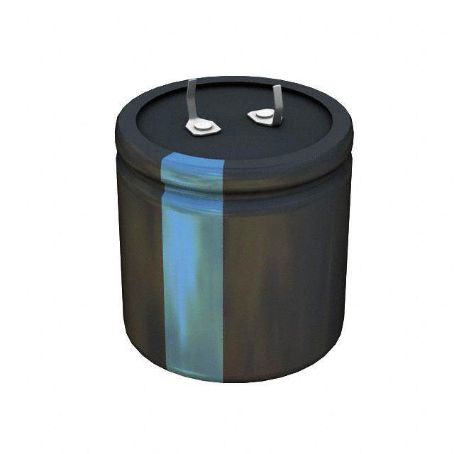
ICGOO电子元器件商城为您提供MAL214699107E3由Vishay设计生产,在icgoo商城现货销售,并且可以通过原厂、代理商等渠道进行代购。 MAL214699107E3价格参考。VishayMAL214699107E3封装/规格:铝电解电容器, 330µF 50V 铝电解电容器 径向,Can - SMD 125°C 时为 4000 小时。您可以下载MAL214699107E3参考资料、Datasheet数据手册功能说明书,资料中有MAL214699107E3 详细功能的应用电路图电压和使用方法及教程。
| 参数 | 数值 |
| 产品目录 | |
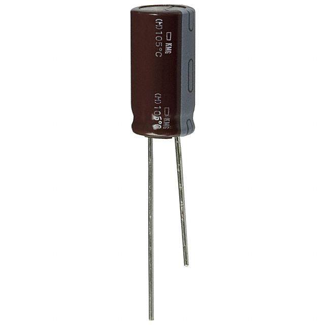
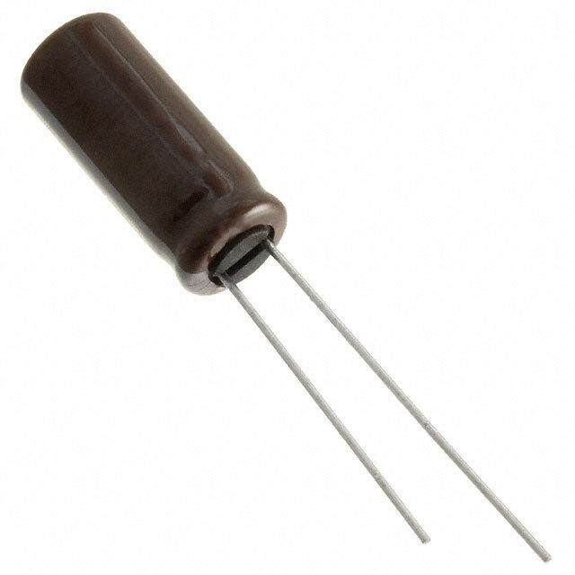
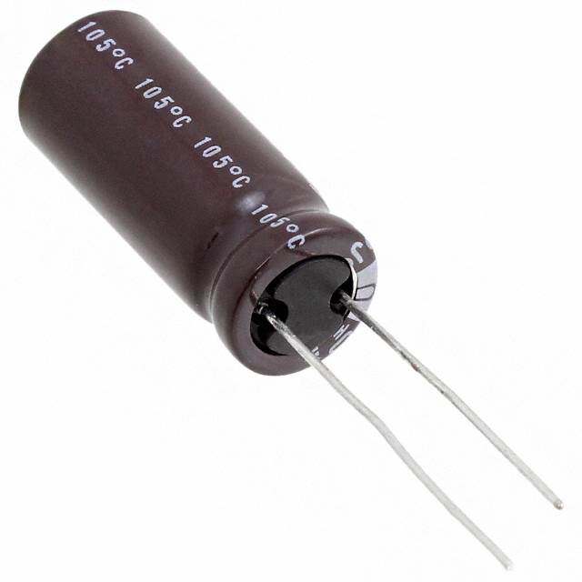
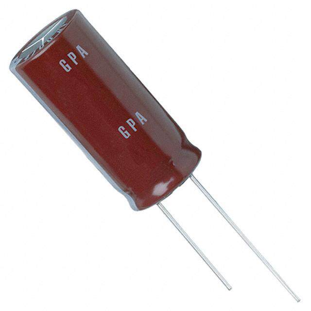
| 描述 | CAP ALUM 330UF 50V 20% SMD铝质电解电容器-SMD 330uF 50V 20% |
| ESR(等效串联电阻) | - |
| 产品分类 | |
| 品牌 | Vishay BC ComponentsVishay / BC Components |
| 产品手册 | |
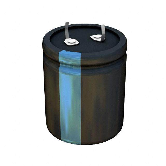
| 产品图片 |
|
| rohs | 符合RoHS无铅 / 符合限制有害物质指令(RoHS)规范要求 |
| 产品系列 | 铝电解电容器,铝质电解电容器-SMD,Vishay / BC Components MAL214699107E3146 CTI |
| 数据手册 | |
| 产品型号 | MAL214699107E3MAL214699107E3 |
| 不同温度时的使用寿命 | 125°C 时为 4000 小时 |
| 产品 | Aluminum Electrolytic Capacitors |
| 产品目录绘图 |
|
| 产品种类 | 铝质电解电容器-SMD |
| 其它名称 | 4441PHTR |
| 包装 | 带卷 (TR) |
| 商标 | Vishay / BC Components |
| 外壳宽度 | 12.5 mm |
| 外壳直径 | 12.5 mm |
| 外壳高度 | 16 mm |
| 大小/尺寸 | 0.492" 直径(12.50mm) |
| 安装类型 | 表面贴装 |
| 容差 | ±20%20 % |
| 封装 | Reel |
| 封装/外壳 | 径向,Can - SMD |
| 工作温度 | -55°C ~ 125°C |
| 应用 | 自动 |
| 引线间距 | - |
| 标准包装 | 200 |
| 电压额定值DC | 50 V |
| 电容 | 330µF330 uF |
| 端接类型 | SMD/SMT |
| 类型 | Aluminum Capacitors SMD (Chip) High Temperature, Low Impedance- |
| 系列 | 146 CTI |
| 纹波电流 | 1.1A |
| 表面贴装焊盘尺寸 | 0.492" 长 x 0.492" 宽(12.50mm x 12.50mm) |
| 阻抗 | 85 毫欧 |
| 额定电压 | 50V |
| 高度-安装(最大值) | 0.630"(16.00mm) |


- 商务部:美国ITC正式对集成电路等产品启动337调查
- 曝三星4nm工艺存在良率问题 高通将骁龙8 Gen1或转产台积电
- 太阳诱电将投资9.5亿元在常州建新厂生产MLCC 预计2023年完工
- 英特尔发布欧洲新工厂建设计划 深化IDM 2.0 战略
- 台积电先进制程称霸业界 有大客户加持明年业绩稳了
- 达到5530亿美元!SIA预计今年全球半导体销售额将创下新高
- 英特尔拟将自动驾驶子公司Mobileye上市 估值或超500亿美元
- 三星加码芯片和SET,合并消费电子和移动部门,撤换高东真等 CEO
- 三星电子宣布重大人事变动 还合并消费电子和移动部门
- 海关总署:前11个月进口集成电路产品价值2.52万亿元 增长14.8%
PDF Datasheet 数据手册内容提取
146 CTI www.vishay.com Vishay BCcomponents Aluminum Electrolytic Capacitors SMD (Chip), High Temperature, Low Impedance FEATURES • Extended useful life: up to 6000 h at 125 °C • Polarized aluminum electrolytic capacitors, non-solid electrolyte, self healing • SMD-version with base plate, lead (Pb)-free reflow solderable • Charge and discharge proof, no peak current limitation • Advanced temperature reflow soldering according to 140 CRH lower Z 146 CTI JEDEC® J-STD-020 125 °C higher I 125 °C R • Vibration proof, 4-pin version and 6-pin version lower Z • AEC-Q200 qualified 150 CRZ • High reliability 105 °C • Low ESR Fig. 1 • Material categorization: for definitions of compliance please see www.vishay.com/doc?99912 QUICK REFERENCE DATA APPLICATIONS DESCRIPTION VALUE • SMD technology, for high temperature reflow soldering Nominal case sizes 8 x 8 x 10 (L x W x H in mm) to 18 x 18 x 21 • Industrial and professional applications Rated capacitance range, CR 10 μF to 4700 μF • Automotive, general industrial, telecom Tolerance on CR ± 20 % • Smoothing, filtering, buffering Rated voltage range, U 16 V to 100 V R MARKING Category temperature range -55 °C to +125 °C • Rated capacitance (in μF) Endurance test at 125 °C 1000 h to 5000 h • Rated voltage (in V) Useful life at 125 °C 1500 h to 6000 h • Date code, in accordance with IEC 60062 Useful life at 40 °C 1.8 x l applied 150 000 h to 400 000 h • Black mark or “-” sign indicating the cathode (the anode is R identified by bevelled edges) Shelf life at 0 V, 125 °C 1000 h • Code indicating group number (T) Based on sectional IEC 60384-18 / CECC 32300 specification PACKAGING Climatic category IEC 60068 55 / 125 / 56 Supplied in blister tape on reel Revision: 05-Dec-16 1 Document Number: 28403 For technical questions, contact: aluminumcaps1@vishay.com THIS DOCUMENT IS SUBJECT TO CHANGE WITHOUT NOTICE. THE PRODUCTS DESCRIBED HEREIN AND THIS DOCUMENT ARE SUBJECT TO SPECIFIC DISCLAIMERS, SET FORTH AT www.vishay.com/doc?91000
146 CTI www.vishay.com Vishay BCcomponents SELECTION CHART FOR C , U , AND RELEVANT NOMINAL CASE SIZES (L x W x H in mm) R R CR UR (V) (μF) 16 25 35 50 63 80 100 10 10 x 10 x 10 10 x 10 x 10 22 10 x 10 x 10 10 x 10 x 10 10 x 10 x 10 33 8 x 8 x 10 10 x 10 x 10 10 x 10 x 10 10 x 10 x 12 47 10 x 10 x 10 10 x 10 x 10 10 x 10 x 10 10 x 10 x 12 10 x 10 x 12 68 10 x 10 x 10 10 x 10 x 10 10 x 10 x 12 12.5 x 12.5 x 13 10 x 10 x 10 10 x 10 x 12 100 8 x 8 x 10 10 x 10 x 10 12.5 x 12.5 x 13 12.5 x 12.5 x 16 10 x 10 x 12 12.5 x 12.5 x 13 150 10 x 10 x 10 10 x 10 x 12 12.5 x 12.5 x 13 12.5 x 12.5 x 16 16 x 16 x 16 16 x 16 x 21 220 8 x 8 x 10 10 x 10 x 10 10 x 10 x 12 12.5 x 12.5 x 13 12.5 x 12.5 x 16 16 x 16 x 16 18 x 18 x 16 16 x 16 x 21 330 10 x 10 x 10 10 x 10 x 12 12.5 x 12.5 x 13 12.5 x 12.5 x 16 16 x 16 x 16 18 x 18 x 21 18 x 18 x 16 470 10 x 10 x 12 12.5 x 12.5 x 13 12.5 x 12.5 x 16 16 x 16 x 16 16 x 16 x 16 18 x 18 x 21 - 680 12.5 x 12.5 x 13 12.5 x 12.5 x 16 16 x 16 x 16 16 x 16 x 16 18 x 18 x 16 - - 820 16 x 16 x 21 - - 16 x 16 x 21 - - 1000 12.5 x 12.5 x 16 16 x 16 x 16 16 x 16 x 16 18 x 18 x 21 18 x 18 x 16 - - 1200 18 x 18 x 16 18 x 18 x 21 - - - 1500 16 x 16 x 16 16 x 16 x 16 16 x 16 x 21 - - - - 1800 18 x 18 x 21 - - - - 16 x 16 x 21 - - - - - 2200 16 x 16 x 16 18 x 18 x 16 - - - - - 2700 18 x 18 x 21 - - - - - 16 x 16 x 21 - - - - - - 3300 18 x 18 x 16 - - - - - - 3900 18 x 18 x 21 - - - - - - 4700 18 x 18 x 21 - - - - - - 2-pin: 4-pin: 6-pin: ≤ Ø 10 mm Ø 12.5 mm ≥ Ø 16 mm x) H x) H x. 1.0 (2 MAX.M 0A.X3. x. 1.0 (2 MAXM. 0AX.3. 1.0 (2 x) MAHXM. A0X..3 ma ma x. A4-H220 u25V min. 0.4/ D L4-H2200u25V min. 0.4/ D R3-H1000u35V n. 0.4/ma D mi W W W MAX. MAX. MAX. B B B L1MAX. S LMAX. L1MAX. S LMAX. L1MAX. S LMAX. Fig. 2 - Dimensional outline Revision: 05-Dec-16 2 Document Number: 28403 For technical questions, contact: aluminumcaps1@vishay.com THIS DOCUMENT IS SUBJECT TO CHANGE WITHOUT NOTICE. THE PRODUCTS DESCRIBED HEREIN AND THIS DOCUMENT ARE SUBJECT TO SPECIFIC DISCLAIMERS, SET FORTH AT www.vishay.com/doc?91000
146 CTI www.vishay.com Vishay BCcomponents Table 1 DIMENSIONS in millimeters AND MASS NOMINAL CASE MASS CASE SIZE L W H Ø D B S L1 CODE MAX. MAX. MAX. MAX. MAX. (g) L x W x H 8 x 8 x 10 0810 8.5 8.5 10.5 8.0 1.0 2.2 10.2 1.0 10 x 10 x 10 1010 10.5 10.5 10.5 10.0 1.0 3.5 12.1 1.3 10 x 10 x 12 1012 10.5 10.5 12.5 10.0 1.0 3.5 12.1 1.5 12.5 x 12.5 x 13 1213 12.9 12.9 14.0 12.5 1.3 3.6 14.9 2.6 12.5 x 12.5 x 16 1216 12.9 12.9 16.5 12.5 1.3 3.6 14.9 2.8 16 x 16 x 16 1616 16.6 16.6 17.5 16.0 1.3 6.5 18.6 5.5 16 x 16 x 21 1621 16.6 16.6 22.0 16.0 1.3 6.5 18.6 6.0 18 x 18 x 16 1816 19.0 19.0 17.5 18.0 1.3 6.5 21.0 8.0 18 x 18 x 21 1821 19.0 19.0 22.0 18.0 1.3 6.5 21.0 8.3 Table 2 TAPE AND REEL DIMENSIONS in millimeters, PACKAGING QUANTITIES NOMINAL TAPE PACKAGING CASE PITCH TAPE WIDTH CASE SIZE THICKNESS REEL DIAMETER QUANTITY CODE P W L x W x H 1 T PER REEL 2 8 x 8 x 10 0810 16 24 11.6 380 500 10 x 10 x 10 1010 16 24 11.6 380 500 10 x 10 x 12 1012 16 24 12.8 330 250 12.5 x 12.5 x 13 1213 20 24 16.2 380 250 12.5 x 12.5 x 16 1216 24 32 18.5 380 200 16 x 16 x 16 1616 28 44 18.9 380 150 16 x 16 x 21 1621 28 44 23.4 380 100 18 x 18 x 16 1816 32 44 18.9 380 125 18 x 18 x 21 1821 32 44 23.4 380 100 Note • Detailed tape dimensions see section “PACKAGING” Revision: 05-Dec-16 3 Document Number: 28403 For technical questions, contact: aluminumcaps1@vishay.com THIS DOCUMENT IS SUBJECT TO CHANGE WITHOUT NOTICE. THE PRODUCTS DESCRIBED HEREIN AND THIS DOCUMENT ARE SUBJECT TO SPECIFIC DISCLAIMERS, SET FORTH AT www.vishay.com/doc?91000
146 CTI www.vishay.com Vishay BCcomponents MOUNTING SOLDERING The capacitors are designed for automatic placement on to Soldering conditions are defined by the curve, temperature printed-circuit boards. versus time, where the temperature is that measured on the component during processing. Optimum dimensions of soldering pads depend amongst others on soldering method, mounting accuracy, print For maximum conditions refer to Fig. 4. layout and / or adjacent components. Any temperature versus time curve which does not exceed For recommended soldering pad dimensions, refer to Fig. 3 the specified maximum curves may be applied. and Table 3. As a general principle, temperature and duration shall be the minimum necessary required to ensure good soldering connections. However, the specified maximum curves should never be exceeded. e a c a d b b f b d a c a a c a Case size Ø D ≤ 10 mm Case size Ø D = 12.5 mm Case size Ø D ≥ 16 mm Fig. 3 - Recommended soldering pad dimensions Table 3 RECOMMENDED SOLDERING PAD DIMENSIONS in millimeters CASE CODE a b c d e f 0810 4.4 2.5 3.0 - - - 1010 4.4 2.5 4.0 - - - 1012 4.4 2.5 4.0 - - - 1213 6.3 2.5 4.0 4.2 5.0 5.6 1216 6.3 2.5 4.0 4.2 5.0 5.6 1616 7.8 9.6 4.7 - - - 1621 7.8 9.6 4.7 - - - 1816 8.8 9.6 4.7 - - - 1821 8.8 9.6 4.7 - - - Revision: 05-Dec-16 4 Document Number: 28403 For technical questions, contact: aluminumcaps1@vishay.com THIS DOCUMENT IS SUBJECT TO CHANGE WITHOUT NOTICE. THE PRODUCTS DESCRIBED HEREIN AND THIS DOCUMENT ARE SUBJECT TO SPECIFIC DISCLAIMERS, SET FORTH AT www.vishay.com/doc?91000
146 CTI www.vishay.com Vishay BCcomponents ADVANCED SOLDERING PROFILE FOR LEAD (Pb)-FREE REFLOW PROCESS ACCORDING TO JEDEC J-STD-020 T (°C) T Peak 230 t 217 4 t 200 3 190 t 2 150 t 1 25 time (s) Fig. 4 - Maximum temperature load during reflow soldering Table 4 REFLOW SOLDERING CONDITIONS for MAL214699xxxE3 CASE CODE CASE CODE CASE CODE PROFILE FEATURES 0810 TO 1012 1213 TO 1216 1616 TO 1821 Max. time from 25 °C to T 300 s 300 s 300 s Peak Max. ramp-up rate to 150 °C 3 K/s 3 K/s 3 K/s Max. time from 150 °C to 200 °C (t ) 150 s 150 s 150 s 1 Max. time from 190 °C to 200 °C (t ) 110 s 110 s 110 s 2 Ramp up rate from 200 °C to T 0.5 K/s to 3 K/s 0.5 K/s to 3 K/s 0.5 K/s to 3 K/s Peak Max. time above T (217 °C) (t ) 90 s 90 s 90 s Liquidus 3 Max. time above 230 °C (t ) 70 s 65 s 60 s 4 Peak temperature T 260 °C 250 °C 245 °C Peak Max. time above T minus 5 °C 40 s 30 s 30 s Peak Ramp-down rate from T 3 K/s to 6 K/s 3 K/s to 6 K/s 3 K/s to 6 K/s Liquidus Notes • Temperature measuring point on top of the case and on terminals. • Max. 2 runs with pause of min. 30 min in between. Revision: 05-Dec-16 5 Document Number: 28403 For technical questions, contact: aluminumcaps1@vishay.com THIS DOCUMENT IS SUBJECT TO CHANGE WITHOUT NOTICE. THE PRODUCTS DESCRIBED HEREIN AND THIS DOCUMENT ARE SUBJECT TO SPECIFIC DISCLAIMERS, SET FORTH AT www.vishay.com/doc?91000
146 CTI www.vishay.com Vishay BCcomponents ORDERING EXAMPLE ELECTRICAL DATA Electrolytic capacitor 146 CTI series SYMBOL DESCRIPTION C Rated capacitance at 100 Hz, tolerance ± 20 % 220 μF / 50 V; ± 20 % R IR Rated RMS ripple current at 100 kHz, 125 °C Nominal case size: 12.5 mm x 12.5 mm x 13 mm; taped on IL2 Max. leakage current after 2 min at UR reel tan Max. dissipation factor at 100 Hz Ordering code: MAL214699106E3 Z Max. impedance at 100 kHz Note • Unless otherwise specified, all electrical values in Table 5 apply at T = 20 °C, P = 86 kPa to 106 kPa, RH = 45 % to 75 % amb Table 5 ELECTRICAL DATA AND ORDERING INFORMATION NOMINAL I Z Z R I UR CR CASE SIZE 125 °C 2 mL2in tan 100 kHz 100 kHz LIFE ORDERING CODE (V) (μF) L x W x H 100 kHz 100 Hz 20 °C -40 °C CODE (1) MAL2146... (μA) (mm) (mA) () () 220 8 x 8 x 10 650 35 0.16 0.300 2.40 L1 99512E3 330 10 x 10 x 10 750 53 0.16 0.150 1.35 L1 99501E3 470 10 x 10 x 12 900 75 0.16 0.097 0.87 L2 99502E3 680 12.5 x 12.5 x 13 1100 109 0.16 0.075 0.68 L4 99503E3 1000 12.5 x 12.5 x 16 1300 160 0.16 0.058 0.52 L5 99504E3 16 1500 16 x 16 x 16 1400 240 0.16 0.050 0.45 L6 99505E3 2200 16 x 16 x 16 1400 352 0.18 0.050 0.45 L6 99506E3 3300 16 x 16 x 21 1660 528 0.20 0.035 0.32 L7 99507E3 3300 18 x 18 x 16 1500 528 0.20 0.050 0.45 L6 99508E3 3900 18 x 18 x 21 1750 624 0.20 0.035 0.32 L7 99509E3 4700 18 x 18 x 21 1750 752 0.22 0.035 0.32 L7 99511E3 100 8 x 8 x 10 650 25 0.14 0.300 2.40 L1 99611E3 220 10 x 10 x 10 750 55 0.14 0.150 1.35 L1 99601E3 330 10 x 10 x 12 900 83 0.14 0.097 0.87 L2 99602E3 470 12.5 x 12.5 x 13 1100 118 0.14 0.075 0.68 L4 99603E3 680 12.5 x 12.5 x 16 1300 170 0.14 0.058 0.52 L5 99604E3 25 1000 16 x 16 x 16 1400 250 0.14 0.050 0.45 L6 99605E3 1500 16 x 16 x 16 1400 375 0.14 0.050 0.45 L6 99606E3 2200 16 x 16 x 21 1660 550 0.16 0.035 0.32 L7 99607E3 2200 18 x 18 x 16 1500 550 0.16 0.050 0.45 L6 99608E3 2700 18 x 18 x 21 1750 675 0.16 0.035 0.32 L7 99609E3 33 8 x 8 x 10 650 12 0.12 0.300 2.40 L1 99013E3 47 10 x 10 x 10 750 17 0.12 0.150 1.35 L1 99001E3 100 10 x 10 x 10 750 35 0.12 0.150 1.35 L1 99002E3 150 10 x 10 x 10 750 53 0.12 0.150 1.35 L1 99003E3 220 10 x 10 x 12 900 77 0.12 0.097 0.87 L2 99004E3 330 12.5 x 12.5 x 13 1100 116 0.12 0.075 0.68 L4 99005E3 35 470 12.5 x 12.5 x 16 1300 165 0.12 0.058 0.52 L5 99006E3 680 16 x 16 x 16 1400 238 0.12 0.050 0.45 L6 99007E3 1000 16 x 16 x 16 1400 350 0.12 0.050 0.45 L6 99008E3 1200 18 x 18 x 16 1500 420 0.12 0.050 0.45 L6 99009E3 1500 16 x 16 x 21 1660 525 0.12 0.035 0.32 L7 99011E3 1800 18 x 18 x 21 1750 630 0.12 0.035 0.32 L7 99012E3 47 10 x 10 x 10 600 24 0.10 0.240 2.16 L1 99101E3 68 10 x 10 x 10 600 34 0.10 0.240 2.16 L1 99102E3 100 10 x 10 x 10 600 50 0.10 0.240 2.16 L1 99103E3 100 10 x 10 x 12 700 50 0.10 0.170 1.53 L2 99104E3 150 10 x 10 x 12 700 75 0.10 0.170 1.53 L2 99105E3 220 12.5 x 12.5 x 13 900 110 0.10 0.120 1.08 L4 99106E3 50 330 12.5 x 12.5 x 16 1100 165 0.10 0.085 0.76 L5 99107E3 470 16 x 16 x 16 1300 235 0.10 0.072 0.65 L6 99108E3 680 16 x 16 x 16 1300 340 0.10 0.072 0.65 L6 99109E3 1000 16 x 16 x 21 1500 500 0.10 0.052 0.47 L7 99111E3 1000 18 x 18 x 16 1300 500 0.10 0.070 0.63 L6 99112E3 1200 18 x 18 x 21 1600 600 0.10 0.049 0.44 L7 99113E3 Revision: 05-Dec-16 6 Document Number: 28403 For technical questions, contact: aluminumcaps1@vishay.com THIS DOCUMENT IS SUBJECT TO CHANGE WITHOUT NOTICE. THE PRODUCTS DESCRIBED HEREIN AND THIS DOCUMENT ARE SUBJECT TO SPECIFIC DISCLAIMERS, SET FORTH AT www.vishay.com/doc?91000
146 CTI www.vishay.com Vishay BCcomponents ELECTRICAL DATA AND ORDERING INFORMATION NOMINAL I Z Z R I UR CR CASE SIZE 125 °C 2 mL2in tan 100 kHz 100 kHz LIFE ORDERING CODE (V) (μF) L x W x H 100 kHz 100 Hz 20 °C -40 °C CODE (1) MAL2146... (μA) (mm) (mA) () () 22 10 x 10 x 10 400 14 0.10 0.430 3.90 L1 99801E3 33 10 x 10 x 10 470 21 0.10 0.380 3.40 L1 99802E3 47 10 x 10 x 10 470 30 0.10 0.380 3.40 L1 99803E3 68 10 x 10 x 10 470 43 0.10 0.380 3.40 L1 99804E3 100 10 x 10 x 12 550 63 0.10 0.290 2.61 L2 99805E3 100 12.5 x 12.5 x 13 650 63 0.10 0.210 1.89 L4 99806E3 63 150 12.5 x 12.5 x 13 650 95 0.10 0.210 1.89 L4 99807E3 220 12.5 x 12.5 x 16 800 139 0.10 0.160 1.44 L5 99808E3 330 16 x 16 x 16 1050 208 0.10 0.100 0.90 L6 99809E3 470 16 x 16 x 16 1050 296 0.10 0.100 0.90 L6 99811E3 680 18 x 18 x 16 1150 428 0.10 0.095 0.86 L6 99812E3 820 16 x 16 x 21 1300 517 0.10 0.075 0.68 L7 99813E3 1000 18 x 18 x 21 1400 630 0.10 0.072 0.65 L7 99814E3 10 10 x 10 x 10 240 8 0.12 0.800 6.40 L2 99701E3 22 10 x 10 x 10 240 18 0.12 0.800 6.40 L2 99702E3 33 10 x 10 x 10 240 26 0.12 0.800 6.40 L2 99703E3 47 10 x 10 x 12 270 38 0.12 0.620 4.96 L2 99704E3 68 10 x 10 x 12 270 54 0.12 0.620 4.96 L2 99705E3 80 100 12.5 x 12.5 x 13 580 80 0.12 0.350 2.80 L3 99706E3 150 12.5 x 12.5 x 16 630 120 0.12 0.250 2.00 L3 99707E3 220 16 x 16 x 16 900 176 0.12 0.180 1.44 L3 99708E3 330 16 x 16 x 21 1100 264 0.12 0.120 0.96 L3 99709E3 330 18 x 18 x 16 900 264 0.12 0.160 1.28 L3 99711E3 470 18 x 18 x 21 1100 376 0.12 0.110 0.88 L3 99712E3 10 10 x 10 x 10 200 10 0.12 1.200 9.50 L2 99901E3 22 10 x 10 x 10 200 22 0.12 1.200 9.50 L2 99902E3 33 10 x 10 x 12 230 33 0.12 0.930 7.40 L2 99903E3 47 10 x 10 x 12 230 47 0.12 0.930 7.40 L2 99904E3 68 12.5 x 12.5 x 13 390 68 0.12 0.650 5.20 L3 99905E3 100 100 12.5 x 12.5 x 16 420 100 0.12 0.500 4.00 L3 99906E3 150 16 x 16 x 16 650 150 0.12 0.300 2.40 L3 99907E3 220 16 x 16 x 21 810 220 0.12 0.230 1.80 L3 99908E3 220 18 x 18 x 16 650 220 0.12 0.300 2.40 L3 99909E3 330 18 x 18 x 21 810 330 0.12 0.230 1.80 L3 99911E3 Note • Determines the applicable row in the table “Endurance Test Duration and Useful Life” Table 6 ADDITIONAL ELECTRICAL DATA PARAMETER CONDITIONS VALUE Voltage Surge voltage for short periods IEC 60384-18, subclause 4.14 Us 1.15 x UR Reverse voltage for short periods IEC 60384-18, subclause 4.16; TA 105 °C Urev 1 V Current Leakage current After 2 min at UR IL2 0.01 x CR x UR Inductance Ø D = 8 mm Typ. 6 nH Equivalent series inductance (ESL) Ø D = 10 mm Typ. 8 nH Ø D 12.5 mm Typ. 11 nH Resistance Equivalent series resistance (ESR) at 100 Hz Calculated from tan max. and CR (see Table 5) ESR = tan /2fCR Revision: 05-Dec-16 7 Document Number: 28403 For technical questions, contact: aluminumcaps1@vishay.com THIS DOCUMENT IS SUBJECT TO CHANGE WITHOUT NOTICE. THE PRODUCTS DESCRIBED HEREIN AND THIS DOCUMENT ARE SUBJECT TO SPECIFIC DISCLAIMERS, SET FORTH AT www.vishay.com/doc?91000
146 CTI www.vishay.com Vishay BCcomponents CAPACITANCE (C) DISSIPATION FACTOR (tan ) 1.2 10 C C tan 0 1.1 1 tan0 2 1.0 1 2 0.9 1 Curve 1: 16 V Curve 2: 63 V 0.8 0.1 -60 -40 -20 0 20 40 60 80 100 120 -60 -40 -20 0 20 40 60 80 100 120 140 C0 = Capacitance at 20 °C, 100 Hz Tamb (°C) tan δ0 = Typical tan δ at 20 °C, 100 Hz Tamb (°C) Fig. 5 - Typical multiplier of capacitance as a function Fig. 6 - Typical multiplier of dissipation factor (tan ) of ambient temperature as a function of ambient temperature EQUIVALENT SERIES RESISTANCE (ESR) IMPEDANCE (Z) 10 100 Curve 1: 220-25-1010 Z Curve 2: 330-25-1012 ESR (Ω) Curve 3: 470-25-1213 ESR0 10 Curve 4: 680-25-1216 Curve 5: 1500-25-1616 Curve 6: 2700-25-1821 1 1 1 2 3 4 0.1 5 6 0.1 0.01 10 102 103 104 f (Hz) 105 10 100 1000 10 000 100 000 ESR = typical ESR at 20 °C, 100 Hz T = 20 °C f (Hz) 0 amb Fig. 7 - Typical multiplier of ESR as a function of frequency Fig. 8 - Typical impedance as a function of frequency IMPEDANCE (Z) 1000 10 000 Z Curve 1: 68-63-1010 Z Curve 1: 10-100-1010 (Ω) Curve 2: 100-63-1012 (Ω) Curve 2: 47-100-1012 Curve 3: 150-63-1213 100 Curve 4: 220-63-1216 1000 Curve 3: 68-100-1213 Curve 5: 470-63-1616 Curve 4 : 100-100-1216 Curve 6: 1000-63-1821 Curve 5 : 150-100-1616 1 10 100 Curve 6 : 220-100-1621 Curve 7 : 330-100-1821 1 2 2 1 34 10 34 5 5 6 6 7 0.1 1 0.01 0.1 10 100 1000 10 000 100 000 10 100 1000 10 000 100 000 f (Hz) f (Hz) Fig. 9 - Typical impedance as a function of frequency Fig. 10 - Typical impedance as a function of frequency Revision: 05-Dec-16 8 Document Number: 28403 For technical questions, contact: aluminumcaps1@vishay.com THIS DOCUMENT IS SUBJECT TO CHANGE WITHOUT NOTICE. THE PRODUCTS DESCRIBED HEREIN AND THIS DOCUMENT ARE SUBJECT TO SPECIFIC DISCLAIMERS, SET FORTH AT www.vishay.com/doc?91000
146 CTI www.vishay.com Vishay BCcomponents RIPPLE CURRENT AND USEFUL LIFE Table 7 ENDURANCE TEST DURATION AND USEFUL LIFE ENDURANCE AT 125 °C USEFUL LIFE AT 125 °C USEFUL LIFE AT 40 °C LIFE CODE (h) (h) 1.8 x I APPLIED (h) R L1 1000 1500 150 000 L2 1500 2000 200 000 L3 2000 2500 250 000 L4 2500 3000 300 000 L5 3000 4000 325 000 L6 4000 5000 350 000 L7 5000 6000 400 000 Note • Multiplier of useful life code: MBC242 MBC242 I 4.3 A I R 4.2 4.1 4.0 3.9 3.8 3.7 3.6 3.5 3.4 3.3 3.2 3.1 3.0 Lifetime multiplier 2.8 1.0 2.6 1.5 2.0 2.4 3.0 2.2 4.0 I = Actual ripple current at 100 kHz 2.0 8.06.0 A 12 I = Rated ripple current at 100 kHz, 125 °C 1.8 (1R) Useful life at 125 °C and IR applied; 1.6 3020 see Table 7 1.4 60 1.2 100 10..08 200 (1) 0.5 400 0.0 40 50 60 70 80 90 100 110 120 130 T (°C) amb Fig. 11 - Multiplier of useful life as a function of ambient temperature and ripple current load Revision: 05-Dec-16 9 Document Number: 28403 For technical questions, contact: aluminumcaps1@vishay.com THIS DOCUMENT IS SUBJECT TO CHANGE WITHOUT NOTICE. THE PRODUCTS DESCRIBED HEREIN AND THIS DOCUMENT ARE SUBJECT TO SPECIFIC DISCLAIMERS, SET FORTH AT www.vishay.com/doc?91000
146 CTI www.vishay.com Vishay BCcomponents Table 8 MULTIPLIER OF RIPPLE CURRENT (I ) AS A FUNCTION OF FREQUENCY R FREQUENCY (Hz) U R (V) 50 100 300 1000 3000 10 000 30 000 100 000 16 0.60 0.70 0.80 0.85 0.90 0.95 0.97 1.00 25 0.60 0.70 0.80 0.85 0.90 0.95 0.97 1.00 35 0.45 0.65 0.80 0.85 0.90 0.95 0.97 1.00 50 0.40 0.60 0.75 0.82 0.90 0.95 0.97 1.00 63 0.40 0.60 0.75 0.82 0.90 0.95 0.97 1.00 80 0.40 0.60 0.75 0.82 0.90 0.95 0.97 1.00 100 0.40 0.60 0.75 0.82 0.90 0.95 0.97 1.00 Table 9 TEST PROCEDURES AND REQUIREMENTS TEST PROCEDURE REQUIREMENTS (quick reference) NAME OF TEST REFERENCE Shall be performed prior to tests mentioned below; C/C: ± 5 % IEC 60384-18, reflow soldering; Mounting tan spec. limit subclause 4.3 for maximum temperature load refer to chapter “Mounting” IL2 spec. limit Endurance ICEECC 6C0 338243-0108, / Tamb = 125 °C; UR applied; UtaRn 16 2 V x; spCe/cC.: l±im 2it0 % for test duration see Table 7 subclause 4.15 IL2 spec. limit C/C: ± 30 % tan 3 x spec. limit Useful life CsuEbCcCla u3s0e3 011.8,.1 Tfoarm tbe s=t 1d2u5r a°tCio;n U sRe aen Tda IbRl ea p7plied; IL2 spec. limit no short or open circuit total failure percentage: 1 % Shelf life IEC 60384-18 / Tamb = 125 °C; no voltage applied; 1000 h For requirements (storage at high CECC 32300, temperature) subclause 4.17 after test: UR to be applied for 30 min, see “Endurance test” above 24 h to 48 h before measurement IEC 60384-18 / Tamb = 125 °C: C/C: ± 15 % Reverse voltage CECC 32300, 125 h at U = -0.5 V, tan 1.5 x spec. limit subclause 4.16 followed by 125 h at UR IL2 spec. limit Statements about product lifetime are based on calculations and internal testing. They should only be interpreted as estimations. Also due to external factors, the lifetime in the field application may deviate from the calculated lifetime. In general, nothing stated herein shall be construed as a guarantee of durability. Revision: 05-Dec-16 10 Document Number: 28403 For technical questions, contact: aluminumcaps1@vishay.com THIS DOCUMENT IS SUBJECT TO CHANGE WITHOUT NOTICE. THE PRODUCTS DESCRIBED HEREIN AND THIS DOCUMENT ARE SUBJECT TO SPECIFIC DISCLAIMERS, SET FORTH AT www.vishay.com/doc?91000
Legal Disclaimer Notice www.vishay.com Vishay Disclaimer ALL PRODUCT, PRODUCT SPECIFICATIONS AND DATA ARE SUBJECT TO CHANGE WITHOUT NOTICE TO IMPROVE RELIABILITY, FUNCTION OR DESIGN OR OTHERWISE. Vishay Intertechnology, Inc., its affiliates, agents, and employees, and all persons acting on its or their behalf (collectively, “Vishay”), disclaim any and all liability for any errors, inaccuracies or incompleteness contained in any datasheet or in any other disclosure relating to any product. Vishay makes no warranty, representation or guarantee regarding the suitability of the products for any particular purpose or the continuing production of any product. To the maximum extent permitted by applicable law, Vishay disclaims (i) any and all liability arising out of the application or use of any product, (ii) any and all liability, including without limitation special, consequential or incidental damages, and (iii) any and all implied warranties, including warranties of fitness for particular purpose, non-infringement and merchantability. Statements regarding the suitability of products for certain types of applications are based on Vishay’s knowledge of typical requirements that are often placed on Vishay products in generic applications. Such statements are not binding statements about the suitability of products for a particular application. It is the customer’s responsibility to validate that a particular product with the properties described in the product specification is suitable for use in a particular application. Parameters provided in datasheets and / or specifications may vary in different applications and performance may vary over time. All operating parameters, including typical parameters, must be validated for each customer application by the customer’s technical experts. Product specifications do not expand or otherwise modify Vishay’s terms and conditions of purchase, including but not limited to the warranty expressed therein. Except as expressly indicated in writing, Vishay products are not designed for use in medical, life-saving, or life-sustaining applications or for any other application in which the failure of the Vishay product could result in personal injury or death. Customers using or selling Vishay products not expressly indicated for use in such applications do so at their own risk. Please contact authorized Vishay personnel to obtain written terms and conditions regarding products designed for such applications. No license, express or implied, by estoppel or otherwise, to any intellectual property rights is granted by this document or by any conduct of Vishay. Product names and markings noted herein may be trademarks of their respective owners. © 2017 VISHAY INTERTECHNOLOGY, INC. ALL RIGHTS RESERVED Revision: 08-Feb-17 1 Document Number: 91000
Mouser Electronics Authorized Distributor Click to View Pricing, Inventory, Delivery & Lifecycle Information: V ishay: MAL214699106E3 MAL214699107E3 MAL214699108E3 MAL214699109E3 MAL214699111E3 MAL214699112E3 MAL214699113E3 MAL214699801E3 MAL214699802E3 MAL214699803E3 MAL214699804E3 MAL214699805E3 MAL214699806E3 MAL214699807E3 MAL214699808E3 MAL214699809E3 MAL214699811E3 MAL214699812E3 MAL214699813E3 MAL214699814E3 MAL214699501E3 MAL214699502E3 MAL214699503E3 MAL214699504E3 MAL214699505E3 MAL214699506E3 MAL214699507E3 MAL214699508E3 MAL214699509E3 MAL214699511E3 MAL214699601E3 MAL214699602E3 MAL214699603E3 MAL214699604E3 MAL214699605E3 MAL214699606E3 MAL214699607E3 MAL214699608E3 MAL214699609E3 MAL214699001E3 MAL214699002E3 MAL214699003E3 MAL214699004E3 MAL214699005E3 MAL214699006E3 MAL214699007E3 MAL214699008E3 MAL214699009E3 MAL214699011E3 MAL214699012E3 MAL214699101E3 MAL214699102E3 MAL214699103E3 MAL214699104E3 MAL214699105E3 MAL214699512E3 MAL214699611E3 MAL214699904E3 MAL214699902E3 MAL214699906E3 MAL214699708E3 MAL214699704E3 MAL214699705E3 MAL214699711E3 MAL214699901E3 MAL214699909E3 MAL214699905E3 MAL214699712E3 MAL214699702E3 MAL214699709E3 MAL214699903E3 MAL214699013E3 MAL214699707E3 MAL214699911E3 MAL214699701E3 MAL214699908E3 MAL214699907E3 MAL214699706E3 MAL214699703E3