ICGOO在线商城 > M2112TFW01
 Datasheet下载
- 型号: M2112TFW01
- 制造商: NKK Switches
- 库位|库存: xxxx|xxxx
- 要求:
| 数量阶梯 | 香港交货 | 国内含税 |
| +xxxx | $xxxx | ¥xxxx |
查看当月历史价格
查看今年历史价格
M2112TFW01产品简介:
ICGOO电子元器件商城为您提供M2112TFW01由NKK Switches设计生产,在icgoo商城现货销售,并且可以通过原厂、代理商等渠道进行代购。 提供M2112TFW01价格参考以及NKK SwitchesM2112TFW01封装/规格参数等产品信息。 你可以下载M2112TFW01参考资料、Datasheet数据手册功能说明书, 资料中有M2112TFW01详细功能的应用电路图电压和使用方法及教程。
| 参数 | 数值 |
| 3D型号 | http://www.nkkswitches.com/model.aspx?part=M2112TFW01&vendor=digikey |
| 产品目录 | |
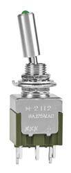
| 描述 | SWITCH TOGGLE SPDT 6A 125V |
| 产品分类 | |
| 品牌 | NKK Switches |
| 数据手册 | |
| 产品图片 |
|
| 产品型号 | M2112TFW01 |
| rohs | 无铅 / 符合限制有害物质指令(RoHS)规范要求 |
| RoHS指令信息 | |
| 产品系列 | M2100 |
| 产品培训模块 | http://www.digikey.cn/PTM/IndividualPTM.page?site=cn&lang=zhs&ptm=7079http://www.digikey.cn/PTM/IndividualPTM.page?site=cn&lang=zhs&ptm=13399http://www.digikey.cn/PTM/IndividualPTM.page?site=cn&lang=zhs&ptm=30248http://www.digikey.cn/PTM/IndividualPTM.page?site=cn&lang=zhs&ptm=30583 |
| 产品目录绘图 |
|
| 产品目录页面 | |
| 侵入防护 | - |
| 其它名称 | 360-2313 |
| 包装 | 散装 |
| 安装类型 | 面板安装 |
| 工作温度 | -10°C ~ 55°C |
| 开关功能 | 开-开 |
| 标准包装 | 1 |
| 照明 | 发光 |
| 照明电压(标称值) | 2.1 VDC |
| 照明类型,颜色 | LED,绿 |
| 特性 | 环氧树脂密封端子 |
| 电气寿命 | 25,000 次循环 |
| 电路 | SPDT |
| 端子类型 | 焊片 |
| 致动器材料 | - |
| 致动器类型 | 标准圆形 |
| 致动器长度 | 14.70mm |
| 衬套螺纹 | 1/4-40 |
| 面板开口尺寸 | 圆形 - 6.50mm 直径 |
| 额定电压-AC | 125V |
| 额定电压-DC | 30V |
| 额定电流 | 6A(AC),3A(DC) |


- 商务部:美国ITC正式对集成电路等产品启动337调查
- 曝三星4nm工艺存在良率问题 高通将骁龙8 Gen1或转产台积电
- 太阳诱电将投资9.5亿元在常州建新厂生产MLCC 预计2023年完工
- 英特尔发布欧洲新工厂建设计划 深化IDM 2.0 战略
- 台积电先进制程称霸业界 有大客户加持明年业绩稳了
- 达到5530亿美元!SIA预计今年全球半导体销售额将创下新高
- 英特尔拟将自动驾驶子公司Mobileye上市 估值或超500亿美元
- 三星加码芯片和SET,合并消费电子和移动部门,撤换高东真等 CEO
- 三星电子宣布重大人事变动 还合并消费电子和移动部门
- 海关总署:前11个月进口集成电路产品价值2.52万亿元 增长14.8%


PDF Datasheet 数据手册内容提取
Series M2100 LED Tipped Toggles s e glA g General Specifications o T s er k c o Electrical Capacity (Resistive Load) R Power Level (silver): 6A @ 125V AC or 3A @ 250V AC or 3A @ 30V DC s Logic Level (gold): 0.4VA maximum @ 28V AC/DC maximum n utto (Applicable Range 0.1mA ~ 0.1A @ 20mV ~ 28V) b Note: Find additional explanation of operating range in Supplement section. h s u P Other Ratings B P d Contact Resistance: 10 milliohms maximum for silver; 20 milliohms maximum for gold e at Insulation Resistance: 1,000 megohms minimum @ 500V DC n mi Dielectric Strength: 1,000V AC minimum between contacts for 1 minute minimum; u Ill 1,500V AC minimum between contacts & case for 1 minute minimum e bl Mechanical Life: 50,000 operations minimum a m Electrical Life: 25,000 operations minimum m gra Nominal Operating Force: On-to-On Position Off-to-On Position o Pr Single Pole 3.19N 3.92N Double Pole 4.41N 7.06N ks Angle of Throw: 20° c o yl e K Materials & Finishes Bushing: Brass with nickel plating s Housing: Stainless steel e ari Mounting Bracket: Steel with tin plating Rot Movable Contacts: Silver alloy or silver alloy with gold plating Stationary Contacts: Silver with silver plating or copper or brass with gold plating Lamp Contacts: Phosphor bronze es Base: Diallyl phthalate (UL94V-0) d Sli Switch Terminals: Copper with silver or gold plating Lamp Terminals: Brass with silver or gold plating s Environmental Data e ctil Operating Temp Range: –10°C through +55°C (+14°F through +131°F) a T Humidity: 90 ~ 95% humidity for 96 hours @ 40°C (104°F) Vibration: 10 ~ 55Hz with peak-to-peak amplitude of 1.5mm traversing the frequency range & returning in 1 minute; 3 right angled directions for 2 hours Tilt Shock: 50G (490m/s2) acceleration (tested in 6 right angled directions, with 5 shocks in each direction) Installation Mounting Torque: 1.47Nm (13 lb•in) for double nut; .67Nm (6 lb•in) for single nut h Soldering Time & Temp: Wave Soldering (PC version): See Profile B in Supplement section. c u o Manual Soldering: See Profile B in Supplement section. T Note: Lever must be in center position while soldering. Cleaning: PC mountable device is not process sealed. Hand clean locally using alcohol based solution. s or at Standards & Certifications c di n Flammability Standards: UL94V-0 base I UL: File No. E44145 - Recognized only when ordered with marking on switch. es Add “/U” to end of part number to order UL recognized switch. ori Single pole with synchronous circuits & single color LEDs & solder lug or PC recognized at s s ce 6A @ 125V AC. c A CSA: File No. 023535_0_000 - Certified only when ordered with marking on switch. nt Add “/C” to end of part number to order CSA certified switch. me All single pole with synchronous circuits & single color LEDs certified at 6A @ 125V AC. e pl p u S A76 www.nkk.com
Series M2100 LED Tipped Toggles s e A gl Distinctive Characteristics g o T s er k c o R Industry’s first LED illumination at tip of toggle switches. s n o Single color LEDs of red, yellow, and green, plus bicolor red/green, utt b h to meet varied design requirements. us P B P d LEDs can operate independently from or synchronously with e at switching operation. min u Ill e Antijamming feature to protect contacts from damage due abl m to excessive downward force on the toggle. m a gr o Pr High torque bushing prevents the bushing from rotating s or separating from the metal frame during installation. ck o yl e K Stainless steel frame resists corrosion. s e ari Silver contacts are of specially composed alloy for ot R hardness. s High insulating barriers protect against crossover de Sli in double pole devices. Terminals are molded in and epoxy sealed to lock es out flux, dust, and other contaminants. actil T 1,500V dielectric strength between switch contacts and case is accomplished by clinching the frame Tilt away from the terminals. Actual Size h c u o T s or at c di n I s e ori s s e c c A nt e m e pl p u S www.nkk.com A77
Series M2100 LED Tipped Toggles s e glA TYPICAL SWITCH ORDERING EXAMPLE g o T M21 1 2 T C W 01 s er k c o R s n o utt Poles LED Circuits & Contact Materials Threaded Bushings b sh Actuator Types & Ratings u 1 SPDT No 1/4–40 Thread P PB * 2 DPDT L Isolated W Silver; Rated Code (Inch) minated * TAevrmaiilnaabllse 0o1n,l y0 w2,i t0h 3 T Synchronous G 6GAol d@; R1a2te5dV 0 A.4CVA max /M 6(Mmemtr iTch)read u @ 28V AC/DC max Ill e bl a m m a ogr Circuits LED Colors Terminals & Mounting Types Pr 2 ON NONE ON Single Color 01 Solder Lug with Threaded Bushing s ck 3 ON OFF ON C Red 02 Quick Connect with Threaded Bushing o yl e E Yellow 03 Straight PC with Threaded Bushing K F Green Right Angle PC with Smooth Bushing 30 (available with gold contacts only) s Bicolor e otari CF Red/Green R s e d Sli IMPORTANT: Switches are supplied without UL & CSA marking unless specified. s actile USpL e&ci fiCcS Am oredceolsg, nriazteindg os,n &ly owrdheerni nogr dinesrterduc wtioitnhs maraer kniontge do no nth teh es w itch. T General Specifications page. Tilt DESCRIPTION FOR TYPICAL ORDERING EXAMPLE h M2112TCW01 c u o T Red LED ors Synchronous LED Circuit at in Actuator c ndi SPDT 1/4–40 Threaded Bushing I ON-NONE-ON s Switch Circuit e ori s Silver Contacts with s e c 6-Amp Rating c A Solder Lug Terminals nt e m e pl p u S A78 www.nkk.com
Series M2100 LED Tipped Toggles s e POLES & CIRCUITS & LED ILLUMINATION A gl g o T Toggle Position & Terminal Numbers Schematics Down Center Up Keyway Notes: Terminal numbers are not actually on the switch. ers LEDs require an external power source. k Model Pole & Throw oc R M2112 SPDT ON NONE ON Isolated 2 (COM) Connected Power Terminals 2-3 NONE 2-1 Single Color ns o Isolated LEDs (see schematics) ON NONE ON LED L(+) L(-) utt 3 1 4 6 b Circuit SynCcohnrnoencotueds SLEinDg lTee rCmoilnoar lLsED O4-N6 NNOONNEE O4-F6F Isolated 2 (COM) Red Push D Connected LED Terminals 4-6 NONE OPEN Bicolor LED Green PB E d L Synchronous Bicolor LED Red NONE Green (+) Red e 3 1 4 COM 6 ( ) Green at Connected LED Terminals 5-6 NONE 5-4 n mi M2113 SPDT ON OFF ON Synchronous 2 (COM) Illu Connected Power Terminals 2-3 OPEN 2-1 Single Color e L(+) L(-) bl LED a Isolated LEDs (see schematics) ON ON ON 3 1 4 6 m m Circuit SynCcohnrnoencotueds SLEinDg lTee rCmoilnoar lLsED O4-N6 O4-F6F O4-N6 Synchronous 2 (COM) Red Progra D Connected LED Terminals 4-6 OPEN 4-6 Bicolor LED Green LE Synchronous Bicolor LED Red OFF Green 3 1 6 5COM (+) 4 ks c Connected LED Terminals 5-6 OPEN 5-4 External Connection ylo e M2122 DPDT ON NONE ON Isolated 2 (COM) 5 K Connected Power Terminals 2-3 5-6 NONE 2-1 5-4 Single Color uit IsoClaotnende LcEteDds L(EseDe Tsecrhmeimnaaltsics) O7-N9 NNOONNEE O7-N9 LED 3 1 6 4 7L(+) 9L(-) otaries D Circ SynCcohnrnoencotueds SLEinDg lTee rCmoilnoar lLsED O7-N9 NNOONNEE OOPFEFN IBsiocloaltoerd L ED 2 (COM) 5 RGereden R E L Synchronous Bicolor LED Red NONE Green (+) Red Connected LED Terminals 8-9 NONE 8-7 3 1 6 4 7 COM 9( ) Green des Sli M2123 DPDT ON OFF ON Synchronous 2 (COM) 5 Connected Power Terminals 2-3 5-6 OPEN 2-1 5-4 Single Color LED Isolated LEDs (see schematics) ON ON ON 3 1 6 4 7L(+) 9L(-) es rcuit SynCcohnrnoencotueds SLEinDg lTee rCmoilnoar lLsED O7-N9 O7-F9F O7-N9 Synchronous 2 (COM) 5 Tactil Ci Red D Connected LED Terminals 7-9 OPEN 7-9 Bicolor LED Green E L Synchronous Bicolor LED Red OFF Green 3 1 6 4 9 8COM (+) 7 Connected LED Terminals 8-9 OPEN 8-7 External Connection Tilt LED COLORS & SPECIFICATIONS The electrical specifications shown are determined at a basic temperature of 25°C. LED circuit is isolated and requires an external power source. If the h c source voltage exceeds the rated voltage, a ballast resistor is required. The resistor value can be calculated by using the formula in Supplement Section. u o T Single Color Bicolor The LED is an integral part of the switch and not available separately. s C E F CF or Bicolor LED is translucent white when unlit. at c Color Red Yellow Green Red/Green Units di n I Maximum Forward Current I 25 30 30 25 mA FM s Typical Forward Current IF 20 20 20 10 mA orie s Forward Voltage V 2.1 2.1 2.1 1.7/2.0 V es F c c Maximum Reverse Voltage V 4 4 4 ––– V A RM Current Reduction Rate Above 25°C ∆I 0.33 0.40 0.40 0.33/0.33 mA/°C nt F me Ambient Temperature Range –10° ~ +55°C ple p u S www.nkk.com A79
Series M2100 LED Tipped Toggles s e glA LED CIRCUIT, TOGGLE, & MOUNTING TYPE COMBINATIONS g o T L 20° 20° Max. Panel Max. Panel Toggle with Isolated LED Circuit ers (.519.07) Dia (.519.07) Dia Thickness with Thickness without ock T Standard Hardware Locking Ring R Toggle with Synchronous LED Circuit .102” (2.6mm) .134” (3.4mm) (14.7) (14.7) .579 .579 s Finish: Brushed aluminum n o (5.6) shbutt SNtautnsd, a1r dA TH5a0r7dHw aLorec:k i n2g A RTi5n1g3, H1 AHTe5x0 9 1/4-40 Thd (.62.424) Dia (.62.556) Dia .(265.56) (.62.556) Dia (0.6).220 Pu (2.2) Dia .024 Lockwasher Standard & optional Threaded Bushing Smooth Bushing .087 PB hardware details in Accessories & combines with Terminal combines with d e Hardware section. codes 01, 02, & 03. Terminal code 30. at n mi Illu TYPICAL SWITCH DIMENSIONS e bl a m Solder Lug Single Pole m a gr o Pr Keyway 1/4-40 Thd (4.8) (0.8) Typ .189 .031 s 6 3 k c ylo 20° (4.7) Typ 5 2 (.1531.20) Ke .185 4 1 (2.5) Dia .098 (5.0) Dia (0.9) (6.35) (1.17) Typ (2.0) Typ .197 .035 .250 .046 .079 es (12.7) (14.7) (8.0) (20.3) (4.8) ari .500 .579 .315 .799 .189 ot R M2112TCFW01 Single color LED switch does not have terminal 5. s e d Solder Lug Double Pole Sli (.62.5305) Keyway 1/4-40 Thd (.418.89) (.00.381) Typ es 9 6 3 Tactil 20° (4.7) Typ 8 5 2 (.1531.20) .185 7 4 1 (2.5) Dia .098 (5.0) Dia (0.9) (6.35) (1.17) Typ (2.0) Typ Tilt .197 (.1678.59) (.1547.97) (.83.105) .035 ( 2.709.93) .250 .046 (.41.80.897) 9Typ M2122TCFW01 Single color LED switch does not have terminal 8. h c u o Right Angle PC Single Pole Only T Keyway (2.5) Dia (6.2) Dia .098 .244 s or at 4 5 6 c di (5.0) Dia (12.7) In .197 1 2 3 .500 s (4.3) orie (.211.49) .169 ess .(015.45) (.00.146) cc (5.1) (1.1) (1.27) Typ (0.8) Typ A .201 .043 .050 .031 (13.0) (14.7) (7.6) (16.4) (3.81) (4.7) Typ .512 .579 .299 .646 .150 .185 nt e m e M2112TCFG30 Single color LED switch does not have terminal 5. Gold contact material only pl p u S A80 www.nkk.com
Series M2100 LED Tipped Toggles s e CONTACT MATERIALS & RATINGS A gl g o T W Silver over Silver Power Level 6A @ 125V AC & 3A @ 250V AC s er k c o R G Gold over Brass or Copper Logic Level 0.4VA maximum @ 28V AC/DC maximum s Complete explanation of operating range in Supplement section. n o utt b TERMINALS sh u P B P 01 Solder Lug with (2.0) 02 ed Turret LED Terminal Epoxy Seal .079 Quick Connect at n (6.2.3550)(.418.89) (2.0) (.415.07) (6.2.3550) (.418.89) (1.E5p7o) xTyy pSeal Illumi (1.17) .079 .062 e .046 (4.8) .0(14.13) (.418.89) mabl .189 Thk = (0.8) Typ m T h k = .(003.81) Typ .031 gra o Pr 03 Straight PC with Turret LED Terminal Single Pole Double Pole cks o yl (4.8) (4.8) Typ Ke .189 Single color LED .189 Single color LED 3 6 3 6 9 (6.2.3550)(.418.89) (1.E1p7o) Txyyp Seal 2 5 (.418.75) Typ &LE Dis oslwatietcdh ebsi cdoolo nr o t 2 5 8 (.418.75) Typ &LE Dis oslwatietcdh ebsi cdoolo nr o t es (4.8) .046 1 4 have terminal 5. 1 4 7 have terminal 8. ari .189 ot Thk = (0.8) Typ (1.8) Dia Typ (.10.783) Dia Typ R .031 .073 Single Pole s e (.418.75) Typ Slid 30 (3.81) Right Angle PC 6 5 4 .150 Single color LED 3 2 1 & isolated bicolor es LED terminals (16.4) LED switches do not actil only available .646 have terminal 5. T in brass with silver plating (1.8) Dia Typ .073 (.210.504) Typ Tilt STANDARD MOUNTING HARDWARE h c u AT513H AT507H AT509 To Hexagon Nuts (2 per switch) Locking Ring (1 per switch) Lockwasher (1 per switch) Material: Brass with nickel plating Material: Steel with chromate over zinc Material: Steel with chromate over zinc s (6.35) Dia or .250 at 1/4-40 Thd c di n (.83.105) (2.0) (.1427.20) Dia (.62.542) Dia (.1400.22) Dia I .079 es ori (5.5) or ss .229 e c c A (9.0) (1.5) (1.7) (0.8) (0.5) .354 .059 .067 .031 .020 nt e m Optional Hardware: Knurled nuts, dress nuts, and ON-OFF plates are available; see details in Accessories & Hardware section. e pl p u S www.nkk.com A81
Series M2100 LED Tipped Rockers & Paddles s e gl General Specifications g o T s ker B Electrical Capacity (Resistive Load) c Ro Power Level (silver): 6A @ 125V AC or 3A @ 250V AC or 3A @ 30V DC Logic Level (gold): 0.4VA maximum @ 28V AC/DC maximum s (Applicable Range 0.1mA ~ 0.1A @ 20mV ~ 28V) n utto Note: Find additional explanation of operating range in Supplement section. b h s u Other Ratings P B Contact Resistance: 10 milliohms maximum for silver; 20 milliohms maximum for gold P d Insulation Resistance: 1,000 megohms minimum @ 500V DC e at Dielectric Strength: 1,000V AC minimum between contacts for 1 minute minimum; n mi 1,500V AC minimum between contacts & case for 1 minute minimum u Ill Mechanical Life: 50,000 operations minimum e bl Electrical Life: 25,000 operations minimum a m Nominal Operating Force: On-to-On Position Off-to-On Position m gra Paddles Single Pole 3.19N 3.92N o Pr Double Pole 4.41N 7.06N Rockers Single Pole 6.37N 9.80N ks Double Pole 13.73N 17.65N c o yl Angle of Throw: 20° e K Materials & Finishes s Housing: Stainless steel e ari Mounting Bracket: Steel with tin plating Rot Movable Contacts: Silver alloy or silver alloy with gold plating Stationary Contacts: Silver with silver plating or copper or brass with gold plating Lamp Contacts: Phosphor bronze es Base: Diallyl phthalate (UL94V-0) d Sli Switch Terminals: Copper with silver or gold plating Lamp Terminals: Brass with silver or gold plating s Environmental Data e ctil Operating Temp Range: –10°C through +55°C (+14°F through +131°F) for rockers a T –25°C through +70°C (–13°F through +158°F) for paddles Humidity: 90 ~ 95% humidity for 96 hours @ 40°C (104°F) Vibration: 10 ~ 55Hz with peak-to-peak amplitude of 1.5mm traversing the frequency range & returning Tilt in 1 minute; 3 right angled directions for 2 hours Shock: 50G (490m/s2) acceleration (tested in 6 right angled directions, with 5 shocks in each direction) Installation h Soldering Time & Temp: Wave Soldering (PC version): See Profile B in Supplement section. c u o Manual Soldering: See Profile B in Supplement section. T Note: Lever must be in center position while soldering. Cleaning: PC mountable device is not process sealed. Hand clean locally using alcohol based solution. s or at Standards & Certifications c di n Flammability Standards: UL94V-0 base I UL: File No. E44145 - Recognized only when ordered with marking on switch. es Add “/U” before dash in part number to order UL recognized switch. ori Single pole rockers with synchronous circuits & single color LEDs & solder lug or PC s s ce recognized at 6A @ 125V AC. c A CSA: File No. 023535_0_000 - Certified only when ordered with marking on switch. nt Add “/C” before dash in part number to order CSA certified switch. me All single pole rockers with synchronous circuits & single color LEDs certified at 6A @ 125V AC. e pl p u S B92 www.nkk.com
Series M2100 LED Tipped Rockers & Paddles s e TYPICAL SWITCH ORDERING EXAMPLE gl g o T M21 1 2 N C F W 01 s B ker c o R s Poles LED Colors Contact Materials on & Ratings utt 1 SPDT Single Color b h s * 2 DPDT C Red W Silver; Rated Pu 6A @ 125V AC B * Available only with Rockers E Yellow P with Terminals 01, 02, 03 F Green G G@o 2ld8; VR aAteCd/ 0D.4CV Am amxax nated mi Bicolor u Ill CF Red/Green e bl Circuits a m m 2 ON NONE ON gra o 3 ON OFF ON Pr s k c LED Circuits & Terminals & ylo e Actuator Types Mounting Types K Rocker 01 Solder Lug with Flat Frame s e R Isolated 02 Quick Connect with Flat Frame ari ot R N Synchronous 03 Straight PC with Flat Frame 13 Straight PC with Bracket Mount s Optional Bezel de Paddle 01 Solder Lug with Snap-in Frame & Colors Sli P Isolated 02 Quick Connect with Snap-in Frame For Snap-in Frame J Synchronous 03 Straight PC with Snap-in Frame A Black es 13 Straight PC with Bracket Mount B White actil T E Yellow IMPORTANT: F Green Switches are supplied without UL & CSA marking unless specified. G Blue Tilt UL & CSA recognized only when ordered with marking on the switch. Specific models, ratings, & ordering instructions are noted on the H Gray General Specifications page. h c u o T DESCRIPTION FOR TYPICAL ORDERING EXAMPLE M2112NCFW01 s or at c di Red/Green LED n I SPDT Synchronous LED Circuit es ON-NONE-ON in Rocker Actuator ori s Switch Circuit es c c Silver Contacts with A 6-Amp Rating Solder Lug Terminals ent m e pl p u S www.nkk.com B93
Series M2100 LED Tipped Rockers & Paddles s e gl POLES & CIRCUITS & LED ILLUMINATION g o T Toggle Position & Terminal Numbers Schematics Down Center Up Model Pole & Throw kers B Notes: TLeErDms inreaql uniurem abne resx aterern naol tp aocwtuear llsyo uornc eth.e switch. c o R M2112 SPDT ON NONE ON Isolated 2 (COM) ns Connected Power Terminals 2-3 NONE 2-1 Single Color butto Isolated LEDs (see schematics) ON NONE ON LED 3 1 L(+)4 6L(-) Push Circuit SynCcohnrnoencotueds SLEinDg lTee rCmoilnoar lLsED O4-N6 NNOONNEE O4-F6F Isolated 2 (COM) Red PB D Connected LED Terminals 4-6 NONE OPEN Bicolor LED Green ed LE Synchronous Bicolor LED Red NONE Green (+) Red at 3 1 4 COM 6 ( ) Green n Connected LED Terminals 5-6 NONE 5-4 mi Illu M2113 SPDT ON OFF ON Synchronous 2 (COM) e Connected Power Terminals 2-3 OPEN 2-1 Single Color bl L(+) L(-) a LED m Isolated LEDs (see schematics) ON ON ON 3 1 4 6 m Progra Circuit SynCcohnrnoencotueds SLEinDg lTee rCmoilnoar lLsED O4-N6 O4-F6F O4-N6 Synchronous 2 (COM) Red D Connected LED Terminals 4-6 OPEN 4-6 Bicolor LED Green ks LE Synchronous Bicolor LED Red OFF Green 3 1 6 5COM (+) 4 c ylo Connected LED Terminals 5-6 OPEN 5-4 External Connection e K M2122 DPDT ON NONE ON Isolated 2 (COM) 5 Connected Power Terminals 2-3 5-6 NONE 2-1 5-4 Single Color es Isolated LEDs (see schematics) ON NONE ON LED 3 1 6 4 7L(+) 9L(-) otari uit Connected LED Terminals 7-9 NONE 7-9 R rc Synchronous Single Color LED ON NONE OFF Isolated 2 (COM) 5 D Ci Connected LED Terminals 7-9 NONE OPEN Bicolor LED RGereden LE Synchronous Bicolor LED Red NONE Green (+) Red s 3 1 6 4 7 COM 9( ) Green de Connected LED Terminals 8-9 NONE 8-7 Sli M2123 DPDT ON OFF ON Synchronous 2 (COM) 5 Connected Power Terminals 2-3 5-6 OPEN 2-1 5-4 Single Color LED L(+) L(-) es Isolated LEDs (see schematics) ON ON ON 3 1 6 4 7 9 Tactil rcuit SynCcohnrnoencotueds SLEinDg lTee rCmoilnoar lLsED O7-N9 O7-F9F O7-N9 Synchronous 2 (COM) 5 Ci Red D Connected LED Terminals 7-9 OPEN 7-9 Bicolor LED Green E L Synchronous Bicolor LED Red OFF Green 3 1 6 4 9 8COM (+) 7 Tilt Connected LED Terminals 8-9 OPEN 8-7 External Connection LED COLORS & SPECIFICATIONS Rockers Paddles h The electrical specifications shown are determined at a basic c u To temperature of 25°C. LED circuit is isolated and requires an Single Color Bicolor Single Color Bicolor external power source. If the source voltage exceeds the rated voltage, a ballast resistor is required. The resistor value can be s calculated by using the formula in Supplement Section. The LED C E F CF C E F CF ator is an integral part of the switch and not available separately. dic Bicolor LED is translucent white when unlit. Red Yellow Green Red/Green Red Yellow Green Red/Green Units n I Maximum Forward Current I 25 30 30 25 25 30 25 30/25 mA FM s orie Typical Forward Current IF 20 20 20 20 20 20 20 20/20 mA s es Forward Voltage V 2.1 2.1 2.1 1.7/2.0 2.25 2.1 2.2 2.0/2.2 V cc F A Maximum Reverse Voltage V 4 4 4 ––– 5 5 5 ––– V RM ent Current Reduction Rate Above 25°C ∆I 0.33 0.40 0.40 0.33/0.33 0.33 0.40 0.33 0.43/0.38 mA/°C m F e pl Ambient Temperature Range –10° ~ +55°C –25° ~ +70°C p u S B94 www.nkk.com
Series M2100 LED Tipped Rockers & Paddles s e LED CIRCUIT, ROCKER, & MOUNTING TYPE COMBINATIONS gl g o T R RIsooclakteerd w LiEthD Circuit (13.5( )1.666.81) (13.5(.)1666.18) Maxim.1u2m6 ”P a(3n.e2l mThmic)kness s N Rocker with .531 20° .531 20° B ocker Synchronous LED Circuit R Material: Polyamide .(398.86) (.1427.20) .(398.86) (.1427.20) (.1770.18) ns (23.8) o .937 utt Finish: Matte (0.6) (3.5) (3.5) hb .024 .138 .138 s u P Color: Black Flat Frame combines with Bracket combines with (2.6) Dia Typ .102 B Terminal codes 01, 02, & 03. Terminal code 13. (.1309.81) d P e at n TYPICAL ROCKER SWITCH DIMENSIONS mi u Ill Single Pole Solder Lug e bl .(029.44) Dia Typ (.1427.20) .(002.64) mma a (4.8) (0.8) Typ ogr .189 .031 Pr 6 3 (23.8) ( 21.916.51 ).937 20° (.418.75) Typ 54 21 (.1531.20) eylocks K (2.5) Dia .098 s e (.10.4176) Typ (.20.709) Typ ari (6.9) (3.5) (6.35) (4.8) ot .272 .138 .250 .189 R (9.3) (9.8) (20.3) (12.7) .366 .386 .799 .500 Single color LED switch does not have terminal 5. M2112NCFW01 s e d Double Pole Solder Lug Sli (6.35) (2.4) Dia Typ .250 .094 (12.0) (0.6) .472 .024 (4.8) (0.8) Typ es .189 .031 ctil (23.8) 9 6 3 Ta .937 (29.5) 20° (4.7) Typ 8 5 2 (.1531.20) 1.161 .185 7 4 1 (2.5) Dia Tilt .098 (1.17) Typ (2.0) Typ .046 .079 (6.9) (3.5) (6.35) (4.8) Typ .272 .138 .250 .189 h .(396.36) .(398.86) ( 2.709.93) (.1678.59) ouc T Single color LED switch does not have terminal 8. M2122NCFW01 Single Pole Only Straight PC • Bracket s or (12.0) (4.5) (9.0) at .472 .177 (0.8) Typ 6.3543 (.312.26) Typ Directio Indic 20° (.418.75.)0 T3y1p (.1652.28) 45 12 (.1531.20) (1.770.81) n of Actua ssories tion cce (2.5) Dia (0.5) Typ (1.17) Typ (1.17) Typ (10.1) A .098 (3.5) (6.35) .020 .046 (4.8) .046 .398 .138 .250 .189 nt (9.3) (9.8) (20.3) (12.7) me .366 .386 .799 .500 e Single color LED switch does not have terminal 5. Silver contact material is standard. M2112NCFW13 ppl u S www.nkk.com B95
Series M2100 LED Tipped Rockers & Paddles s e gl LED CIRCUIT, PADDLE, & MOUNTING TYPE COMBINATIONS g o T P s Paddle with Isolated LED Circuit ker B Maximum Panel Thickness c o R .039” ~ .126” (1.0 ~ 3.2mm) Maximum without Bezel Panel ns J .039” ~ .098” (1.0 ~ 2.5mm) Thickness utto Paddle with Synchronous LED Circuit with Bezel .126” (3.2mm) b h s u P 20° 20° (3.2) (3.2) B .126 .126 Illuminated P MFCionalitosehrr::i a BlM:l a aPctotkelyamide (.1533.97) .(002.50) (.417 ..(25753).92) R (.1652.69) ( 2.709.11) (.41 .7.(25573).92) R (.1520.70) ble (7.1) (.1531.61) (.1429.40) ma .280 (2.8) m .110 (3.5) a .138 gr o Pr Snap-in combines with Terminal codes 01, 02, & 03 Bracket combines with Terminal code 13 s k c o eyl TYPICAL PADDLE SWITCH DIMENSIONS K Solder Lug • Snap-in Single Pole Only s e ari ot R (0.5) (4.8) .020 .189 (0.8) Typ .031 s 6 3 e (18.0) Slid .709 20° (4.7) Typ 5 2 (.1531.20) (2.0) .185 4 1 .079 (3.2) .126 s (5.0) (2.8) (1.17) Typ (2.0) Typ e .197 .110 .046 .079 actil (.1415.53) .(278.10) ( 6.2.3550) (.418.89) T (12.2) (13.7) (26.5) (12.7) .480 .539 1.043 .500 Tilt M2112JCFW01 Single color LED switch does not have terminal 5. Straight PC • Bracket Single Pole Only h c u o T (4.5) (9.0) .177 .354 (3.2) Typ .126 Indicators (2.0) 20° (.418.75(.)00 T.3y8p1) Ty(.p1652.28) 465 312 (.1531.20) .079 (3.2) es (5.0) .126 (0.5) Typ (1.17) Typ (1.17) Typ ori (9.1.907) (3.5) (6.35) .020 .046 (4.8) .046 ccess .35(.41415.53) ( 2.709.11) .138 ( 2.709.52) .250 (..151280.907) A nt e m e M2112JCFW13 Silver contact material is standard. Single color LED switch does not have terminal 5. pl p u S B96 www.nkk.com
Series M2100 LED Tipped Rockers & Paddles s e CONTACT MATERIALS & RATINGS gl g o T W Silver over Silver Power Level 6A @ 125V AC & 3A @ 250V AC s B ker c o R G Gold over Brass or Copper Logic Level 0.4VA maximum @ 28V AC/DC maximum ns o utt Complete explanation of operating range in Supplement section. b h s u P TERMINALS B P d e at n Solder Lug with mi 01 Turret LED Terminal Epoxy Seal (.20.709) 02 Quick Connect Illu (6.2.3550)(.418.89) (.415.07) (6.2.3550) (.418.89) Epoxy Seal mable (2.0) (1.57) Typ m (1.17) .079 .062 a .046 (1.1) (4.8) gr (.418.89) .043 Thk =. 1(08.98) Typ Pro Thk = (0.8) Typ .031 .031 s k c o yl 03 Straight PC with Ke Turret LED Terminal Single Pole Double Pole (4.8) (4.8) Typ es (6.2.3550)(.418.89) Epoxy Seal 23.189 56 (.418.75) Typ S&LEi nDisg oslelwa ctietocdlho ebrs iL cdEooDlo nr ot 23 56 89.1(.84198.75) Typ S&LEi nDisg oslelwa ctietocdlho ebrs iL cdEooDlo nr ot Rotari (1.17) Typ .046 1 4 have terminal 5. 1 4 7 have terminal 8. (4.8) T h k = . .1(0083.981) Typ (.10.783) Dia Typ (.10.783) Dia Typ Slides Single Pole Straight PC with Bracket 13 s & Turret LED Terminal .(016.63) T(2yp.4) Typ actile .095 T 3 6 Single color LED (7.9) Typ .311 & isolated bicolor 2 5 (4.7) Typ LED switches do not 1 4 .185 have terminal 5. Tilt (1.8) Dia Typ .073 CL .(015.59) Dia Typ h c u o OPTIONAL BEZEL & COLORS T s AT2107 Bezel for Snap-in Panel Frame or (11.8) at Material: Polyamide .465 (15.9) Indic (2.2) .626 .087 Finish: Matte s (15.6) (.1427.02) orie .614 (13.1) s (21.5) .516 es .846 c c A nt A B E F G H e Colors Available: Black White Yellow Green Blue Gray m e pl p u S www.nkk.com B97
Mouser Electronics Authorized Distributor Click to View Pricing, Inventory, Delivery & Lifecycle Information: N KK Switches: M2113PCFG02-A M2113RCFW02 M2112JCFG03-A M2113PCG01-H M2113JCG01-H M2113PCW02-A M2113RCW01 M2113NCFG03 M2113NCFG13 M2122NCFW01 M2113JFG02-A M2112JFW01-H M2113PCW01A M2112TCFW01/CUL M2112LCW03