ICGOO在线商城 > M2032TXG30-DC

 Datasheet下载
- 型号: M2032TXG30-DC
- 制造商: NKK Switches
- 库位|库存: xxxx|xxxx
- 要求:
| 数量阶梯 | 香港交货 | 国内含税 |
| +xxxx | $xxxx | ¥xxxx |
查看当月历史价格
查看今年历史价格
M2032TXG30-DC产品简介:
ICGOO电子元器件商城为您提供M2032TXG30-DC由NKK Switches设计生产,在icgoo商城现货销售,并且可以通过原厂、代理商等渠道进行代购。 提供M2032TXG30-DC价格参考以及NKK SwitchesM2032TXG30-DC封装/规格参数等产品信息。 你可以下载M2032TXG30-DC参考资料、Datasheet数据手册功能说明书, 资料中有M2032TXG30-DC详细功能的应用电路图电压和使用方法及教程。
| 参数 | 数值 |
| 3D型号 | http://www.nkkswitches.com/model.aspx?part=M2032TXG30-DC&vendor=digikey |
| 产品目录 | |
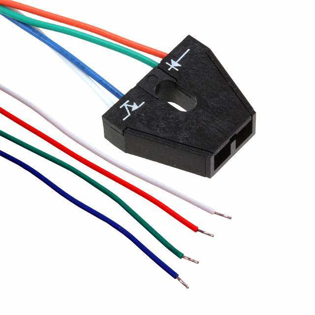
| 描述 | SWITCH ROCKER 3PDT 0.4VA 28V |
| 产品分类 | |
| 品牌 | NKK Switches |
| 数据手册 | |
| 产品图片 |
|
| 产品型号 | M2032TXG30-DC |
| rohs | 无铅 / 符合限制有害物质指令(RoHS)规范要求 |
| RoHS指令信息 | |
| 产品系列 | M |
| 产品培训模块 | http://www.digikey.cn/PTM/IndividualPTM.page?site=cn&lang=zhs&ptm=7079http://www.digikey.cn/PTM/IndividualPTM.page?site=cn&lang=zhs&ptm=30248 |
| 侵入防护 | - |
| 其它名称 | M2032TXG30DC |
| 包装 | 散装 |
| 安装类型 | 通孔,直角 |
| 工作温度 | -30°C ~ 85°C |
| 开关功能 | 开-开 |
| 机械寿命 | 50,000 次循环 |
| 标准包装 | 1 |
| 照明电压(标称值) | - |
| 照明类型,颜色 | - |
| 特性 | 环氧树脂密封端子 |
| 电气寿命 | 50,000 次循环 |
| 电路 | 3PDT |
| 端子类型 | PC 引脚 |
| 致动器标志 | 无标志 |
| 致动器样式 | 凹面(标准 V 形) |
| 面板开口尺寸 | - |
| 颜色-致动器/盖帽 | 红 |
| 额定电压-AC | 28V |
| 额定电压-DC | 28V |
| 额定电流 | 0.4VA(AC/DC) |


PDF Datasheet 数据手册内容提取
Series M Miniature Rockers s e gl g General Specifications o T s ker B Electrical Capacity (Resistive Load) c o R Power Level (silver): 6A @ 125V AC & 3A @ 250V AC 4A @ 30V DC for On-None-On; 3A @ 30V DC for all other circuits s on Logic Level (gold): 0.4VA maximum @ 28V AC/DC maximum utt (Applicable Range 0.1mA ~ 0.1A @ 20mV ~ 28V) b h s Logic/Power Level (gold over silver): Combines silver & gold ratings u P Note: Find additional explanation of dual rating & operating range in Supplement section. B P ed Other Ratings at n mi Contact Resistance: 10 milliohms maximum for silver; 20 milliohms maximum for gold u Ill Insulation Resistance: 1,000 megohms minimum @ 500V DC e Dielectric Strength: 1,000V AC minimum between contacts for 1 minute minimum; bl ma 1,500V AC minimum between contacts and case for 1 minute minimum m a Mechanical Life: 50,000 operations minimum gr o Electrical Life: 25,000 operations minimum for silver; 50,000 operations minimum for gold; Pr 50,000 operations minimum for silver at 3A @ 125V AC s Angle of Throw: 25° k c o eyl Materials & Finishes K Actuator Clip & Mounting Frame: Stainless Steel Body Frame: Stainless steel s arie Case: Diallyl phthalate resin (UL94V–0) ot Movable Contactor: Phosphor bronze with silver or gold plating R Movable Contacts: Silver alloy (code W); copper with gold plating (code G); or silver alloy with gold plating (code A) Stationary Contacts: Silver with silver plating (code W); copper or brass with gold plating (code G); s or silver with gold plating (code A) e Slid Terminals: Copper or brass with silver plating; or copper or brass with gold plating Environmental Data Operating Temp Range: –30°C through +85°C (–22°F through +185°F) s e ctil Humidity: 90 ~ 95% humidity for 96 hours @ 40°C (104°F) Ta Vibration: 10 ~ 55Hz with peak-to-peak amplitude of 1.5mm traversing the frequency range & returning in 1 minute; 3 right angled directions for 2 hours Shock: 50G (490m/s2) acceleration (tested in 6 right angled directions, with 5 shocks in each direction) Tilt Processing Soldering: Wave Soldering (PC version) for Gold: See Profile A in Supplement section. Manual Soldering for Gold: See Profile A in Supplement section. Wave Soldering (PC version) for Silver: See Profile B in Supplement section. h c Manual Soldering for Silver: See Profile B in Supplement section. u o T Note: Actuator must be in OFF (center) position while soldering. Cleaning: These devices are not process sealed. Hand clean locally using alcohol based solution. s or Standards & Certifications at c di Flammability Standards: UL94V–0 for case n I UL: File No. E44145 - Recognized only when ordered with marking on switch. Add “/U” or “/CUL ” before first dash in part number to order UL recognized switch. s e ori All models recognized at 6A @ 125V AC, 3A @ 250V AC or 0.4VA maximum @ 28V DC maximum. ss CSA: File No. 023535_0_000 - Certified only when ordered with marking on switch. e cc Add “/C” before first dash in part number to order CSA certified switch. A All models certified at 6A @ 125V AC or 3A @ 250V AC or 0.4VA maximum @ 28V maximum. nt e m e pl p u S B62 www.nkkswitches.com
Series M Miniature Rockers s e gl Distinctive Characteristics g o T s B ker c o R Three methods of panel mounting: flat frame for flush with face or subpanel, snap-in, and PCB. s n o utt b High insulating barriers increase isolation of circuits in multipole devices sh u P and provide added protection to contact points. B P d e The molded diallyl phthalate case has a UL 94V-0 nat mi flammability rating. u Ill e bl a Epoxy sealed terminals prevent entry of solder flux m m and other contaminants. gra o Pr Prominent external insulating barriers increase s k insulation resistance and dielectric strength. oc yl e K Bias guard prevents misalignment of contacts; interlocking of actuator block with rocker and es internal guide does not allow transmission of ari ot R diagonal force on rocker to reach contact mechanism. s e d Clinching of the frame to the case well above the base Sli and terminals provides 1,500V dielectric strength. s e ctil a T Tilt Actual Size h Snap-in Mount Page B64 uc o T s or at c di n Bracket PC Mount Page B72 I s e ori s s e c c A Flat Frame Mount Page B83 nt e m e pl p u S www.nkkswitches.com B63
Series M Bracket PC Mount Miniature Rockers s e gl TYPICAL SWITCH ORDERING EXAMPLE g o T s M20 1 3 TX G ker B c o R s n o utt b sh Poles Mounting Frames u P 1 SPDT Narrow Frame B TX d P DPDT for Small Actuator ate 2 SP3T Wide Frame min TZ for Large Actuator u 3PDT (used only Ill with terminal codes able 3 30 & 41 & frame m m code TX) a ogr 4PDT Pr DP3T 4 (used only with ks Circuits Contact Materials & Ratings c terminal code 41 & o Keyl frame code TX) 2 ON NONE ON W Silver; Rated 6A @ 125V AC & 3A @ 250V AC 3 ON OFF ON Gold; Rated es 5 ON NONE (ON) G 0.4VA max @ 28V AC/DC max ari 8 (ON) OFF (ON) ot Gold over Silver; Rated R 9 ON OFF (ON) A 6A @ 125V AC & 0.4VA max @ *4 ON ON ON 28V AC/DC max des *6 (ON) ON (ON) Sli *7 ON ON (ON) ( ) = Momentary es *3-ON circuits ctil a T Tilt h c ou DESCRIPTION FOR TYPICAL ORDERING EXAMPLE T M2013TXG41-DC s or at c di SPDT n I ON-OFF-ON Circuit Gold Contacts with s e ori 0.4VA Rating ss TX Frame with .365” (9.27mm) e cc Wide Red Rocker .150” (3.81mm) A Vertical PC Terminals with Support nt e m e pl p u S B72 www.nkkswitches.com
Series M Bracket PC Mount Miniature Rockers s e TYPICAL SWITCH ORDERING EXAMPLE gl g o T 41 D C s B ker c o R s n o utt b Terminals For Rockers Rocker & Paddle sh u TX & TZ Frames & Paddles Colors P B Straight PC with Bracket Small Actuators A Black d P (1-2 Pole only) (TX Frame) B White nate .250” (6.35mm) Straight PC with .365” (9.27mm) mi 13 .465” (11.8mm) Bracket D Wide Rocker C Red Illu 15 .425” (10.8mm) Straight PC with E .365” (9.27mm) E Yellow mable .630” (16.0mm) Bracket Wide Paddle F Green m a 17 .19.6145”0 ”( 2(42.95.m2mmm) )S tBrraaigckhet tPC with F .W45id0e” R(1o1ck.4e3rmm) G Blue Progr H Gray Straight PC with Reinforced Bracket G .450” (11.43mm) cks (1-2 Pole only) Wide Paddle o yl e .250” (6.35mm) Straight PC with Large Actuators K 23 .465” (11.8mm) Bracket (TZ Frame) 25 ..462350”” ((1106..80mmmm)) SBrtraacikgehtt PC with J .W59id5e” R(1o5ck.1e1rmm) aries ot .750” (19.05mm) Straight PC with .595” (15.11mm) R 26 H .953” (24.2mm) Bracket Wide Paddle s e d Terminals For Sli TX Frame Only Right Angle PC with Support IMPORTANT: s (1-3 Pole only) Switches are supplied without UL & CSA marking unless specified. ctile 30 .150” (3.81mm) Right Angle PC UL & CSA recognized only when ordered with marking on the switch. Ta Specific models, ratings and ordering instructions are noted on the Vertical PC with Support General Specifications page. (1-4 Pole) 41 .150” (3.81mm) Vertical PC Tilt h c DESCRIPTION FOR TYPICAL ORDERING EXAMPLE ou T M2022TZG23-JC s or at c TZ Frame with .595” (15.11mm) ndi I Wide Red Rocker s e ori Gold Contacts with 0.4VA Rating s DPDT es c ON-NONE-ON Circuit Ac .250” (6.35mm) Straight PC Terminals nt with Reinforced Bracket e m e pl p u S www.nkkswitches.com B73
Series M Bracket PC Mount Miniature Rockers s e gl POLES & CIRCUITS g o T Rocker Position ( ) = Momentary Connected Terminals Throw & Schematics s ker B Down Center Up Down Center Up Note: Terminal numbers are not actually c o R on the switch. Pole Model * Reverse circuits available for vertical s mount SP & DP upon request. n o utt b sh M2012 ON NONE ON SPDT u P M2013 ON OFF ON PB SP *M2015 ON NONE (ON) 2-3 OPEN 2-1 2 (COM) nated *MM22001189 (OONN ) OOFFFF ((OONN)) 3 1 mi u Ill M2022 ON NONE ON DPDT e bl M2023 ON OFF ON ma DP *M2025 ON NONE (ON) 2-3 5-6 OPEN 2-1 5-4 2 (COM) 5 m gra M2028 (ON) OFF (ON) 3 1 6 4 Pro *M2029 ON OFF (ON) ks M2022 ON NONE ON 3PDT c o M2023 ON OFF ON yl 2-3 5-6 2-1 5-4 Ke 3P *M2025 ON NONE (ON) OPEN 2 5 (COM) 8 8-9 8-7 M2028 (ON) OFF (ON) 3 1 6 4 9 7 *M2029 ON OFF (ON) s e otari M2042 ON NONE ON 4PDT R M2043 ON OFF ON 2-3 5-6 2-1 5-4 4P *M2045 ON NONE (ON) OPEN 2 5 (COM) 8 11 8-9 11-12 8-7 11-10 M2048 (ON) OFF (ON) s 3 1 6 4 9 7 12 10 de *M2049 ON OFF (ON) Sli For 3 Throw (3-On) s Connected Terminals & Schematics e ctil a Pole Model Down Center Up Down Center Up T External External External Connection Connection Connection Tilt SP MM22002246 (OONN) OONN (OONN) 2 (in) 5 2 (in) 5 2 (in) 5 M2027 ON ON (ON) 1 (out) 34 (out) 6 (out) 1 (out) 34 (out) 6 (out) 1 (out) 34 (out)6 (out) 2-3 5-6 2-3 5-4 2-1 5-4 h c u External External External External External External To Connection Connection Connection Connection Connection Connection 2 (in) 5 8 (in) 11 2 (in) 5 8 (in) 11 2 (in) 5 8 (in) 11 M2044 ON ON ON DP M2046 (ON) ON (ON) ors M2047 ON ON (ON) 1 (out) 34 (out)6 (out)7 (out)910 (out)12 (out) 1 (out) 34 (out)6 (out)7 (out)910 (out) 12 (out) 1 (out) 34 (out)6 (out)7 (out)910 (out)12 (out) at dic 2-3 5-6 2-3 5-4 2-1 5-4 n 8-9 11-12 8-9 11-10 8-7 11-10 I s e The SP3T model utilizes a The DP3T model utilizes a sori double pole base. (out) four pole base. (out) (out) es External 6 3 External cc Conn Conn 12 9 6 3 Common Aement Emxatedren adlu crionngn fiecetlido nin mstaulslta btioe n. (out)54 21(ouC(ti)no)mmon Emxatedren adlu crionngn fiecetlido nin mstaulslta btioe n. (C(oinou)mt)mon (11o01ut) 87 45(ou2t1) ((oinu)t) pl p u S B74 www.nkkswitches.com
Series M Bracket PC Mount Miniature Rockers s e MOUNTING FRAMES gl g o T Narrow Mounting Frame for Small Actuators TX with Straight PC Terminals (codes 13, 15, 17, 23, 25, & 26) s or with Angle PC Terminals (codes 30 & 41) B ker c o Straight PC Mounting Right Angle PC Mounting Vertical PC Mounting R s n o 25° ( 5.2.0080) 25° 25° hbutt s (2.54) Dia (2.54) Dia (2.54) Dia Pu .100 (1.4) Typ .100 .100 .055 B (.83.105) (.313.58) ( 4.1.7327) (.00.146) Typ (2.75) (1.27) ed P (5.08) .108 (6.0) .050 at .200 .235 min u Ill e Small Actuators & Panel Cutouts for TX Frame (actuator details on the following pages) bl a m m a AT4148 AT4149 AT4150 AT4151 gr o D D Pr ire ire ctio ctio ks (1.770.81) n of Actu (.1520.70) n of Actu Keyloc a a tion (12.4) tion (10.1) .490 s .398 e ari ot R Wide Mounting Frame Large Actuators & Panel Cutouts for TZ Frame TZ for Large Actuators (actuator details on the following pages) with Straight PC Terminals s e (codes 13, 15, 17, 23, 25, & 26) Slid AT4156 AT4157 25° (12.182.25) Direction of A Tactiles (2.54) Dia ctu .100 atio (3.5) n .138 Tilt (16.0) .630 CONTACT MATERIALS & RATINGS h c u o T W Silver over Silver Power Level 6A @ 125V AC & 3A @ 250V AC s or at G dic Gold over Brass or Copper Logic Level 0.4VA maximum @ 28V AC/DC maximum n I Note: See Supplement section to find complete explanation of operating range. s e ori s s A Power Level 6A @ 125V AC ce Gold over Silver or Logic Level or 0.4VA maximum @ 28V AC/DC maximum Ac Note: This dual rated option is suitable when two or more identical switches are used in logic and in power circuits within the ent m same application. See Supplement section to find complete explanation of dual rating and operating range. e pl p u S www.nkkswitches.com B75
Series M Bracket PC Mount Miniature Rockers s e gl TERMINALS g o T For TX and TZ 1-2 Pole For TX and TZ 1-2 Pole Straight PC Mount with Bracket Straight PC Mount with Reinforced Bracket s ker B c Ro 13 15 17 23 25 26 ns .250” (6.35mm) .425” (10.8mm) .964” (24.5mm) .250” (6.35mm) .425” (10.8mm) .750” (19.05mm) o utt Terminal with Terminal with Terminal with Terminal with Terminal with Terminal with hb .465” (11.8mm) .630” (16.0mm) 1.150” (29.2mm) .465” (11.8mm) .630” (16.0mm) .953” (24.2mm) s Pu Bracket Bracket Bracket Bracket Bracket Bracket B P d e at n mi u Ill e bl a m m a gr o Pr s ck PCB footprints are on the following Typical Switch Dimension pages. o yl e K For TX 1-3 Pole Right Angle PC Mount For TX 1-4 Pole Vertical PC Mount .150” (3.81mm) .150” (3.81mm) s 30 41 arie Right Angle PC Vertical PC ot R s e d Sli ROCKERS & PADDLES FOR TX MOUNTING FRAMES AT4148 .365” (9.27mm) AT4149 .365” (9.27mm) D E es Wide Rocker Wide Paddle ctil (.93.6257) (.20.8134) Ta Material: Polyamide Material: Polyamide (9.27) (16.87) Finish: Matte .365 .664 Finish: Matte (3.96) (13.49) .156 .531 (18.8) .740 (8.43) R Tilt (7.9) (6.15) .(384.86) .332 .311 .242 (3.5) (3.5) .138 (16.8) .138 .661 h c u o T AT4150 .450” (11.43mm) AT4151 .450” (11.43mm) F G Wide Rocker Wide Paddle (11.43) (2.36) dicators MFinaitsehr:i a Ml: aPtotelyamide (1.41.5403) (9.(.114916.)85) MFinaitsehr:i a Ml: aPtotelyamide .450 .093(3.1.2185) In .362 (1.66.4346) (5.84) R ories .(381.19) .(264.38) .(370.73) .230 s cces (.313.58) (11.8) (.313.58) A .465 nt e Cap Colors m A B C E F G H ple Available: Black White Red Yellow Green Blue Gray p u S B76 www.nkkswitches.com
Series M Bracket PC Mount Miniature Rockers s e ROCKERS & PADDLES FOR TZ MOUNTING FRAMES gl g o T AT4156 .595” (15.11mm) AT4157 .595” (15.11mm) J H Wide Rocker Wide Paddle s B ker Material: Polyamide Material: Polyamide c o Finish: Matte Finish: Matte R (14.33) (2.36) .564 .093 ns o utt b h (15.11) (4.1.8775) Pus .595 (26.78) (29.82) B 1.054 (2.930.061) 1.174 (13.5) R ed P .531 at (.83.341) .(265.56) (.1413.03) .(278.37) Illumin e (3.5) (3.5) abl .138 (15.11) (26.8) .138 m .595 1.055 m a gr o Pr Cap Colors A B C E F G H Available: Black White Red Yellow Green Blue Gray ks c o yl e OPTIONAL SNAP-IN PANEL FRAMES K Used with AT4148 Rocker and AT4149 Paddle s e ari AATc0co6m4-m1odates .047” ~ .090” AATc0co6m4-m2odates .062” ~ .125” (17.9) .(399.90) .(029.30) Rot .705 (1.2 ~ 2.3mm) panel thickness (1.57 ~ 3.18mm) panel thickness s e Material: Polyamide d Finish: Matte (15.62) (25.04) Sli .615 .986 Color: Black (6.68) .263 Mounted separately from switches A ctiles a Cutout Tolerances: T Dimension A: .797” ~ .803” (20.24 ~ 20.4mm) B Dimension B: .495” ~ .505” (12.57 ~ 12.83mm) Tilt AT064–1 Enlarged Detail Used with AT4150 Rocker and AT4151 Paddle h c AT065-1 AT065-2 u (12.0) (2.3) o Accommodates .047” ~ .090” Accommodates .062” ~ .125” (12.8) .472 .090 T .504 (1.2 ~ 2.3mm) panel thickness (1.57 ~ 3.18mm) panel thickness s Material: Polyamide (1 5.6.6152) (19.43) ator Finish: Matte .765 dic Color: Black (6.68) In .263 s Mounted separately from switches e A ori s s Cutout Tolerances: ce c Dimension A: A B .595” ~ .605” (15.11 ~ 15.37mm) nt Dimension B: e m .495” ~ .500” (12.57 ~ 12.7mm) AT065–1 Enlarged Detail AT065–2 Enlarged Detail ple p u S www.nkkswitches.com B77
Series M Bracket PC Mount Miniature Rockers s e gl TYPICAL SWITCH DIMENSIONS g o T Straight PC • Bracket 25° s ker B Single Double Roc (.62.4125) .(384.86) Pole Pole s Circuit Mark n (3.5) This Side butto .138 B LREANCGKTEHT h s u TERMINAL P LENGTH (4.8) Typ 1 2 3 .189 B ed P (.00.250) Typ (.10.4176) Typ (.418.89) at (0.8) Typ (1.17) Typ (3.2) Typ min .(40.371) Typ .046 (8.0) (12.7) .126 u .185 .315 .500 Ill (15.8) .622 e abl M2012TXG13-DC m m a gr o Pr Terminal Terminal Bracket (1.6) Typ .063 Code: Length: Length: (1.6) Typ (2.4) Typ ks .063 .095 c Keylo 13 .250” (6.35mm) .465” (11.8mm) (.73.191) Typ 23 (.73.191) Typ 23 56 (4.7) Typ (4.7) Typ .185 1 .185 1 4 15 .425” (10.8mm) .630” (16.0mm) (1.8) Dia Typ (1.8) Dia Typ es .073 .073 otari 17 .964” (24.5mm) 1.150” (29.2mm) .(015.59) Dia Typ . 0(15.59) Dia Typ CL R es Straight PC • Reinforced Bracket d Sli 25° (8.8) Single Double ctiles (.62.4125) .346 Pole Pole a T Circuit Mark (3.5) This Side .138 BRACKET LENGTH Tilt T LEERNMGITNHAL 1 2 3 (.418.89) Typ (0.5) Typ (1.17) Typ (6.35) Typ .020 .046 .250 (0.8) Typ (1.17) Typ (4.8) .031 .046 .189 h (4.7) Typ (9.1) (12.7) uc .185 (19.05) .358 .500 To .750 M2012TXG23-DC s or at (2.4) Typ Indic TeCromdine:al TLeernmgitnha:l BLerangckthe:t ( 3.1.2185) Typ ( 3.1.2185). 0Ty9p5 (9.53) Typ 3 (9.53) Typ 3 6 ories 23 .250” (6.35mm) .465” (11.8mm) .375 2 .375 2 5 ess (.418.75) Typ 1 (.418.75) Typ 1 4 c 25 .425” (10.8mm) .630” (16.0mm) c A (1.8) Dia Typ (1.8) Dia Typ .073 .073 ent 26 .750” (19.05mm) .953” (24.2mm) .(015.59) Dia Typ .(015.59) Dia Typ CL m e pl p u S B78 www.nkkswitches.com
Series M Bracket PC Mount Miniature Rockers s e TYPICAL SWITCH DIMENSIONS gl g o T Single Pole .150” (3.81mm) Right Angle PC s B ker c o R Shown in Down Position Pivot (4.7) Typ 1 2 3 .185 ns (5.41) (.93.6257) (.73.191) 3 2 1 utto .213 (.416.39) (.1520.07) ushb (0.4) P ( 2.1.1825 .)(015.45(5) T.0yp8) (8 (.6..208.411)526) .(25(.1.41575.)0(71)2.7) (.10.2570) (13.0) (.(.00418.3.8751)) TTyypp (.210.50.(410.)78 T3)y Dpia Typ nated PB .200 .346 .500 .512 mi u Ill e bl a m m a M2012TXG30-DC gr o Pr Double Pole .150” (3.81mm) Right Angle PC s k c o yl e K Shown in Down Position Pivot es (.418.75) Typ ari 4 5 6 6 5 4 ot (9.27) (12.7) (3.81) R (6.4) .365 1 2 3 .500 3 2 1 .150 .252 (4.3) (12.7) .169 .500 s e (2.1.81 .2(0515.)45) Typ (.62.4152) (.(.41005..10476)) Typ (.10.5207) Typ (.(.00418.3.8751)) TTyypp (1.8) D( i2.a1.0 5T04yp) Typ Slid (5.08) (8.8) (12.7) (3.81) (13.0) .073 .200 .346 .500 .150 .512 s e ctil a T M2022TXG30-DC Three Pole .150” (3.81mm) Right Angle PC Tilt Shown in h Down Position Pivot uc (4.7) Typ To .185 7 8 9 9 8 7 (3.81) Typ (9.27) (17.5) 6 5 4 .150 .(384.86) .365 14 25 63 .689 3 2 1 ators c (4.3) (14.35) di .169 .565 In (2.85) (0.4) (0.8) Typ .112 .016 .031 s .(015.45) Typ (.62.4152) (.417.57) (.10.5207) Typ (.418.75) Typ ( 2.1.0504) Typ orie (5.2.0080) .(384.86) (1.45.6355) ( 3.1.5801) Typ (1.531.02) .(017.83) Dia Typ cess c A nt e m M2032TXG30-DC e pl p u S www.nkkswitches.com B79
Series M Bracket PC Mount Miniature Rockers s e gl TYPICAL SWITCH DIMENSIONS g o T .150” (3.81mm) Vertical PC Single Pole s cker B (.93.6257) .(384.86) (.313.58) o R 3 (3.81) Typ ns 25° ( 1.531.02) 2 .150 butto .(396.10) ( 3.1.2185) 1 h (12.7) us .500 P (0.4) Typ (2.74) (1.27) (0.8) Typ (1.27) B .016 .108 .050 .031 .050 nated P (.52.0008) SDhoowwnn P ionsition (.62.4152) ( 5.2.9375) (.1520.07) ( 3.1.5801) Typ (.73.191) . 0(17.83) D( 2.i1a.05 T04y)p Typ mi M2012TXG41-DC u Ill e bl .150” (3.81mm) Vertical PC Double Pole a m m ogra (.93.6257) .(384.86) (.313.58) Pr (2.4) Typ .094 6 3 3 6 ocks 25° 5 2 ( 1.531.02) 2 5 (.315.801) Typ Keyl .(396.10) ( 3.1.2185) 4 1 1 4 (12.7) .500 (1.27) Typ .050 s (0.4) Typ (2.74) (1.27) (0.8) Typ (4.8) arie .016(5.08) Show .1n0 8in (6.15) (5.97) .0 (5120.7) (.30.3811) Typ (.1128.97) (.210.504) Typ ot .200 Down Position .242 .235 .500 .150 .500 (1.8) Dia Typ R .073 M2022TXG41-DC es .150” (3.81mm) Vertical PC Three Pole d Sli (9.27) (8.8) (3.5) .365 .346 .138 (4.8) Typ es 9 6 3 3 6 9 .189 actil 25° 8 5 2 ( 1.531.02) 2 5 8 ( 3.1.5801) Typ T (9.1) 7 4 1 1 4 7 .360 (3.18) .125 (14.35) (1.27) Typ .565 Tilt .(00.146) Typ ( 2.1.0784) (.10.5207) (.00.381) Typ (.418.89) Typ .050 (5.08) Shown in (6.15) (5.97) (14.35) (3.81) Typ (17.5) (2.54) Typ . 2 00 Down Position .242 .235 .565 .150 .689 .100 (1.8) Dia Typ .073 M2032TXG41-DC h c u o .150” (3.81mm) Vertical PC Four Pole T (9.27) (8.8) (3.5) ors .365 .346 .138 at (4.8) Typ dic 12 9 6 3 3 6 9 12.189 n (3.81) Typ I 25° 11 8 5 2 (.1531.20) 2 5 8 11 .150 es .(396.10) (3.18) 10 7 4 1 1 4 7 10 sori .125 (14.35) es .565 c c (0.4) Typ (2.74) (1.27) (0.8) Typ (4.8) Typ (1.27) Typ A .016 .108 .050 .031 .189 .050 (5.08) Shown in (6.15) (5.97) (14.35) (3.81) Typ (22.3) (2.54) Typ nt .200 Down Position .242 .235 .565 .150 .878 .100 e (1.8) Dia Typ m .073 e pl M2042TXG41-DC p u S B80 www.nkkswitches.com
Series M Bracket PC Mount Miniature Rockers s e TYPICAL SWITCH DIMENSIONS gl g o T Straight PC • Bracket 25° s (11.0) Single Double B cker .(266.60) .433 Pole Pole Ro (.313.58) CThiricsu Sitid Meark ons BLERNAGCTKHET butt h TERMINAL us LENGTH (4.8) Typ P 1 2 3 .189 (.(.0000..236841)) TTyypp .((101..411776)) TTyypp ((.3418..289)) Typ ated PB (.418.75) Typ (15.8) .046 (.83.105) (.1520.07) .126 umin .622 Ill e bl M2012TZG13-JC a m m a gr o (1.6) Typ Terminal Terminal Bracket Pr .063 .(016.63) Typ .(029.45) Typ Code: Length: Length: ks c (7.9) Typ 3 (7.9) Typ 3 6 ylo .311 2 .311 2 5 13 .250” (6.35mm) .465” (11.8mm) Ke (4.7) Typ (4.7) Typ .185 1 .185 1 4 15 .425” (10.8mm) .630” (16.0mm) (1.8) Dia Typ (1.8) Dia Typ s .073 .073 e .(015.59) Dia Typ . 0(15.59) Dia Typ CL 17 .964” (24.5mm) 1.150” (29.2mm) otari R Straight PC • Reinforced Bracket es d Sli 25° Single Double (11.0) s .(266.60) .433 Pole Pole ctile a T Circuit Mark (3.5) This Side .138 BRACKET LENGTH TLEENRMGTINHAL (4.8) Typ Tilt 1 2 3 .189 (.00.250) Typ (.10.4176) Typ ( 6.2.3550) Typ (0.8) Typ .031 (1.17) Typ (4.8) (.418.75) Typ (19.05) .046 .(395.18) (.1520.07) .189 ouch .750 T M2012TZG23-JC s or (2.4) Typ at (3.18) Typ .095 Terminal Terminal Bracket dic .125 ( 3.1.2185) Typ Code: Length: Length: In (9.53) Typ 3 (9.53) Typ 3 6 s .375 2 .375 2 5 23 .250” (6.35mm) .465” (11.8mm) orie (4.7) Typ (4.7) Typ ss .185 1 .185 1 4 25 .425” (10.8mm) .630” (16.0mm) cce (1.8) Dia Typ (1.8) Dia Typ A .073 .073 .(015.59) Dia Typ .(015.59) Dia Typ CL 26 .750” (19.05mm) .953” (24.2mm) ent m e pl p u S www.nkkswitches.com B81
Series M Bracket PC Mount Miniature Rockers s e gl LEGENDS g o T NKK Switches can provide custom legends for caps. Contact factory for more information. s ker B c o R Suggested Printable Area for Cap s n o utt AT4148 AT4150 AT4156 b h s u P B P d O O minate OFFN OFFON OFFN u Ill e bl a m m a gr o Pr (0.38) Typ .015 (0.38) Typ (0.38) Typ .015 .015 s ylock (.62.792) Typ ( 5.2.7267) Typ (.417.57) Typ (11.18) Typ (10.03) Typ e .440 .395 K (0.76) Typ (7.75) (0.76) Typ (0.76) Typ (9.91) (0.76) Typ (3.36) Typ .030 .305 .030 .030 .390 .030 .132 (11.43) (0.76) Typ (13.59) (0.76) Typ (9.27) .450 .030 .535 .030 s .365 arie (1.559.151) ot R Shaded areas are printable areas. es Recommended Print Method: d Sli Pad Print Epoxy based ink is recommended. s e ctil a T Tilt h c u o T s or at c di n I s e ori s s e c c A nt e m e pl p u S B82 www.nkkswitches.com
Mouser Electronics Authorized Distributor Click to View Pricing, Inventory, Delivery & Lifecycle Information: N KK Switches: M2028TXW13-DF M2022TXG15/108-KA-RO M2047TXG41-DA M2012TXW15-DA-RO M2012TXG15-DA-RO M2023TXW15-DA-RO M2023TXG15-DA-RO M2012TXG13/108-DA-RO M2019TXG13-DA-RO M2015TZA23-JB