
 Datasheet下载
- 型号: M-XL-4-31
- 制造商: ITT CANNON
- 库位|库存: xxxx|xxxx
- 要求:
| 数量阶梯 | 香港交货 | 国内含税 |
| +xxxx | $xxxx | ¥xxxx |
查看当月历史价格
查看今年历史价格
M-XL-4-31产品简介:
ICGOO电子元器件商城为您提供M-XL-4-31由ITT CANNON设计生产,在icgoo商城现货销售,并且可以通过原厂、代理商等渠道进行代购。 M-XL-4-31价格参考。ITT CANNONM-XL-4-31封装/规格:圆形连接器, 4 位置 圆形连接器 插座,母形插口 焊接 金。您可以下载M-XL-4-31参考资料、Datasheet数据手册功能说明书,资料中有M-XL-4-31 详细功能的应用电路图电压和使用方法及教程。
ITT Cannon, LLC的M-XL-4-31是一种高性能圆形连接器,广泛应用于工业、交通运输和能源等领域。该型号具备高可靠性和耐用性,适用于恶劣环境条件下的信号与电力传输需求。

在工业自动化领域,M-XL-4-31常用于机器人系统、装配设备及生产线控制柜之间的电气连接,确保稳定的数据和电源传输。在轨道交通行业,它被用于列车控制系统、车门操作装置和车载电子设备中,满足振动强烈和温度变化大的工作环境要求。

此外,该连接器也适用于可再生能源系统,如风力发电机组中的传感器和控制模块连接,能够在户外复杂气候条件下长期运行。其密封性能良好,具备一定的防尘防水能力,适合户外或潮湿环境使用。

总之,ITT Cannon M-XL-4-31圆形连接器凭借其坚固设计和优良性能,广泛应用于需要高可靠电气连接的多种工业场景中。
| 参数 | 数值 |
| 产品目录 | |
| 描述 | RCPT FEMALE 4POS RECT FLANGE |
| 产品分类 | |
| 品牌 | ITT Cannon, LLC |
| 数据手册 | |
| 产品图片 |
|
| 产品型号 | M-XL-4-31 |
| rohs | 无铅 / 符合限制有害物质指令(RoHS)规范要求 |
| 产品系列 | Mini-XL |
| 侵入防护 | - |
| 其它名称 | 1003-1177 |
| 包装 | 托盘 |
| 外壳尺寸-插件 | 迷你型 XLR |
| 外壳尺寸,MIL | - |
| 外壳材料,镀层 | 铜,镀镍 |
| 安装类型 | 面板安装,法兰 |
| 工作温度 | -35°C ~ 85°C |
| 朝向 | 带标记 |
| 标准包装 | 50 |
| 特性 | - |
| 电压-额定 | 125V |
| 端接 | |
| 紧固类型 | 销锁 |
| 触头镀层 | 金 |
| 触头镀层厚度 | - |
| 连接器类型 | 插座,母形插口 |
| 配套产品 | /product-detail/zh/M-XL-4-12L/1003-1173-ND/2403949/product-detail/zh/M-XL-4-12M/1003-1174-ND/2403950/product-detail/zh/M-XL-4-12S/1003-1175-ND/2403951 |
| 针脚数 | 4 |
| 额定电流 | 3A |


- 商务部:美国ITC正式对集成电路等产品启动337调查
- 曝三星4nm工艺存在良率问题 高通将骁龙8 Gen1或转产台积电
- 太阳诱电将投资9.5亿元在常州建新厂生产MLCC 预计2023年完工
- 英特尔发布欧洲新工厂建设计划 深化IDM 2.0 战略
- 台积电先进制程称霸业界 有大客户加持明年业绩稳了
- 达到5530亿美元!SIA预计今年全球半导体销售额将创下新高
- 英特尔拟将自动驾驶子公司Mobileye上市 估值或超500亿美元
- 三星加码芯片和SET,合并消费电子和移动部门,撤换高东真等 CEO
- 三星电子宣布重大人事变动 还合并消费电子和移动部门
- 海关总署:前11个月进口集成电路产品价值2.52万亿元 增长14.8%
.jpg)


PDF Datasheet 数据手册内容提取
None
Cannon, VEAM, BIW A Historical Achievement of Technology Leadership Defining and Championing Innovation Showcasing a portfolio of creativity, ITT’s “Engineered For Life” execution embraces products which have become ubiquitous in a broad collection of markets including: Military/Aerospace, CivilAircraft, Industrial Instrumentation, Medical, Oil & Gas, Energy, Transportation, Telecom/Handset, Computer, Consumer, and Automotive. ITT’s rich interconnect history embraces contributions to both technological breakthroughs and social move- ments. With one of the industry’s broadest product offerings, ITT’s interconnect products have supported: • Every Free World space mission, bringing the universe to our doorstep. • Motion picture, radio, and television equipment, serving laughter and entertainment to millions. • Commercial and military communications systems, linking the voices of the world. • Computerized tools, reshaping the information highway. • Aircraft, rapid transit, and automobiles, mobilizing our expanding society. • Oil and natural gas production, powering the world’s economies. • Agricultural equipment, attacking the roots of world hunger.
ITT Interconnect Solutions ITTInterconnectSolutionsisadivisionofthemulti- advancedmanufacturingfacilitiesallowsITTtooffer nationalITTCorporation,a$7.8billiondollarglobal productsatmarketdrivenprices.Ourcapabilities, enterpriserepresentingthebrandsCannon,VEAM, especiallyinrobotics,computerizedprecisiontooling, andBIW. Ourconnectorportfolioremainsthemost KaizenProjectManagement,SixSigmatools,and extensiveintheindustryofferingthemostreliableand testing,giveITTthemostoptimizedglobalmanufactur- costeffectiverangeofinterconnectsolutions.These ingfootprintintheinterconnectindustry. innovationshaveenabledITTtoprovideproductsand technologiestosuchmarketsas: The Custom Difference • Automotive • Computer/Consumer As the industry leader in harsh environment intercon- • Industrial/Instrumentation nect applications, ITT’ s world class engineering • Military/Aerospace teams will work directly with our customers to design • Oil Fields and develop cost effective solutions for their applica- • Telecom/Handset tions. In many cases we may modify one of our stan- • Transportation dard designs to ensure a highly reliable solution where timing is critical. Yet, in those cases where a complete WhenyouspecifyaCannon,VEAMorBIWconnector, custom interconnect solution is required, ITT will work youcanrelyonaproductdesigned,developed,and with our customer’ s Engineers to design an intercon- manufacturedtothehighestqualityandreliability nect solution which will be cost effective yet highly standards.Thistraditionofexcellenceisbasedon reliable. As professional consultants, our Engineering ITT’ scorporatecultureofoperatingitsbusinesses teams will provide a thorough systems and mechanical undertheprinciplesofSixSigma.AtITT,SixSigma analysis of any proposed solution. These analyses isnotjustaqualityphilosophybutacomplete provide our customers with sophisticated electrical corporateculturethatdrivestheentirebusiness.Our signal and mechanical characterizations to determine ValueBasedManagementandValueBasedProduct the best solution for their application. Developmentsystemsaretwocornerstonesthatallow forthedevelopmentofbothleadershipand product RoHS Compliance Information engineeringprinciples,ensuringthe correctindustry leadingproductsaredevelopedtotheaccepted ITThasimplementedastrictpartscontrolplanforall marketdrivenleadtimes.Theseprincipleshave ITTelectronicsplantsworldwidethatallowsthe allowedITTtobecomethemarketleaderinallofour Cannon,VEAM,andBIWconnectorproductportfolios businessportfolios. tomeettherequirementsofEuropeanUnionDirective 2002/95/ECbetterknowastheReductionof Six Sigma Manufacturing HazardousSubstancesinitiative.Asappropriate, specificCannon,VEAM,andBIWproductsmaybe ITToperatesmanufacturingfacilitiesintheUnited orderedwithanRprefixnumberwhichinsuresourcus- States,Germany,Italy,Mexico,China,Japanandthe tomerswillreceiveRoHScompliantpartsfortheircom- UK,allofwhichhaveparticularproductareastrengths mercialelectronicsapplicationsandequipment.Since allowingITTtoofferatrulyglobalfootprinttoour mostRoHShazardoussubstancescenteraroundspe- customers.Ourfacilitiesareworldclassand cificmetalplatingandleadsoldercoatings,ITT'sprod- accommodatefullverticalintegrationutilizingthelatest uctsforRoHScomplianceareavailableinthefollowing manufacturingtechnologiesincluding:automatedand platingfinishes:electrolessnickel,stainlesssteel, roboticmachiningcenters,SuperMarketmanufacturing AnodizeoveraluminumandGoldplating.Itshouldbe cells,Kanbanpullsystems,andautomatedelectrical, notedthatgoldplatingwouldberecommendedasthe mechanical,andopticaltestandinspectionequipment. replacementfortin-leadsolderwhenorder- Thecombinationofourmanufacturingstrengthandour ingboardmountconnectors. www.ittcannon.com 3
Cannon Audio XL In today’s audio markets, demanding customers have many choices. Why choose ITT Interconnect Solutions? Cannon pioneered the firstAudio connectors during the early 1920’s, the birth of the entertainment industry. Continuing our innovation in these markets, Cannon has moved beyond these early products into today’s digital age. Cannon’s expertise stems from a commitment to the entertainment industry, a commitment extending longer than any other supplier. Cannon’s audio product line offers a broad spectrum of choices encompassing low cost products for less demanding applications to higher-end connectors for applications requiring extra durability. First introduced by Cannon in 1958, the overwhelming industry acceptance of our XLR connectors culminated in the recent induction into the TECnology Hall of Fame by the Mix Foundation for Excellence inAudio, further symbolizing our instrumental participation in the advancement of audio technology. This recognition substantiates Cannon’s XLR as the industries leading audio connector. In addition to the XLR, global audio and video professionals specify our XLM-PCB connectors. These connectors display such high reliability that they are also preferred by such industries as military, medical, test/instrumentation, transportation, and industrial. Today, we proudly introduce our new Mini-XLseries designed to meet the audio industries demands for a higher density, robust interconnect solutions. The Mini-XLconnector represents a 40% reduction in size over our standard XLR connector. This quick, one touch connect/disconnect circular connector incorporates a design opti- mized for a wide variety of applications where space is a premium. Be assured, all of our audio connec- tors are RoHS compliant. Moving back to our original question, which company’s audio connectors have invented the standard since audience’s first marveled at the first “talking” motion pictures?Audio professionals know the answer. ITT ICS Cannon continues to own center stage with audio products that have served laughter and entertainment to millions. www.ittcannon.com 4
Cannon Audio XL XL Series Quick Reference Selection Guide XLR XLM-PCB Mini-XL Mini-XL XLR Plug Receptacle Receptacle Plug Receptacle NumberofContacts 2to7 2to7 3 3to6 3to6 Rated Current 5Ato15A 5Ato15A 3A 3A 3A 2Pin200V 2Pin200V Rated Voltage (AC) 133V 125V 125V 3-7pin133V 3-7pin133V DielectricWithstanding 2pin1600V 2pin1600V 1,400V 250V 250V Voltage(AC) 3-7pin1400V 3-7pin1400V InsulationResistance 5,000m minat500VDC Ω 2-4pins5m max PCS:20m max 2-4pins5m max Ω Ω Contact Resistance Ω 5-7pins10m PCV:30m max 30m max 30m max 5-7pins10m max Ω Ω Ω Ω Ω max PCH:50m max Ω Durability Cycles 500Cycles Operating -35°C~+125°C -35°C~+85°C Temperature 2-3pin#14 WireAccommodation 4pin#16 - - #24 - ReferenceAWG(Max) 5-6pin#18 7pin#20 2-3pin2.1mm2 WireCrossSection 4pin1.3mm2 - - 0.2mm2 - (Max) 5-6pin0.8mm2 7pin0.5mm2 Contact Copper/Silver Copper/Silver Copper/Silver Copper/Gold Copper/Gold Material/Finish OptionalGoldPlating OptionalGoldPlating OptionalGoldPlating Aluminum/Satin Aluminum/Satin BodyMaterial/Finish Zinc/Nickel Copper/Nickel Copper/Nickel Nickel Nickel MaleFlange:100 10piecesper 10piecesper 25piecesper 50piecesper pcsperbox Packaging bag tray tray box FemaleFlange:50 pcspertray RoHS Yes Yes Yes Yes Yes PageNumber 9 9-11 18-19 23-24 25 XLR,andXLM-PCBareallintermatablebutcannotbematedwithourMini-XLSeries. www.ittcannon.com 5
Cannon Audio XL Table of Contents XL Series XL-Series Quick Reference Selection Guide.........................................5 XLR High grade professional use audio and other low level circuit applications. Two to seven position plugs and receptacles featuring shock absorbing resilient rubber insulator and light weight aluminum shell. General Performance .........................................................7 Part Number Selection Guide ...................................................8 Plugs and Receptacles......................................................9-11 Bulkhead Adapters..........................................................11 Dust Caps.................................................................12 Small Bushing..............................................................12 Pin/Socket Insert Assemblies...................................................12 Assembly Instructions .....................................................13-14 Panel Cutouts andPCBLayouts ................................................15 XLM-PCB Three position PCBmount receptacles with metal shell for improved EMI shielding, nylon insulator, PCBretention feature and separate ground contact. General Performance ........................................................16 Part Number Selection Guide ..................................................17 Male and Female Flange Receptacles..........................................18-19 Panel Cutouts.............................................................120 Mini-XL Series NEW Mini XL Three to six position plugs and receptacles that are 40% smaller in size and weight than our standard XLR connector. General Performance ........................................................21 Part Number Selection Guide ..................................................22 Plugs and Receptacles.....................................................23-25 Assembly Instructions .....................................................26-27 Panel Cutouts..............................................................28 Part Number Index Part Number Cross Reference Index and Package Quantity Guide ..................29-32 Glossary of Terms ...........................................................33 Product Safety Information ...................................................34 6
Cannon Audio XL XLR Series General Performance Characteristics ITT’s broad range of XLR connectors are extensively used in a wide variety of audio OEM applications. The XLR Series features a quick disconnect latch lock along with a rugged design to withstand extended field use. Available in con- figurations of 2 and 7 positions, our plugs and receptacles offer precision, machined contacts, shock-absorbing rubber insulators, and lightweight aluminum shells. All XLR con- nectors are RoHS Compliant. First introduced in 1958, these connectors have been so instru- mental in the advancement of audio technology that our XL series was inducted into the TECnology Hall of Fame in 2007. Today our connectors continue to lead the way into the digital revolution. Applications • Amplifiers • MedicalElectronics • IndustrialControlDevices • Equalizers • RecordingEquipment • Microphones • Mixers • TestInstruments • TVCameras Product Features and Benefits • Rugged design to withstand extreme field use • Resilient socket insulator which minimizes vibration and electrical noise • Quick disconnect latch lock • Low reflectivity satin finish • Interchangeable and intermateable with XLB-PCB and XLM-PCB Performance Specifications TemperatureRating –35°Cto+125°C InsulationResistance 5,000MΩminat500VDC NumberofContacts 2to7 ContactResistance 5mΩMaxto10mΩMax RatedCurrent 5Ato15A DurabilityCycles 500MatingCycles RatedVoltage(AC) 133Vto200V WireAccommodationReferenceAWG(Max)#14to#20 DielectricWithstandingVoltage(AC) 1,400Vto1,600V WireCrossSelection(Max) 0.5mmto2.1mm Materials and Finishes Description Material Finish/Treatment Contacts CopperAlloy SilverorGold Insulator Socket-Chloroprene - Pin-Nylon Shell AluminumAlloy* SatinNickel Barrel Steel Nickel Bushing Chloroprene - LatchLever Steel Nickel *ForadaptersXLR-3-11-11-F/XLR-3-12-12-Fthematerialisbrass Dimensionsshowninmm(inch) Specificationsanddimensionssubjecttochange www.ittcannon.com 7
Cannon Audio XL XLR Part Number Selection Guide XLR 3 11C ** F SERIES PREFIX CONTACTARRANGEMENTS SHELLSTYLES MODIFICATIONS SUFFIX CONNECTOR SERIES XLR MODIFICATIONS F77 -RectangularSmallFlange(Receptacle31and32) F512 -RectangularMini-Flange(Receptacle32only) A176 - Goldplatedcontacts(for2-6pins) CONTACTARRANGEMENTS Seebelow2A,3,4,5,6,6A,7 *7pinsaregoldplatedcontactsasstandard,-A176notnecessary **Blackshellavailable,contactfactory SHELLSTYLE 11C - FemalePlug SUFFIX 12C - MalePlug P/N’s XLR-3-11-11, XLR-3-12-12 assigned forBulkhead 13 - FemaleRoundFlangeReceptacle Adapters only 14 - MaleRoundFlangeReceptacle “F” to identify lead free products. 31 - FemaleRectangularFlangeReceptacle XLRseries products are RoHS compliant. 32 - MaleRectangularFlangeReceptacle XLR Series 2 3 4 5 6 7 NumberofContacts 2A 3 4 5 6 6A 7 ContactArrangement Configuration (EngagingViewPinInsert) Wire AWGMax #14 #14 #16 #18 #18 #18 #20 WireCrossSectionMax 2.1mm2 2.1mm2 1.3mm2 0.8mm2 0.8mm2 0.8mm2 0.5mm2 Dimensionsshowninmm(inch) Specificationsanddimensionssubjecttochange www.ittcannon.com 8
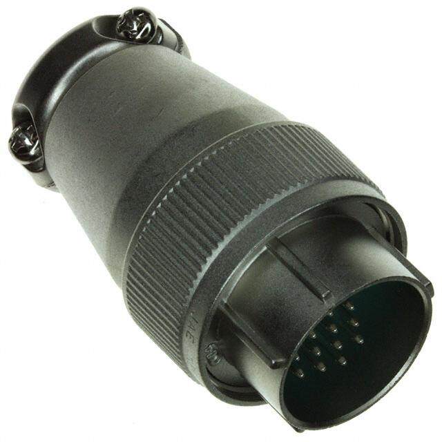
Cannon Audio XL XLR Plugs Female Plug XLR-*-11C Seepage13forassemblyinstructions Male Plug XLR-*-12C Seepage13forassemblyinstructions Receptacles Female Round Flange Receptacle XLR-*-13 Seepage15forpanelcutouts. SeePage22forlatchleverassembly/removalinsructions. Male Round Flange Receptacle XLR-*-14 Seepage15forpanelcutouts. Dimensionsshowninmm(inch) Specificationsanddimensionssubjecttochange www.ittcannon.com 9
Cannon Audio XL XLR Receptacles Female Rectangular Flange Receptacle XLR-*-31 Seepage15forpanelcutouts. Seepage22forlatchleverassembly/removalinstructions. Male Rectangular Flange Receptacle XLR-*-32 Seepage15forpanelcutouts. Female Rectangular Small Flange Receptacle XLR-*-31-F77 Seepage15forpanelcutouts. Seepage22forlatchleverassembly/removalinstructions. Male Rectangular Small Flange Receptacle XLR-*-32-F77 Seepage15forpanelcutouts. Dimensionsshowninmm(inch) Specificationsanddimensionssubjecttochange www.ittcannon.com 10
Cannon Audio XL XLR Receptacles and Bulkhead Adapters Male Rectangular Mini Flange Receptacle XLR- *-32-F512 Seepage15forpanelcutouts. Bulkhead Adapters Female-Female Bulkhead XLR-3-11-11-F Male-Male Bulkhead XLR-3-12-12-F Dimensionsshowninmm(inch) Specificationsanddimensionssubjecttochange www.ittcannon.com 11
Cannon Audio XL Dust Caps For use with Plastic Metallic (Brass) (Shell Styles) 11C 13 Female Cap 31 31-F77 XLR-SDC (M01) XLR-13RC 127007-0284 127007-0244 12C 14 Male Cap 32 32-F77 32-F512 XLR-PDC (M01) XLR-14PC 127007-0283 127007-0243 Small Bushing F502 012-4504-000 Note:Smallbushingisavailableseparately.Standardbushingissuppliedwithplug. Pin/Socket Insert Assembly XLR-3-Socket Insert Assembly XLR-3-Pin Insert Assembly 127007-0051 127007-0115 Contactfactoryforotherpinconfigurations. Dimensionsshowninmm(inch) Specificationsanddimensionssubjecttochange www.ittcannon.com 12
Cannon Audio XL XLR Assembly Instructions First, strip the wire to dimension, as shown. Insert bushing into shell. Slide shell assembly and insulator tube onto cable. Preparing Insert Assembly; Solder individual center conductors to each contact. Visually inspect solder joints before proceeding. Dimensionsshowninmm(inch) Specificationsanddimensionssubjecttochange www.ittcannon.com 13
Cannon Audio XL XLR Assembly Instructions Supporting the insert assembly in one hand, slide the insulator tube and shell assembly into position, as shown. Once assembled, fasten shell assembly with screw and washer. Please make sure to use washer with screw. Finally, screw clamp onto the shell assembly to lock cable into position. Please take extra precaution to orientate clamp into its proper position. The inside chamfer with the largest diameter must butt against the shell assembly. Perform a light pull test and visually inspect finished assembly. Dimensionsshowninmm(inch) Specificationsanddimensionssubjecttochange www.ittcannon.com 14
Cannon Audio XL XLR Panel Cutouts XLR-*-32 XLR-*-31 XLR-*-31/32-F77 XLR-*-32-F512 XLR-*-13 XLR-*-14 Dimensionsshowninmm(inch) Specificationsanddimensionssubjecttochange www.ittcannon.com 15
Cannon Audio XL XLM- Printed Circuit Board Series General Performance Characteristics ITT’s XLM male and female PCB metal flange mount receptacles offer durability, reliability, space savings and greatly improved EMI shielding over our plastic XLB-PCB connectors. Ease of installation is enhanced since the grounding terminal can be used to temporarily fasten the connector to the circuit board during assembly. The XLM- PCB connectors are interchangeable and intermateable with our XLR series. All XLM- PCB connectors are RoHS Compliant. Applications • Amplifiers • MedicalElectronics • IndustrialControlDevices • Equalizers • RecordingEquipment • Microphones • Mixers • TestInstruments • TVCameras Product Features and Benefits • PCB mount type with metal shell and barrel made as one piece • Nylon or PBT insulator (UL94V-O) • Improved EMI Shielding • Space saving (smaller flange) • Snap-in PCB retention feature • Separate ground contact • Quick disconnect latch lock • Interchangeable and Intermateable with XLR Series Performance Specifications TemperatureRating –35°Cto+85°C InsulationResistance 5,000MΩminat500VDC NumberofContacts 3 DurabilityCycles 500MatingCycles RatedCurrent 3A ContactResistance PCS:20mΩmax RatedVoltage(AC) 133V PCV:30mΩmax DielectricWithstandingVoltage(AC) 1,400V PCH:50mΩmax Materials and Finishes Description Material Finish/Treatment FemaleContacts CopperAlloy SilverorGold MaleContacts CopperAlloy SilverorGold Insulator NylonorPBT - Shell/Barrel ZincAlloy Nickel GroundingLug CopperAlloy Tin LatchLever Steel Nickel Dimensionsshowninmm(inch) Specificationsanddimensionssubjecttochange www.ittcannon.com 16
Cannon Audio XL XLM-PCB Part Number Selection Guide XLM 3 31 PCS ** F SERIES PREFIX CONTACTARRANGEMENTS SHELLSTYLES TERMINATIONFORPCB MODIFICATIONS SUFFIX CONNECTOR SERIES XLM MODIFICATIONS A176 -Goldplatedcontacts(for3pins) CONTACTARRANGEMENTS Seebelow3pinsonly SUFFIX “F” to identify lead free products SHELLSTYLE 31 - FemaleRectangularFlangeReceptacle XLMseries products are RoHScompliant 32 - MaleRectangularFlangeReceptacle TERMINATIONFORPCB PCS - StraightTermination PCV - Vertical90°Termination PCH-L- HorizontalLeftSideTermination(rearview) PCH-R-HorizontalRightSideTermination(rearview) Contact Configuration PCS PCV PCH Dimensionsshowninmm(inch) Specificationsanddimensionssubjecttochange www.ittcannon.com 17
Cannon Audio XL XLM-PCB Female Flange Receptacles StraightTermination XLM-3-31PCS-F Seepage27forpanelcutoutsandPCBLayouts. Seepage22forlatchleverassembly/removalinstructions. Vertical 90°Termination XLM-3-31-PCV-F Seepage27forpanelcutoutsandPCBLayouts. Seepage22forlatchleverassembly/removalinstructions. Horizontal Left SideTermination XLM-3-31PCH-L-F Seepage27forpanelcutoutsandPCBLayouts. Horizontal Right SideTermination Seepage22forlatchleverassembly/removalinstructions. XLM-3-31PCH-R-F Seepage27forpanelcutoutsandPCBLayouts. Seepage22forlatchleverassembly/removalinstructions. Note:SectionFreferencedonlinedrawingreferstopositionofflangefrontface. Dimensionsshowninmm(inch) Specificationsanddimensionssubjecttochange www.ittcannon.com 18
Cannon Audio XL XLM-PCB Male Flange Receptacles StraightTermination XLM-3-32PCS-F Vertical 90°Termination Seepage27forpanelcutoutsandPCBLayouts. XLM-3-32-PCV-F Seepage27forpanelcutoutsandPCBLayouts. Horizontal Left SideTermination XLM-3-32PCH-L-F Horizontal Right SideTermination Seepage27forpanelcutoutsandPCBLayouts. XLM-3-32PCH-R-F Note:SectionFreferencedonlinedrawingreferstopositionofflangefrontface. Seepage27forpanelcutoutsandPCBLayouts. Dimensionsshowninmm(inch) Specificationsanddimensionssubjecttochange www.ittcannon.com 19
Cannon Audio XL XLM-PCB Panel Cutouts Printed Circuit Board Hole Patterns (Ref.) Note:Seepage22forLatchLeverinstallationandremovalinstructions. Dimensionsshowninmm(inch) Specificationsanddimensionssubjecttochange www.ittcannon.com 20
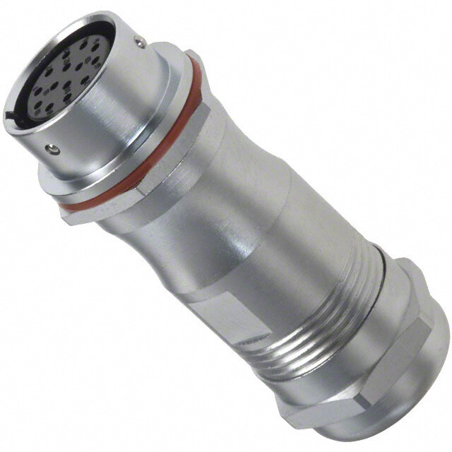
Cannon Audio XL Mini-XL General Performance Characteristics The world’s most sophisticated video, broadcast, and recording equipment require audio connector solutions with high reliability, unparallel performance, and robust durability. ITT Cannon is pleased to introduce the Mini-XL audio connector series. The Mini-XL connector is 4400%% ssmmaalllleerr than the industries standard XLR connector. Intended to meet the demands for high density compact audio applications, this quick one touch connect/disconnect circular connector is designed to withstand extreme field use. All Mini-XL connects are RoHS compliant. Applications • Amplifiers • MedicalElectronics • Industrial Control Devices • Equalizers • RecordingEquipment • Microphones • Mixers • TestInstruments • TV Cameras Product Features and Benefits • Rugged design to withstand extreme field use • Resilient socket insulator which minimizes vibration and electrical noise • Quick disconnect latch lock • Low reflectivity satin finish • 40% smaller than standard XLR • Ideal for high density applications • Contacts are gold plated Performance Specifications TemperatureRating –35°Cto+85°C InsulationResistance 5,000MΩminat500VDC NumberofContacts 3to6 DurabilityCycles 500MatingCycles RatedCurrent 3A ContactResistance 30mΩmax RatedVoltage(AC) 125V WireAccommodationReferenceAWG(Max)#24 DielectricWithstandingVoltage(AC) 250V WireCrossSelection(Max) 0.2mm Materials and Finishes Description Material Finish/Treatment Contacts CopperAlloy Gold Insulator PPS - Shell CopperAlloy Nickel Barrel CopperAlloy Nickel Bushing Thermo-plasticVulcanizates - LatchLever Steel Nickel Dimensions shown in mm (inch) Specifications and dimensions subject to change www.ittcannon.com 21
Cannon Audio XL Mini-XL Part Number Selection Guide M-XL 3 11 * SERIES PREFIX CONTACT ARRANGEMENTS SHELL STYLES CAP VARIATION CONNECTOR SERIES Mini-XL SHELL STYLE 11 - Female Plug 12 - Male Plug 14 - Male Round Flange Receptacle NUMBER OF CONTACTS See Below 3,4,5,6 31 - Female Rectangular Flange Receptacle CAP VARIATION S - Small Cap with Bushing (Standard) L - Large Cap M - Metal Cap Mini-XL series products are RoHS compliant Contact Configuration Number of Contacts 3 4 5 6 Contact Arrangements Wire AWG Max #24 #24 #24 #24 Wire Cross Section Max 0.2mm2 0.2mm2 0.2mm2 0.2mm2 Mini-XL connects are not intermatable with standard XLR, XLB-PCB, XLM-PCB connectors. Dimensions shown in mm (inch) Specifications and dimensions subject to change www.ittcannon.com 22
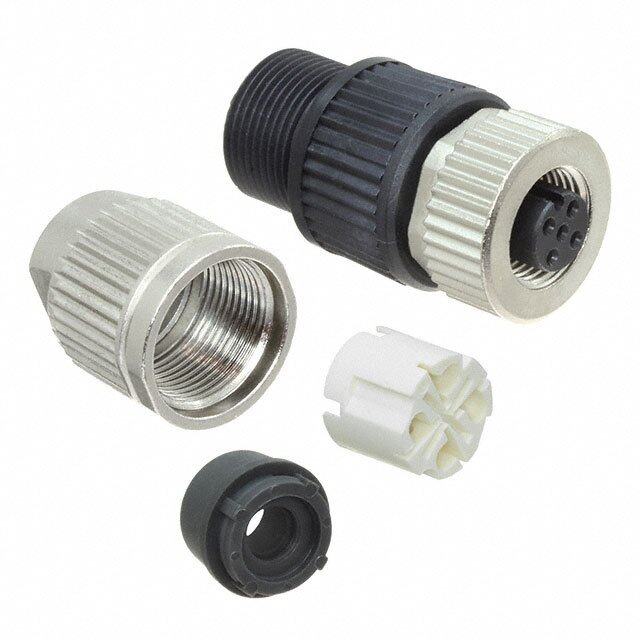
Cannon Audio XL Mini-XL Female Plug Small Cap with Bushing (Standard) M-XL- * - 11S See page 33 for assembly instructions Large Cap M-XL- * - 11L See page 33 for assembly instructions Metal Cap M-XL- * - 11M See page 33 for assembly instructions Dimensions shown in mm (inch) Specifications and dimensions subject to change www.ittcannon.com 23
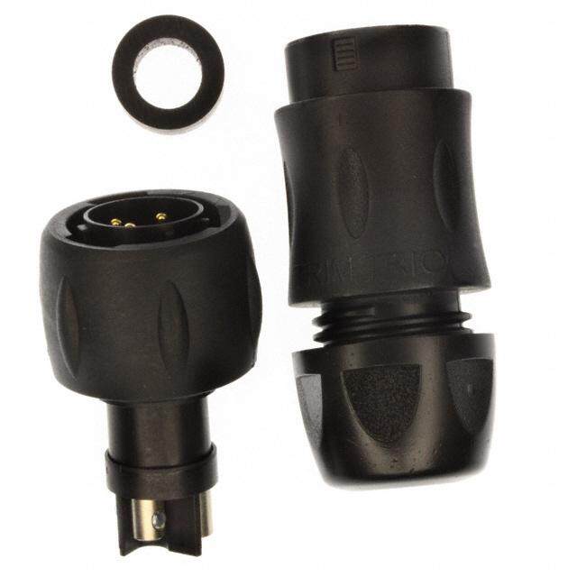
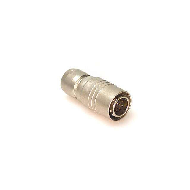
Cannon Audio XL Mini-XL Male Plug Small Cap with Bushing (Standard) M-XL- * - 12S See page 33 for assembly instructions Large Cap M-XL- * - 12L See page 33 for assembly instructions Metal Cap M-XL- * - 12M See page 33 for assembly instructions Dimensions shown in mm (inch) Specifications and dimensions subject to change www.ittcannon.com 24
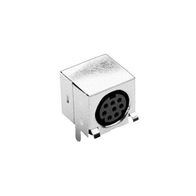
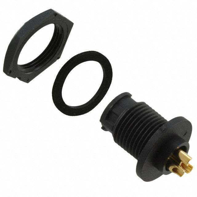
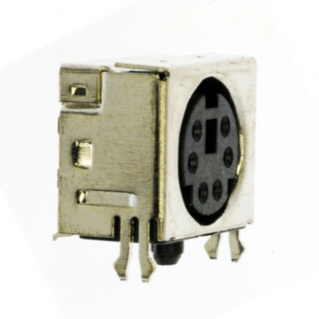
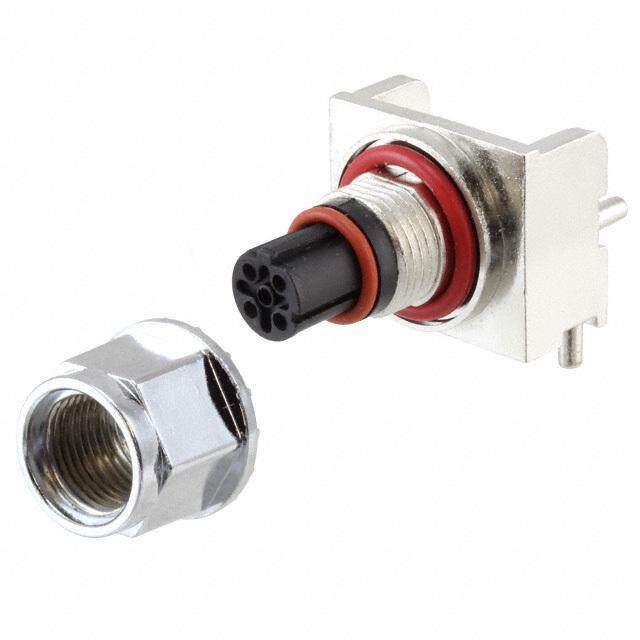
Cannon Audio XL Mini-XL Flange Receptacles Male Round Flange Receptacle M-XL- * - 14 See page 35 for panel cutouts. Female Rectangular Flange Receptacle M-XL- * - 31 See page 35 for panel cutouts. Note: Latch Lever is not removable. Dimensions shown in mm (inch) Specifications and dimensions subject to change www.ittcannon.com 25
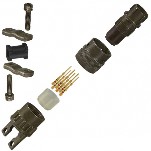
Cannon Audio XL Mini-XL Assembly Instructions Slide cap with bushing and cable strain relief onto cable, as shown. Strip wire to dimension shown. Preparing Insert Assembly; Solder individual center conductors to each contact. Visually inspect solder joints before proceeding. Supporting the insert assembly in one hand, slide cable strain relief into insert assembly. Please take extra precaution to orientate the two components together. Keying features has been added to ensure both components latch together properly. Crimp tabs located in rear of strain relief onto cable as shown. Dimensions shown in mm (inch) Specifications and dimensions subject to change www.ittcannon.com 26
Cannon Audio XL Mini-XL Assembly Instructions Insert complete sub-assembly into front barrel of connector. Please take extra precaution to orientate the barrel and sub-assembly during insertion. Keying feature has been added to ensure both components are posi- tioned properly during this step. Slide cap with bushing up to terminated connector housing. Note: Large and metal caps do not include bushing as shown. Rotate cap clockwise to thread onto connector housing to complete assem- bly. Perform a light pull test and visually inspect the finished assembly. Dimensions shown in mm (inch) Specifications and dimensions subject to change www.ittcannon.com 27
Cannon Audio XL Mini-XL Panel Cutouts Dimensions shown in inch (mm) Specifications and dimensions subject to change www.ittcannon.com 28
Cannon Audio XL Part Number Cross Reference ITT Part Part Number # of Package Description Configuration Page Number Designator GuideContacts Quantity 127008-0278 XLM-3-31PCH-L-F 3 XLM Female Flange Receptacle Horizontal Left Side Termination 25 25 127008-0280 XLM-3-31PCH-R-A176-F 3 XLM Female Flange Receptacle Horizontal Right Side Termination w/gold contacts 25 25 127008-0279 XLM-3-31PCH-R-F 3 XLM Female Flange Receptacle Horizontal Right Side Termination 25 25 127008-0275 XLM-3-31PCS-A176-F 3 XLM Female Flange Receptacle Straight Termination w/gold contacts 25 25 127008-0274 XLM-3-31PCS-F 3 XLM Female Flange Receptacle Straight Termination 25 25 127008-0277 XLM-3-31PCV-A176-F 3 XLM Female Flange Receptacle Vertical 90° Termination w/gold contacts 25 25 127008-0276 XLM-3-31PCV-F 3 XLM Female Flange Receptacle Vertical 90° Termination 25 25 127008-0286 XLM-3-32PCH-L-A176-F 3 XLM Male Flange Receptacle Horizontal Left Side Termination w/gold contacts 25 26 127008-0285 XLM-3-32PCH-L-F 3 XLM Male Flange Receptacle Horizontal Left Side Termination 25 26 127008-0288 XLM-3-32PCH-R-A176-F 3 XLM Male Flange Receptacle Horizontal Right Side Termination w/gold contacts 25 26 127008-0287 XLM-3-32PCH-R-F 3 XLM Male Flange Receptacle Horizontal Right Side Termination 25 26 127008-0282 XLM-3-32PCS-A176-F 3 XLM Male Flange Receptacle Straight Termination w/gold contacts 25 26 127008-0281 XLM-3-32PCS-F 3 XLM Male Flange Receptacle Straight Termination 25 26 127008-0284 XLM-3-32PCV-A176-F 3 XLM Male Flange Receptacle Vertical 90° Termination w/gold contacts 25 26 127008-0283 XLM-3-32PCV-F 3 XLM Male Flange Receptacle Vertical 90° Termination 25 26 127007-0244 XLR-13RC n/a XLR Metallic Female Dust Cap For use with shell sizes (11C,13,31,31-F77) 10 12 127007-0243 XLR-14PC n/a XLR Metallic Male Dust Cap For use with shell sizes (12C,14,32,32-F77,32-F512) 10 12 127007-0284 XLR-SDC (M01) n/a XLR Plastic Female Dust Cap For use with shell sizes (11C,13,31,31-F77) 10 12 127007-0283 XLR-PDC(M01) n/a XLR Plastic Male Dust Cap For use with shell sizes (12C,14,32,32-F77,32-F512) 10 12 012-4504-000 F502 n/a XLR Small Bushing Accessory Straight 100 12 127007-0128 XLR-2A-11C 2 XLR Female Plug Straight 10 9 127007-0136 XLR-2A-12C 2 XLR Male Plug Straight 10 9 127007-0124 XLR-2A-13 2 XLR Female Receptacle Round Flange w/latch 10 9 127007-0122 XLR-2A-14 2 XLR XLR Male Receptacle Round Flange w/latch 10 9 127007-0133 XLR-2A-31 2 XLR Female Receptacle Rectangular Flange w/latch 10 10 127007-0095 XLR-2A-31-F77 2 XLR Female Receptacle Rectangular Small Flange w/latch 10 10 127007-0155 XLR-2A-32 2 XLR Male Receptacle Rectangular Flange 10 10 127007-0111 XLR-2A-32-F512 2 XLR Male Receptacle Rectangular Mini-Flange 10 11 127007-0107 XLR-2A-32-F77 2 XLR Male Receptacle Rectangular Small Flange 10 10 www.ittcannon.com 29
Cannon Audio XL Part Number Cross Reference ITT Part Part Number # of Package Description Configuration Page Number Designator Guide Contacts Quantity 127007-0115 XLR-3 PIN INST ASSY 3 XLR Male Insert Assembly Straight 10 12 127007-0051 XLR-3 SKT INST ASSY 3 XLR Female Socket Insert Assembly Straight 10 12 127007-0366 XLR-3-11-11-F 3 XLR Female-Female Bulkhead Adapter Straight 10 11 127007-0058 XLR-3-11-C 3 XLR Female Plug Straight 10 9 127007-0214 XLR-3-11C-A176 3 XLR Female Plug Straight w/ gold contacts 10 9 127007-0367 XLR-3-12-12-F 3 XLR Male-Male Bulkhead Adapter Straight 10 11 127007-0103 XLR-3-12C 3 XLR Male Plug Straight 10 9 127007-0215 XLR-3-12C-A176 3 XLR Male Plug Straight w/ gold contacts 10 9 127007-0099 XLR-3-13 3 XLR Female Receptacle Round Flange w/latch 10 9 127007-0153 XLR-3-14 3 XLR Male Receptacle Round Flange w/latch 10 9 127007-0104 XLR-3-31 3 XLR Female Receptacle Rectangular Flange w/latch 10 10 127007-0211 XLR-3-31-A176 3 XLR Female Receptacle Rectangular Flange w/latch w/gold contacts 10 10 127007-0085 XLR-3-31-F77 3 XLR Female Receptacle Rectangular Small Flange w/latch 10 10 127007-0105 XLR-3-32 3 XLR Male Receptacle Rectangular Flange 10 10 127007-0212 XLR-3-32-A176 3 XLR Male Receptacle Rectangular Flange w/gold contacts 10 10 127007-0040 XLR-3-32-F512 3 XLR Male Receptacle Rectangular Mini-Flange 10 11 127007-0086 XLR-3-32-F77 3 XLR Male Receptacle Rectangular Small Flange 10 10 127007-0282 XLR-3-A176 PIN INST ASSY 3 XLR Male Insert Assembly Straight w/gold contacts 10 12 127007-0194 XLR-4 SKT INST ASSY 4 XLR Female Socket Insert Assembly Straight 10 * 127007-0087 XLR-4-11C 4 XLR Female Plug Straight 10 9 127007-0065 XLR-4-12C 4 XLR Male Plug Straight 10 9 127007-0348 XLR-4-12C-A176 4 XLR Male Plug Straight w/gold contacts 10 9 127007-0125 XLR-4-13 4 XLR Female Receptacle Round Flange w/latch 10 9 127007-0168 XLR-4-14 4 XLR Male Receptacle Round Flange w/latch 10 9 127007-0100 XLR-4-31 4 XLR Female Receptacle Rectangular Flange w/latch 10 10 127007-0210 XLR-4-31-A176 4 XLR Female Receptacle Rectangular Flange w/latch w/gold contacts 10 10 127007-0064 XLR-4-31-F77 4 XLR Female Receptacle Rectangular Small Flange w/latch 10 10 127007-0101 XLR-4-32 4 XLR Male Receptacle Rectangular Flange 10 10 127007-0204 XLR-4-32-F512 4 XLR Male Receptacle Rectangular Mini-Flange 10 11 127007-0102 XLR-4-32-F77 4 XLR Male Receptacle Rectangular Small Flange 10 10 127007-0195 XLR-5-SKT INST ASSY 5 XLR Female Insert Straight 10 n/a 127007-0129 XLR-5-11C 5 XLR Female Plug Straight 10 9 127007-0052 XLR-5-12C 5 XLR Male Plug Straight 10 9 127007-0202 XLR-5-13 5 XLR Female Receptacle Round Flange w/latch 10 9 127007-0169 XLR-5-14 5 XLR Male Receptacle Round Flange w/latch 10 9 127007-0134 XLR-5-31 5 XLR Female Receptacle Rectangular Flange w/latch 10 10 127007-0053 XLR-5-31-F77 5 XLR Female Receptacle Rectangular Small Flange w/latch 10 10 127007-0156 XLR-5-32 5 XLR Male Receptacle Rectangular Flange 10 10 *Contact Factory for drawings www.ittcannon.com 30
Cannon Audio XL Part Number Cross Reference ITT Part Part Number # of Package Description Configuration Page Number Designator GuideContacts Quantity 127007-0127 XLR-5-32-F512 5 XLR Male Receptacle Rectangular Mini-Flange 10 11 127007-0106 XLR-5-32-F77 5 XLR Male Receptacle Rectangular Small Flange 10 10 127007-0130 XLR-6-11C 6 XLR Female Plug Straight 10 9 127007-0137 XLR-6-12C 6 XLR Male Plug Straight 10 9 127007-0201 XLR-6-13 6 XLR Female Receptacle Round Flange w/latch 10 9 127007-0170 XLR-6-14 6 XLR Male Receptacle Round Flange w/latch 10 9 127007-0163 XLR-6-31 6 XLR Female Receptacle Rectangular Flange w/latch 10 10 127007-0092 XLR-6-31-F77 6 XLR Female Receptacle Rectangular Small Flange w/latch 10 10 127007-0157 XLR-6-32 6 XLR Male Receptacle Rectangular Flange 10 10 127007-0206 XLR-6-32-F512 6 XLR Male Receptacle Rectangular Mini-Flange 10 11 127007-0164 XLR-6-32-F77 6 XLR Male Receptacle Rectangular Small Flange 10 10 127007-0131 XLR-6A-11C 6 XLR Female Plug Straight 10 9 127007-0138 XLR-6A-12C 6 XLR Male Plug Straight 10 9 127007-0198 XLR-6A-13 6 XLR Female Receptacle Round Flange w/latch 10 9 127007-0171 XLR-6A-14 6 XLR Male Receptacle Round Flange w/latch 10 9 127007-0176 XLR-6A-31 6 XLR Female Receptacle Rectangular Flange w/latch 10 10 127007-0342 XLR-6A-31-A176 6 XLR Female Receptacle Rectangular Flange w/latch w/gold contacts 10 10 127007-0094 XLR-6A-31-F77 6 XLR Female Receptacle Rectangular Small Flange w/latch 10 10 127007-0159 XLR-6A-32 6 XLR Male Receptacle Rectangular Flange 10 10 127007-0205 XLR-6A-32-F512 6 XLR Male Receptacle Rectangular Mini-Flange 10 11 127007-0197 XLR-6A-32-F77 6 XLR Male Receptacle Rectangular Small Flange 10 10 127007-0123 XLR-7-11C 7 XLR Female Plug Straight w/gold contacts 10 9 127007-0097 XLR-7-12C 7 XLR Male Plug Straight w/gold contacts 10 9 127007-0166 XLR-7-13 7 XLR Female Receptacle Round Flange w/latch w/gold contacts 10 9 127007-0132 XLR-7-14 7 XLR Male Receptacle Round Flange w/latch w/gold contacts 10 9 127007-0135 XLR-7-31 7 XLR Female Receptacle Rectangular Flange w/latch w/gold contacts 10 10 127007-0096 XLR-7-31-F77 7 XLR Female Receptacle Rectangular Small Flange w/latch w/gold contacts 10 10 127007-0158 XLR-7-32 7 XLR Male Receptacle Rectangular Flange w/gold contacts 10 10 127007-0112 XLR-7-32-F512 7 XLR Male Receptacle Rectangular Mini-Flange w/gold contacts 10 11 127007-0165 XLR-7-32-F77 7 XLR Male Receptacle Rectangular Small Flange w/gold contacts 10 10 127010-0003 M-XL-3-11S 3 Mini-XL Female Plug w/small cap and bushing Straight 50 30 127010-0007 M-XL-3-11L 3 Mini-XL Female Plug w/large cap Straight 50 30 127010-0011 M-XL-3-11M 3 Mini-XL Female Plug w/metal cap Straight 50 30 127010-0015 M-XL-3-12S 3 Mini-XL Male Plug w/small cap and bushing Straight 50 31 127010-0019 M-XL-3-12L 3 Mini-XL Male Plug w/large cap Straight 50 31 127010-0023 M-XL-3-12M 3 Mini-XL Male Plug w/metal cap Straight 50 31 127010-0027 M-XL-3-14 3 Mini-XL Male Receptacle Round Flange 50 32 127010-0031 M-XL-3-31 3 Mini-XL Female Receptacle Rectangular Flange w/latch 50 32 127010-0004 M-XL-4-11S 4 Mini-XL Female Plug w/small cap and bushing Straight 50 30 127010-0008 M-XL-4-11L 4 Mini-XL Female Plug w/large cap Straight 50 30 127010-0012 M-XL-4-11M 4 Mini-XL Female Plug w/metal cap Straight 50 30 www.ittcannon.com 31
Cannon Audio XL Part Number Cross Reference ITT Part Part Number # of Package Description Configuration Page Number Designator Guide Contacts Quantity 127010-0016 M-XL-4-12S 4 Mini-XL Male Plug w/small cap and bushing Straight 50 31 127010-0020 M-XL-4-12L 4 Mini-XL Male Plug w/large cap Straight 50 31 127010-0024 M-XL-4-12M 4 Mini-XL Male Plug w/metal cap Straight 50 31 127010-0028 M-XL-4-14 4 Mini-XL Male Receptacle Round Flange 100 32 127010-0032 M-XL-4-31 4 Mini-XL Female Receptacle Rectangular Flange w/latch 50 32 127010-0005 M-XL-5-11S 5 Mini-XL Female Plug w/small cap and bushing Straight 50 30 127010-0009 M-XL-5-11L 5 Mini-XL Female Plug w/large cap Straight 50 30 127010-0013 M-XL-5-11M 5 Mini-XL Female Plug w/metal cap Straight 50 30 127010-0017 M-XL-5-12S 5 Mini-XL Male Plug w/small cap and bushing Straight 50 31 127010-0021 M-XL-5-12L 5 Mini-XL Male Plug w/large cap Straight 50 31 127010-0025 M-XL-5-12M 5 Mini-XL Male Plug w/metal cap Straight 50 31 127010-0029 M-XL-5-14 5 Mini-XL Male Receptacle Round Flange 100 32 127010-0033 M-XL-5-31 5 Mini-XL Female Receptacle Rectangular Flange w/latch 50 32 127010-0006 M-XL-6-11S 6 Mini-XL Female Plug w/small cap and bushing Straight 50 30 127010-0010 M-XL-6-11L 6 Mini-XL Female Plug w/large cap Straight 50 30 127010-0014 M-XL-6-11M 6 Mini-XL Female Plug w/metal cap Straight 50 30 127010-0018 M-XL-6-12S 6 Mini-XL Male Plug w/small cap and bushing Straight 50 31 127010-0022 M-XL-6-12L 6 Mini-XL Male Plug w/large cap Straight 50 31 127010-0026 M-XL-6-12M 6 Mini-XL Male Plug w/metal cap Straight 50 31 127010-0030 M-XL-6-14 6 Mini-XL Male Receptacle Round Flange 100 32 127010-0034 M-XL-6-31 6 Mini-XL Female Receptacle Rectangular Flange w/latch 50 32 www.ittcannon.com 32
Cannon Audio XL Glossary of Terms AAMMPP:: (Ampere) Unit of electrical current. IInnssuullaattiioonn RReessiissttaannccee:: The electrical resistance between two conductors separated by an insulating medium. AAmmpplliiffiieerr:: A device which increases the amplitude of a signal. MMiinnii--XXLL:: Similar to XLR series but 40% smaller in size, configu- AAWWGG:: (American Wiring Gauge) A U.S. measurement stan- rations available from 3 to 6 pins. dard of the diameter of non-ferrous wire, which includes cop- per and aluminum. As a AWG number increases the diameter MMiixxeerr:: A device which accepts two or more audio inputs and of the wire decreases. provides one or more audio outputs. BBaallaanncceedd AAuuddiioo:: A type of audio signal which uses two OOppeerraattiinngg TTeemmppeerraattuurree:: Range of temperature in which out- inverted voltages as a way to prevent unwanted noise being put frequency and other electrical and environmental characteris- picked up by cables. tics meet connector specifications. BBuuss:: The pathway along which an electrical signal flows. For PPeeaakk:: The highest level of strength of an audio signal. Often example, the output of a sound mixer is referred to as the refers to an unacceptably high level, where the signal begins dis- master stereo bus. torting. CChhaannnneell:: Similar to a bus, a pathway through an audio PPhhaannttoomm PPoowweerr:: A DC current which is sent through audio device. For example, sound mixers have multiple input chan- cables to provide power for devices such as microphones. nels. PPlluugg:: One half of a mating pair of connectors. The plug inter- CCoonnnneeccttoorr DDuurraabbiilliittyy:: The number of times a connector face normally goes outside the jack interface. can be physically mated and still maintain its specified performance. RRaatteedd VVoollttaaggee:: Maximum voltage that a type of wire, plug, socket or circuit breaker is designed for. CCoonnttaacctt RReessiissttaannccee:: The measurement of the DC electrical resistance between a pair of mated contacts. Usually specified RReecceeppttaaccllee: A term used to describe a connector assembly usu- as being measured after a given number of mating cycles. ally bulkhead or PCB mounted. DDeecciibbeell ((ddBB)):: Logarithmic measurement of signal strength. SStteerreeoo:: Audio which is made up of two channels — left and 1/10 of a Bel. right. DDiieelleeccttrriicc WWiitthhssttaannddiinngg VVoollttaaggee ((AACC)):: The maximum TToonnee:: An audio test signal used to adjust levels, test signal qual- voltage that a dielectric material can withstand without failure. ity, identify signal pathways, etc. DDuusstt CCaapp:: A mechanical device attached to the mating face TTrraannssdduucceerr: Any device which converts energy from one form of an unmated connector to prevent ingress of contaminant's into another. Microphones and loudspeakers are both transduc- and provide protection against mechanical damage. ers. EEqquuaalliizzaattiioonn:: The process of adjusting various audio fre- VVoolluummee UUnniitt ((VVUU)):: a unit used to measure the volume of an quencies to correct or enhance the sound. audio signal. FFrreeqquueennccyy RReessppoonnssee:: The sensitivity of an audio device to WWaavveelleennggtthh:: The length of a wave, measured from any point various frequencies, i.e. the amount each frequency is boosted, on a wave to the corresponding point on the next phase of the attenuated or reproduced. wave. GGaaiinn:: The amplification level of an audio signal. XXLLBB--PPCCBB:: A lockable printed circuit board receptacle, available with 3 pins. XLB "X series", “L latch” and “B board mount plastic HHeerrttzz:: Unit of frequency, cycles per second. pcb shell”. HHeeaaddrroooomm:: In a cable or audio device, the difference XXLLMM--PPCCBB:: A lockable printed circuit board receptacle, available between the maximum level of the signal being carried and the with 3 pins. XLM "X series", “L latch” and “M metal pcb shell”. maximum level the device is capable of carrying without distor- tion. XXLLRR:: A lockable connector, configurations available from 2 to 7 pins. The most common XLR in audio products is the 3-pin XLR. IImmppeeddaannccee: The amount of opposition a device has to an Our original design was the "X series", which later incorporated a audio signal. In technical terms, the combined effect of capaci- latch (L) and then rubber insulation (R), leading to the acronym tance, inductance, and resistance on a signal. "XLR". www.ittcannon.com 33
Cannon Audio XL 1. MATERIAL CONTENT AND PHYSICAL 4. DISPOSAL Product Warranty FORM Incineration of certain materials may release A limited warranty applies to Cannon prod- Electrical connectors do not usually contain noxious or even toxic fumes. ucts. In general, except for obligations hazardous materials. They contain conduct- assumed by Cannon under this warranty, ing and non-conducting materials and can 5. APPLICATION Cannon shall not be liable for any loss, dam- be divided into two groups. Connectors with exposed contacts should age, cost of repairs, incidental or consequen- a) Printed circuit types and low cost audio not be selected for use on the current supply tial damages of any kind, whether or not types which employ all plastic insulators and side of an electrical circuit, because an elec- based on express or implied warranty, con- casings. tric shock could result from touching tract, negligence or strict liability arising in b) Rugged, Fire Barrier and High Reliability exposed contacts on an unmated connector. connection with the design, manufacture, types with metal casings and either natural Voltages in excess of 30 V ac or 42.5 V dc are sale, use or repair of the products. Product rubber, synthetic rubber, plastic or glass potentially hazardous and care should be availability, prices and delivery dates are insulating materials. Contact materials vary taken to ensure that such voltages cannot be exclusively subject to our respective order with type of connector and also application transmitted in any way to exposed metal confirmation form; the same applies to and are usually manufactured from either: parts of the connector body. The connector orders based on development samples deliv- Copper, copper alloys, nickel, alumel, and wiring should be checked, before mak- ered. Please refer to www.ittcannon.com chromel or steel. In special applications, ing live, to have no damage to metal parts or (General Terms of Sale) for the complete text other alloys may be specified. insulators, no solder blobs, loose strands, of Cannon’s applicable Terms and conducting lubricants, swarf, or any other Conditions, including Warranty. 2. FIRE CHARACTERISTICS AND ELECTRIC undesired conducting particles. Circuit SHOCK HAZARD resistance and continuity check should be This publication is not to be construed as an There is no fire hazard when the connec- made to make certain that there are no high offer. It is intended merely as an invitation to tor is correctly wired and used within the resistance joints or spurious conducting make an offer. By this publication, Cannon specified parameters. Incorrect wiring or paths. Always use the correct application does not assume responsibility or any liabili- assembly of the connector or careless use tools as specified in the Data Sheet/Catalog. ty for any patent infringements or other of metal tools or conductive fluids, or Do not permit untrained personnel to wire, rights of third parties which may result from transit damage to any of the component assemble or tamper with connectors. For its use. parts may cause electric shock or burns. operation voltage please see appropriate Live circuits must not be broken by sepa- national regulations. rating mated connectors as this may Reprinting this publication is generally per- cause arcing, ionization and burning.Heat IMPORTANT GENERAL INFORMATION mitted, indicating the source. However, dissipation is greater at maximum resistance (i) Air and creepage paths/Operating volt- Cannon's prior consent must be obtained in in a circuit. Hot spots may occur when resist- age. The admissible operating voltages all cases. “Engineered for life” is a registered ance is raised locally by damage, e.g. cracked depend on the individual applications and trademark of ITT Corporation ©2006. All or deformed contacts, broken strands of the valid national and other applicable safe- other trademarks or registered trademarks wire. Local overheating may also result from ty regulations. are property of their respective owners. All the use of the incorrect application tools or For this reason the air and creepage path data subject to change without notice. from poor quality soldering or slack screw data are only reference values. Observe terminals. Overheating may occur if the rat- reduction of air and creepage paths due to ings in the product Data Sheet/Catalog are PC board and/or harnessing. exceeded and can cause breakdown of insu- This document does not contain technical lation and hence electric shock. If heating is (ii) Temperature data whose export is restricted by the Arms allowed to continue it intensifies by further All information given are temperature limits. Export Control Act (Title 22, U.S.C., App increasing the local resistance through loss The operation temperature depends on the 2401 et. Seq.) of temper of spring contacts, formation of individual application. oxide film on contacts and wires and leakage currents through carbonization of insulation (iii) Other important information and tracking paths. Fire can then result in Cannon continuously endeavors to improve the presence of combustible materials and their products. Therefore, Cannon products this may release noxious fumes. Overheating may deviate from the description, technical may not be visually apparent. Burns may data and shape as shown in this catalog and result from touching overheated compo- data sheets. nents. 3. HANDLING ITT Interconnect Solutions, a Division of ITT Care must be taken to avoid damage Corporation manufactures the highest qual- to any component parts of electrical connec- ity products available in the marketplace; tors during installation and use. Although however these products are intended to be there are normally no sharp edges, care used in accordance with the specifications in must be taken when handling certain com- this publication. Any use or application that ponents to avoid injury to fingers. Electrical deviates from the stated operating specifica- connectors may be damaged in transit to the tions is not recommended and may be customers, and damage may result in cre- unsafe. No information and data contained ation of hazards. Products should therefore in this publication shall be construed to cre- be examined prior to installation/use and ate any liability on the part of Cannon. Any rejected if found to be damaged. new issue of this publication shall automati- cally invalidate and supersede any and all previous issues. www.ittcannon.com 34
Customer Support Locations CHINA Tuopandun Industrial Area, Jinda Cheng, Xiner Village, Shajing Town, Baoan District, Shenzhen City, Guangdong, China 518125 Phone: +86.755.2726.7238 Fax: +86.755.2726.7515 GERMANY Cannonstrasse 1 Weinstadt, 71384 phone: +49.7151.699.0 fax: +49.7151.699.217 HONG KONG Units 2405-6, 24/F, ING Tower 308 Des Voeux Road Central Hong Kong phone: +852.2732.2720 fax: +852.2732.2919 ITALY Corso Europa 41/43 Lainate (MI), Italy 20020 phone: +39.02938721 fax: +39.0293872300 JAPAN 11-3, 5 Chome, Hibarigaoka, Zama-shi Kanagawa, Japan 228-0003 phone: +81.462.57.2010 fax: + 82.462.57.1680 UK Jays Close, Viables Estate Basingstoke, RG22 4BA phone: +44.1256.311200 fax: +44.1256.323356 USA 56 Technology Dr. Irvine, CA 92618 toll free: 1.800.854.3028 phone: 1.714.557.4700 fax: 1.714.628.2142 ©2017 ITT Inc. “Engineered for life” and “Cannon” are registered trademarks of ITT Inc. Specification and other data are based on information available at the time of printing, and are subject to change without notice. www.ittcannon.com Audio XL 20170721.