ICGOO在线商城 > 电源 - 外部/内部(外接) > AC DC 转换器 > LXN1701-6G
 Datasheet下载
- 型号: LXN1701-6G
- 制造商: Power-One
- 库位|库存: xxxx|xxxx
- 要求:
| 数量阶梯 | 香港交货 | 国内含税 |
| +xxxx | $xxxx | ¥xxxx |
查看当月历史价格
查看今年历史价格
LXN1701-6G产品简介:
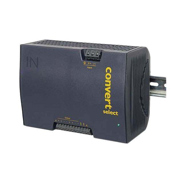
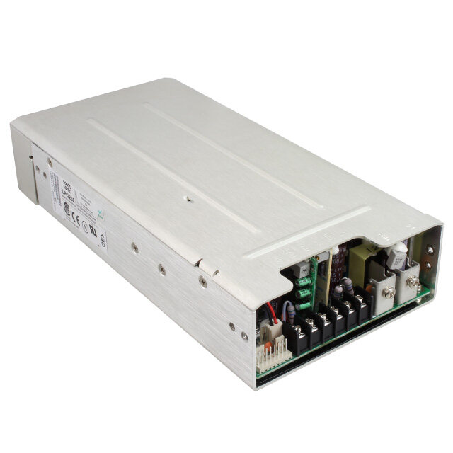
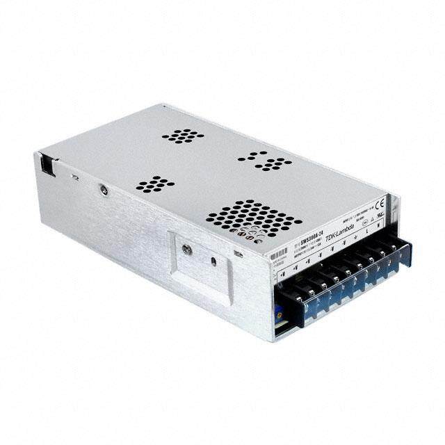
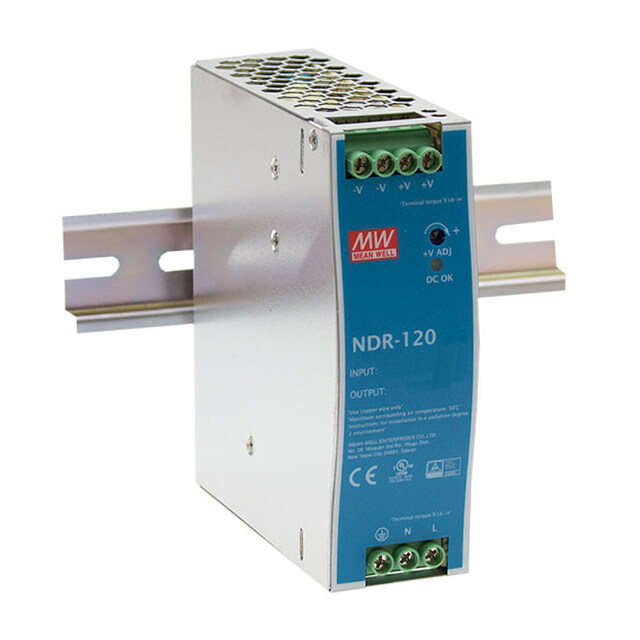
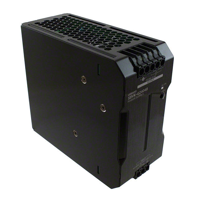
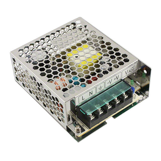
ICGOO电子元器件商城为您提供LXN1701-6G由Power-One设计生产,在icgoo商城现货销售,并且可以通过原厂、代理商等渠道进行代购。 LXN1701-6G价格参考。Power-OneLXN1701-6G封装/规格:AC DC 转换器, 封闭式,保形涂层 AC DC 转换器 1 输出 37V 13.4A 85 ~ 264 VAC 输入。您可以下载LXN1701-6G参考资料、Datasheet数据手册功能说明书,资料中有LXN1701-6G 详细功能的应用电路图电压和使用方法及教程。
| 参数 | 数值 |
| 产品目录 | |
| 描述 | AC/DC CONVERTER 37V 500W |
| 产品分类 | |
| 品牌 | Bel Power Solutions |
| 数据手册 | |
| 产品图片 |
|
| 产品型号 | LXN1701-6G |
| rohs | 无铅 / 符合限制有害物质指令(RoHS)规范要求 |
| 产品系列 | X |
| 其它名称 | 179-2486 |
| 功率(W) | 500W |
| 功率(W)-最大值 | 496W |
| 大小/尺寸 | 7.64" 长 x 4.47" 宽 x 5.43" 高 (194.0mm x 106.6mm x 138.0mm) |
| 安装类型 | DIN 轨道 |
| 工作温度 | -40°C ~ 60°C |
| 应用 | ITE(商业) |
| 所需最小负载 | - |
| 效率 | 87% |
| 标准包装 | 5 |
| 特性 | 可调输出,负载均分,PFC,通用输入 |
| 特色产品 | http://www.digikey.cn/product-highlights/cn/zh/power-one-x-series-din-rail-power-supplies/3497 |
| 电压-输入 | 85 ~ 264 VAC |
| 电压-输出1 | 37V |
| 电压-输出2 | - |
| 电压-输出3 | - |
| 电压-输出4 | - |
| 电压-隔离 | 2.8kV(2800V) |
| 电流-输出(最大值) | 13.4A |
| 相关产品 | /product-detail/zh/UMB-W/179-2443-ND/3609360 |
| 类型 | 封闭式 |
| 认可 | cCSAus, CE |
| 输出数 | 1 |


PDF Datasheet 数据手册内容提取
X Series Data Sheet 375, 500 Watt AC-DC and DC-DC DIN-Rail Converters 375, 500 Watt AC-DC (DC-DC) Converters Convert Select Features • RoHS lead-free-solder and lead-solder-exempted products are available (cid:127) Rugged 35 mm DIN-rail snap-fit design (cid:127) Class I equipment (cid:127) Universal AC-input with single stage conversion AC-DC or DC-DC, input 100–240 VAC or 90–350 VDC (cid:127) Power factor correction, harmonics IEC/EN 61000-3-2 (cid:127) Virtually no inrush current (cid:127) Immunity to IEC/EN 61000-4-2, -3, -4, -5, -6, -8, -11 (cid:127) Emissions according to EN 55011/55033 (cid:127) Very high efficiency; up to 89% (cid:127) Short-term output peak power capability, rectangular current limiting characteristic (cid:127) Single or two independently regulated outputs with 24, 36, or 48 V (cid:127) Outputs no-load, overload, and short-circuit proof (cid:127) PCBs protected by lacquer (cid:127) Very high reliability 138 5.43" Safety according to IEC/EN 50178, IEC 61010-1, IEC 194 60950-1, UL/CSA 60950-1 2nd Ed. 7.64" 114 4.49" Description The Convert Select front end series represents a family of current, high immunity to transients and surges, and low DIN-rail mountable DC-DC and AC-DC converters with power electromagnetic emissions. Internal protection circuits such as factor correction. The converters have been designed input over- and undervoltage lockout, thermal protection, as according to the latest industry requirements and standards. well as output overvoltage protection by a second control loop They are ideal for use in outdoor and other demanding ensure safe operation of the final system. applications to power building control systems, factory The outputs deliver an electrically-isolated Safety Extra Low automation, industrial controls, instrumentation, electro- Voltage, SELV, (except models LXR/LXN1740) and low output magnetic drives, fans, and other DC loads. Different models noise. They are no-load, overload, and short-circuit proof. The are available with a single output or two independently electronically controlled short-term peak power capability of up regulated, electrically isolated outputs with 24, 36, or 48 V. to 150% of the rated output power enables the front end Special models for battery charging are available. converters to deliver additional power to start-up motors or to Key features of the Convert Select line include power factor safely operate subsequent circuit breakers. Built-in large sized correction with low harmonic distortion, negligibly low inrush output capacitors absorb possible reverse energy, which may Table of Contents Page Page Description............................................................................1 Immunity to Environmental Conditions...............................13 Model Selection ....................................................................2 Mechanical Data.................................................................14 Functional Description..........................................................4 Safety and Installation Instructions.....................................15 Electrical Input Data..............................................................5 Description of Options ........................................................17 Electrical Output Data...........................................................7 Accessories.........................................................................20 Electromagnetic Compatibility (EMC).................................12 Copyright © 2017, Bel Power Solutions Inc. All rights reserved. MELCHER BCD20021-G Rev AE, 12-Oct-2017 The Power Partners. Page 1 of 21
X Series Data Sheet 375, 500 Watt AC-DC and DC-DC DIN-Rail Converters be caused by quick deceleration of electromagnetic drives The thermal concept allows operation at full load up to an connected directly to the output. A green LED at the front cover ambient temperature of 60 °C in free air without forced cooling. displays the status of the output(s). A rugged DIN snap-fit device allows easy and reliable fixing onto the various 35 mm DIN-rail models. The converters are The Convert Select Series was designed according to all fitted with cage clamp terminals easily accessible from the relevant international safety standards. The converters are front. System connectors with screw terminals for use with pre- approved by TÜV and UL, and are UL 508 listed. Adequate assembled harnesses, external adjustment of the output clearances and creepage distances allow operation in voltage, as well as various auxiliary functions are available as pollution degree 3 environment (with AC input). All board options. assemblies are coated with a protective lacquer. Model Selection Table 1: Standard models Output 1 Output 2 Output Power Operating Input Type Effic. Options3, 5 V 1 I V 1 I P Voltage Designation ηηηηη 7 o1 nom o1 nom o2 nom o2 nom o nom min [VDC] [A] [VDC] [A] [W] V - V [%] i min i max 24.7 15 - - 371 85 2 – 264 VAC, LXR1601-6G 87 R 47 – 63 Hz 4, D1, D2, D5 24.7 20 - - 494 LXN1601-6G 87 902 –350 VDC 6 M1, M2 37 10 - - 370 LXR1701-6G 3 88 F, K2 37 13.4 - - 496 LXN1701-6G 3 88 non-G 49.4 7.5 - - 371 LXR1801-6G 88 49.4 10 - - 494 LXN1801-6G 88 24.7 10 24.7 10 494 LXN2660-6G 87 37 6.7 37 6.7 496 LXN2770-6G 3 88 49.4 5 49.4 5 494 LXN2880-6G 88 1 R-input not connected. 2 For derating at low input voltage see section Output Power Derating. 3 For minimum quantity and lead times contact Power-One. 4 The converters have been tested up to 440 Hz; for operating frequencies <47 Hz or >63 Hz contact Power-One. 5 On double-output models the options R, M2, D1, D2, D5 are related to the 2nd output only. 6 V ≤ 250 VDC for models with option F i 7 Min. efficiency at V , I , and T = 25 °C. Typical values are approx. 2% better. i nom o nom A Table 2: Battery charger models (M1 included) Output Voltage Nominal Output Values Operating Input Type Designation Effic. Options 3 V V 1 V V 5 I 5 P 5 Voltage ηηηηη 7 Bat o safe o max o nom o nom o nom min [VDC] [VDC] [VDC] [VDC] [A] [W] V - V [%] i min i max 24 25.681 29.3 27.3 12.6 344 85 2 – 264 VAC, LXR1240-6M1G 87 F, K2, 47 – 63 Hz 4, non-G 16.8 458 LXN1240-6M1G 87 902 – 350 VDC 6 36 38.521 43.95 40.88 8.4 343 LXR1840-6M1G 3 87 11.2 458 LXN1840-6M1G3 87 48 51.361 58.6 54.5 6.3 343 LXR1740-6M1G 87 8.4 458 LXN1740-6M1G 87 1 Setting voltage (typ.) with open R-input 2 For derating at low input voltage see section Output Power Derating. 3 For minimum quantity and lead times consult the factory. 4 The converters have been tested up to 440 Hz; for operating frequency <47 Hz or >63 Hz contact the factory 5 Nominal output figures, calculated with a cell voltage of 2.27 V at 20 °C. 6 V ≤ 250 VDC for models with option F. i 7 Min. efficiency at V , V , I , and T = 25 °C. Typical values are approx. 2% better. i nom o nom o nom A NFND: Not for new designs. Preferred for new designs MELCHER BCD20021-G Rev AE, 12-Oct-2017 The Power Partners. Page 2 of 21
X Series Data Sheet 375, 500 Watt AC-DC and DC-DC DIN-Rail Converters Part Number Description L X N 2 660 -6 D2 F K2 G Input voltage range..........................................................................L Series............................................................................................. X Nominal output power 375W..........................................................................R 500 W......................................................................... N Number of outputs.......................................................................1, 2 Type specification..............................................................000 – 999 Operational ambient temperature range T A –40 to 60 °C...............................................................-6 Customer-specific..................................................-0, -5 Options Output voltage control input 2.......................................................R Save data signal 2..........................................................D1, D2, D5 Multiple functions via D-SUB connector 1..................M1, M2 Built-in second fuse, input diode.................................F System connector......................................................K2 RoHS compliant for all six substances.......................G 1 Only one of these options is possible. Note: The sequence of options must follow the order above. NFND: Not for new designs. Preferred for new designs Example: LXN2660-6D2FK2G: Power factor corrected AC-DC converter, operating input voltage range 85 – 264 VAC, 2 electrically isolated and individually regulated outputs, each providing 24.7 V, 10 A, options D2, F, K2, and RoHS- compatible for all 6 substances. Product Marking Basic type designation, applicable safety approval and recognition marks, CE mark, warnings, pin designation, Company logo. Specific type designation, input voltage range, nominal output voltages and currents, degree of protection, batch and serial number, data code including production site, version, date of production. MELCHER BCD20021-G Rev AE, 12-Oct-2017 The Power Partners. Page 3 of 21
X Series Data Sheet 375, 500 Watt AC-DC and DC-DC DIN-Rail Converters 130 kHz. The power-factor-corrected single-step conversion of Functional Description the input voltage to a low output voltage results in extremely The X Series converters are primary controlled AC-DC or DC- high efficiency. Depending on the output power, the converters DC flyback converters with a constant switching frequency of are fitted with three (375 W) or four (500 W) powertrains. 03105 Fuse L 3 C 2 Vo+ C Y y 3 er er er Input filt Rectifier Input filt Shunt Shunt Output filt 67 N 2 C 4 Vo– 2nd fuse Cy Cy Y 5 (option F) 8 9 1 Control circuit Vo/Io control including 1 PFC and 12 input OVP/UVP 2nd control loop (SELV) 10 Aux1 11 Aux2 Fig. 1 LXR 375 W single-output converter. 03106 Fuse L 3 Input filter Rectifier Cy Input filter Shunt Shunt + Output filter Cy 23 Vo+ N 22nd fuse Cy Cy Cy 45 Vo– (option F) 1 Control circuit V /I control o o including PFC and 2nd control loop (SELV) input OVP/UVP ut filter + put filter Cy 67 Vo+ Inp Shunt Shunt Out 8 C Cy Vo– y 9 Control circuit V /I control including o o 1 PFC and 12 input OVP/UVP 2nd control loop (SELV) 10 Aux1 11 Aux2 Fig. 2 LXN 500 W double-output converter For the pinout of 500 W single-output models see fig. 1. MELCHER BCD20021-G Rev AE, 12-Oct-2017 The Power Partners. Page 4 of 21
X Series Data Sheet 375, 500 Watt AC-DC and DC-DC DIN-Rail Converters Models with four powertrains have one or two outputs. Double- providing for the hold-up time. Double-output models exhibit an output models exhibit individual control of each output. individual control logic for each output. The output voltage and the output current are measured and fed back to the primary The input voltage is fed via fuse, filter, and rectifier to the control logic via an optocoupler. A second control loop monitors powertrains with main transformers designed in planar the output voltage. It disables the output in the case of a failure technique. The input filter with very small input capacitance in the control logic and limits the output voltage. generates virtually no inrush current. An input transient suppressor protects the converter against high voltage peaks Built-in temperature sensors monitor the internal temperature of and surges. Input over- and undervoltage lockout as well as each powertrain. If the temperature exceeds the limit, the input current limitation protect the converter from operation converter reduces the output power continuously to keep the outside of its specification. The input voltage waveform is temperature below its limit. A green LED on the front cover sensed by the primary control logic to allow active power factor confirms the presence of the output voltage(s). correction, forcing the input current to follow the input voltage The R input (option R, M1, or M2) allows for external adjustment waveform. of the output voltage by means of a resistor or an external The secondary side of each main transformer supplies via the voltage source. An external sensor can be connected to the R rectifier diode a large electrolytic output storage capacitor input and allows for temperature-controlled battery charging; see Accessories. Electrical Input Data General conditions: T = 25 °C, unless T is specified. A C Table 3: Input data LW models Input LXR LXN Unit AC-Input DC-Input AC-Input DC-Input Characteristic Conditions min typ max min typ max min typ max min typ max V Operating input voltage I = 0 – I 852 264 902 350 3 852 264 902 350 3 V i o o nom range T – T c c max V Rated input volt. range 100 (230) 240 220 100 (230) 240 220 i nom f Rated input frequency1 50 – 60 -- 50 – 60 -- Hz i I Input current I V = V 1.9 1.95 2.6 2.6 A i o nom, i i nom I V = V 5.2 5.0 7.0 6.6 o nom, i i min P No-load input power V – V 3 3 3 3 W i0 i min i max I Inrush current V , t > 0.1 ms 5 5 5 5 A inrush i max C Input capacitance 5 5 6 6 µF i PF Power factor V = 230 V, I 0.90 -- 0.90 -- i nom o nom V Conducted input RFI EN 55011/55022 A A A A i RFI V I Radiated input RFI i nom, o nom f Switching frequency 130 130 130 130 kHz switch 1 For operating frequencies <47 Hz and >63 Hz contact the factory. The converters have been tested up to 440 Hz. 2 Output power derating at low input voltage and/or high case temperature T ; see Output Power Derating. C 3 V ≤ 250 VDC for models with option F. i MELCHER BCD20021-G Rev AE, 12-Oct-2017 The Power Partners. Page 5 of 21
X Series Data Sheet 375, 500 Watt AC-DC and DC-DC DIN-Rail Converters Table 4: P derating according to UL 60950 at T = 60 °C, or according to UL 508 at T = 50 °C o A out Model Po nom TC max Derate below derate by [W] [°C] V[VAC] V [VDC] [W/V] i i LXR1601-6 371 84 125 115 –1.8 LXR1701-6 370 84 125 115 –1.8 LXR1801-6 371 84 125 115 –1.8 LXN1601/2660-6 494 84 125 115 –2.5 LXN1701-6 496 84 125 115 –2.5 LXN1801/2880-6 494 84 125 115 –2.5 Table 5: P derating according to UL 60950 at T = 50 °C, or according to UL 508 at T = 40 °C o A out Model Po nom TC max Derate below derate by [W] [°C] V[VAC] V [VDC] [W/V] i i LXR1601-6 371 78 100 no derating –1.5 LXR1701-6 370 78 100 no derating –1.5 LXR1801-6 371 78 100 no derating –1.5 LXN1601/2660-6 494 78 100 no derating –2 LXN1701-6 496 78 100 no derating –2 LXN1801/2880-6 494 78 100 no derating –2 Output Power Derating An under- and overvoltage lockout protects the converter by disabling it below V and above V . The output power of LX models must be decreased at low input imin i max voltage and/or powertrain temperature above 125 °C. The built-in bridge rectifier provides reverse polarity protection at the input if operated from DC. The powertrain temperature depends on the output power, the input voltage, and the cooling method. At low input voltage the Efficiency losses increase. At the maximum specified environment temperature T free air convection cooling might be A η [%] insufficient. As a result, the output power has to be reduced 04068a according to the tables 4 and 5. Note: The measurements have been made at the approval tests 90 with free air convection cooling according to UL 60950, specified ambient temperature T , and with the converter built in a A cardboard box according to UL 508 and a specified temperature 80 outside the box T . The tables give a correlation between T or out A T and the case temperature T (measuring point T see out C C Mechanical Data). For models not specified, contact the factory. 70 Input Fuse and Protection 60 A slow blow fuse (Schurter T10A, 5 × 20 mm), protected by a sleeve, is connected in the line input. For DC input voltages I above 250 V an external DC fuse or a circuit breaker must be 50 o installed; observe the Installation Instructions. 0 0.2 0.4 0.6 0.8 1 Io nom Vi = 125 Vrms Vi = 230 Vrms Converters with option F have 2 fuses, one in each input line. The DC input voltage for all converters with option F is limited Fig. 3 to 250 V. Efficiency versus load A VDR and a symmetrical input filter form an effective protection against input transients. MELCHER BCD20021-G Rev AE, 12-Oct-2017 The Power Partners. Page 6 of 21
X Series Data Sheet 375, 500 Watt AC-DC and DC-DC DIN-Rail Converters Power Factor, Harmonics PF All converters feature active power factor correction. 1.0 04066a 0.9 mA/W LXN1601-6 04067a 0.8 4 0.7 3 Limit class D according 0.6 to IEC/EN 61000-3-2 0.5 2 0.4 0.3 1 0.2 0.1 I 0 0 o I 3 5 7 9 11 13 Harm. 0 0.2 0.4 0.6 0.8 1 o nom V = 125 VAC i Fig. 4 V = 230 VAC i Harmonic currents at input current, measured at V = 230 i Fig. 5 VAC, I = I (LXN1601-6) o o nom Power factor versus load Electrical Output Data Table 6a: Output data of 375 Watt standard models. General conditions: T = 25 °C, unless T is specified; R input open-circuit A A Model LXR1601 LXR1701 LXR1801 Unit Characteristic Conditions min typ max min typ max min typ max V Output voltage nominal1 V , I 24.25 24.7 25.2 36.4 37 37.8 48.5 49.36 50.4 V o nom i nom o nom * 24.55 24.7 24.85 36.8 37 37.2 49.06 49.36 49.66 V Output voltage range V – V , 24.0 25.8 36.0 38.7 48.0 51.6 o worst i min i max of tolerance I = (0.1 – 1) I o o nom V Overvoltage protection 28.5 30 42.7 45 57 60 o L P Output power nominal V = 100 VAC – V 371 370 371 W o nom i i max I Output current nominal V = 100 VAC – V 15 10 7.5 A o nom i i max I Output current limit 3 V = 100 VAC – V 15.1 17.2 10.2 11.4 7.65 8.7 o L i i max I Output current boost 4 typ. 1 s 22.5 15 11.3 op v Ripple and noise V = 230 VAC, 100 100 100 mV o i pp f = 50 Hz, I i o nom 1100 2 1200 2 1200 2 ∆V Static line regulation 100 VAC – V I ±0.1 ±0.15 ±0.15 V o u i max, o nom ∆V Static load regulation V , –0.4 –0.6 –0.8 o l i nom (droop) I = (0.1 – 1) I o o nom v Dynamic load regulation V , ±1.2 ±1.5 ±1.8 od i nom Voltage deviation and I = (0.5 ↔ 1) I recovery time o o nom 40 80 80 ms αv Temperature coefficient T – T ±0.02 ±0.02 ±0.02 %/K o C min C max t Start-up time V = 0 → V I 700 700 700 ms or i i nom, o nom t Hold-up time I , 15 20 25 oh min o nom V → 0.8 V o nom o nom * Converters with version V105 or higher 1 Setting voltage with open R-input 2 Superimposed low frequency ripple at 2 (cid:127) f i 3 Rectangular current limit characteristic (continuous operation) 4 Short-term peak power capability 150% of P for approx. 1 s o nom MELCHER BCD20021-G Rev AE, 12-Oct-2017 The Power Partners. Page 7 of 21
X Series Data Sheet 375, 500 Watt AC-DC and DC-DC DIN-Rail Converters Table 6b: Output data of 500 Watt single-output standard models. General conditions as per table 6a. Model LXN1601 LXN1701 LXN1801 Unit Characteristic Conditions min typ max min typ max min typ max V Output voltage nominal1 V , I 24.25 24.7 25.2 36.4 37 37.8 48.5 49.36 50.4 V o nom i nom o nom * 24.55 24.7 24.85 36.8 37 37.2 49.06 49.36 49.66 V Output voltage range V – V , 24.0 25.8 36.0 38.7 48.0 51.6 o worst i min i max of tolerance I = (0.1 – 1) I o o nom V Overvoltage protection 28.5 30 42.7 45 57 60 o L P Output power nominal V = 100 VAC – V 494 496 494 W o nom i i max I Output current nominal V = 100 VAC – V 20 13.4 10 A o nom i i max I Output current limit3 V = 100 VAC – V 20.2 22.8 13.5 15.2 10.1 11.4 o L i i max I Output current boost 4 typ. 1 s 30 20 15 op v Ripple and noise V = 230 VAC, 100 100 100 mV o i pp f = 50 Hz, I i o nom 2 1100 2 1200 2 1200 2 ∆V Static line regulation 100 VAC – V I ±0.1 ±0.15 ±0.15 V o u i max, o nom ∆V Static load regul. (droop) V , I = (0.1 – 1) I –0.4 –0.6 –0.8 o l i nom o o nom v Dynamic load regulation V , ±1.2 ±1.5 ±1.8 od i nom Voltage deviation and I = (0.5 ↔ 1) I recovery time o o nom 40 80 80 ms αv Temperature coefficient T – T ±0.02 ±0.02 ±0.02 %/K o C min C max t Start-up time V = 0 → V I 700 700 700 ms or i i nom, o nom t Hold-up time I , V → 0.8 V 15 20 25 oh min o nom o nom o nom Table 6c: Output data of 500 Watt double-output models. General conditions as per table 6a. Model LXN2660 LXN2770 LXN2880 Unit Characteristic Conditions min typ max min typ max min typ max V Output voltage nominal1 V , I 24.25 24.7 25.2 36.4 37 37.8 48.5 49.36 50.4 V o nom i nom o nom * 24.55 24.7 24.85 36.8 37 37.2 49.06 49.36 49.66 V Output voltage range V – V , 24.0 25.8 36.0 38.7 48.0 51.6 o worst i min i max of tolerance I = (0.1 – 1) I o o nom V Overvoltage protection 28.5 30 42.7 45 57 60 o L P Output power nominal V = 100 VAC – V 494 496 494 W o nom i i max I Output current nominal V = 100 VAC – V 2 × 10 2 × 6.7 2 × 5 A o nom i i max I Output current limit 3 V = 100 VAC – V 10.2 11.4 6.8 7.7 5.05 5.7 o L i i max I Output current boost 4 typ. 1 s 2 × 15 2 × 10 2 × 7.5 op v Ripple and noise V = 230 VAC, 100 100 100 mV o i pp f = 50 Hz, I i o nom 2 1100 2 1200 2 1200 2 ∆V Static line regulation 100 VAC – V I ±0.1 ±0.15 ±0.15 V o u i max, o nom ∆V Static load regul. (droop) V , I = (0.1 – 1) I –0.4 –0.6 –0.8 o l i nom o o nom v Dynamic load regulation V , ±1.2 ±1.5 ±1.8 od i nom Voltage deviation and I = (0.5 ↔ 1) I recovery time o o nom 40 80 80 ms αv Temperature coefficient T – T ±0.02 ±0.02 ±0.02 %/K o C min C max t Start-up time V = 0 → V I 700 700 700 ms or i i nom, o nom t Hold-up time I , V → 0.8 V 15 20 25 oh min o nom o nom o nom * Converters with version V105 or higher 1 Setting voltage with open R-input 2 Superimposed low frequency ripple at 2 (cid:127) f i 3 Rectangular current limit characteristic (continuous operation) 4 Short-term peak power capability 150% of P for approx. 1 s o nom MELCHER BCD20021-G Rev AE, 12-Oct-2017 The Power Partners. Page 8 of 21
X Series Data Sheet 375, 500 Watt AC-DC and DC-DC DIN-Rail Converters Table 7a: Output data of 350 Watt battery charger models. General conditions: T = 25 °C, unless T is specified; R input left A A open-circuit, unless otherwise specified Model LXR1240-6M1 LXR1840-6M1 LXR1740-6M1 Unit Characteristic Conditions min typ max min typ max min typ max V Output setting voltage 1 V , I 24.5 25.68 26.3 36.75 38.52 39.5 49 51.36 52.6 V o safe i nom o nom V Output voltage (max.) V – V , 29.3 43.95 58.6 Bat i min i max controlled by R input I = (0.1 – 1) I o o nom V Overvoltage protection 30.9 32.5 46 48.8 61.8 65 o L P Output power nominal V = 100 VAC – V 344 343 343 W o nom i i max I Output current nominal V = 100 VAC – V 12.6 8.4 6.3 A o nom i i max I Output current limit V = 100 VAC – V 12.7 15 8.5 10 6.36 7.5 o L i i max I Output current boost 3 typ. 1 s 18.9 12.6 9.5 op v Ripple and noise V = 230 VAC, 100 100 100 mV o i pp f = 50 Hz, I i o nom 2 1100 2 12002 12002 ∆V Static line regulation 100 VAC – V I ±0.1 ±0.15 ±0.15 V o u i max, o nom ∆V Static load regulation V , –0.4 –0.6 –0.8 o l i nom (droop) I = (0.1 – 1) I o o nom v Dynamic load regulation V , ±1.2 ±1.6 ±1.9 od i nom Voltage deviation and I = (0.5 ↔ 1) I recovery time o o nom 40 80 80 ms αv Temperature coefficient T – T ±0.02 ±0.02 ±0.02 %/K o C min C max t Start-up time V = 0 → V I 700 700 700 ms or i i nom, o nom Table 7b: Output data of 500 Watt battery charger models. General conditions as per table 7a Model LXN1240-6M1 LXN1840-6M1 LXN1740-6M1 Unit Characteristic Conditions min typ max min typ max min typ max V Output setting voltage 1 V , I 24.5 25.68 26.3 36.75 38.52 39.5 49 51.36 52.6 V o safe i nom o nom V Output voltage (max.) V – V , 29.3 43.95 58.6 Bat i min i max controlled by R input I = (0.1 – 1) I o o nom V Overvoltage protection 30.9 32.5 46 48.8 61.8 65 o L P V = 100 VAC – V 458 458 458 W o nom i i max I Output current nominal V = 100 VAC – V 16.8 11.2 8.4 A o nom i i max I Output current limit V = 100 VAC – V 16.9 20 11.3 13.3 8.5 10 o L i i max I Output current boost 3 typ. 1 s 25.2 16.8 12.6 op v Ripple and noise V = 230 VAC, 100 100 100 mV o i pp f = 50 Hz, I i o nom 2 1100 2 12002 12002 ∆V Static line regulation 100 VAC – V I ±0.1 ±0.15 ±0.15 V o u i max, o nom ∆V Static load regulation V , –0.4 –0.6 –0.8 o l i nom (droop) I = (0.1 – 1) I o o nom v Dynamic load regulation V , ±1.2 ±1.6 ±1.9 od i nom Voltage deviation and I = (0.5 ↔ 1) I recovery time o o nom 40 80 80 ms αv Temperature coefficient T – T ±0.02 ±0.02 ±0.02 %/K o C min C max t Start-up time V = 0 → V I 700 700 700 ms or i i nom, o nom 1 Setting voltage with open R-input = V o safe 2 Superimposed low frequency ripple at 2 (cid:127) f i 3 Rectangular current limit characteristic (continuous operation) 4 Short-term peak power capability 150% of P for approx. 1 s o nom MELCHER BCD20021-G Rev AE, 12-Oct-2017 The Power Partners. Page 9 of 21
X Series Data Sheet 375, 500 Watt AC-DC and DC-DC DIN-Rail Converters 11053a Parallel Operation Double-output models exhibit an independent AUX1 10 V control logic each. Both outputs can be connected in R parallel, provided that the options S (included in M1) Vo- 9 and R are not used, since they influence only the 2nd Vo- 8 output. The two pairs of powertrains share the Vi Vo+ 7 current due to their output voltage droop Vo+ 6 characteristic. Vo- 5 Up to 3 converters with the same output voltage may Vo- 4 be operated in parallel. It is possible to parallel W Vo+ 3 Series with X Series converters. Vo+ 2 Reasonable current sharing is achieved by the droop characteristic. Correct mode of operation is highly dependent upon the wiring of the converters and the impedance of these wires. Use wires with AUX1 10 equal length and equal cross sections of min. 1.5 mm2. The best results for parallel operation can be Vo- 9 achieved with the wiring shown in fig. 6. Vo- 8 Parallel operation of single-output models using Vi Vo+ 7 + option R (output voltage adjust) is possible, but not Vo+ 6 Load _ recommended. Refer to fig. 6; the connections Vo- 5 between the pins 8 and 9 (both Vo–) should be as Vo- 4 short as possible. Vo+ 3 Vo+ 2 Note: Parallel operation is not possible, if a temperature sensor is connected, as the sensor eliminates the output voltage droop. Series Connection AUX1 10 Series connection of several outputs up to 150 V is possible. The output is not SELV, when the max. Vo- 9 output voltage exceeds 60 V. Vo- 8 V i Vo+ 7 Output Characteristic and Protection Vo+ 6 Vo- 5 The output characteristic, individual for each group of powertrains, is rectangular with a droop to ease Vo- 4 parallel operation; see fig. 7. Vo+ 3 Additional wiring for output currents I ≥ 10 A Vo+ 2 o However, a 50% higher output current is possible for Additional wiring, if using the R-input a short time, such allowing start-up of loads or charging of capacitors; see fig. 8. Fig. 6 Wiring for single-output converters connected in parallel. Additional Each output is independently protected against wiring for higher output currents and with the use of option R is shown. internal overvoltage by means of a second control loop. When the output voltage exceeds V , the o L respective output is disabled. V /V o o nom 05181a Overtemperature Protection 1.0 Each powertrain is independently protected against over- temperature by a built-in temperature sensor. When a certain 0.8 temperature is reached, the concerned powertrain reduces its 0.6 output power continuously. 0.4 0.2 0 Io /Io nom 0 0.2 0.4 0.6 0.8 1.0 1.2 Fig. 7 V versus I (single-output model, typical values). o o MELCHER BCD20021-G Rev AE, 12-Oct-2017 The Power Partners. Page 10 of 21
X Series Data Sheet 375, 500 Watt AC-DC and DC-DC DIN-Rail Converters Io / Io nom allows for connecting a battery-specific temperature sensor, 1.6 05194b which provides temperature-controlled adjust of the trickle charge voltage. This optimizes charging as well as battery life 1.4 time. Depending upon the cell voltage and the temperature 1.2 coefficient of the battery, different sensor types are available; see Accessories. 1.0 Note: Parallel operation is not possible, if the temperature sensor is 0.8 connected to the paralleled outputs Vo+, as the sensor eliminates the output voltage droop. 0.6 -- 0.5 0 0.5 1 1.5 2 2.5 s However, it is possible to insert bleeding resistors in the Vo+ output lines of each converter in order to create a droop of approx. 0.6 V @ I for 24 V outputs (1.2 V @ I for 48 V outputs), but this Fig. 8 o nom o nom creates considerable power losses. Short term peak power characteristic: overcurrent versus time (typical values). Thermal Considerations 03099d Vo+ The thermal conditions are influenced by input voltage, output Input Power Vo– Load supply current, airflow, and temperature of surrounding components. R T is therefore, contrary to T , an indicative value only. Amax C max Caution: The installer must ensure that under all operating conditions T remains within the limits stated in the table C Temperaturespecifications. – + + ϑ Note: Sufficient forced cooling allows T to be higher than T A A max provided that T is not exceeded. It is recommended that C max continuous operation under worst case conditions of the Temperature sensor Battery following 3 parameters be avoided: Minimum input voltage, maximum output power, and maximum temperature. Battery Charging and Temperature Sensor Fig. 10 Schematic circuit diagram of a system with battery backup The battery charger models exhibit the option M1 and have and temperature-controlled charging. been designed to charge lead-acid batteries. The R-input Cell voltage [V] 06139b 2.45 2.40 2.35 2.30 2.25 2.20 V 2.15 o safe 2.10 –20 –10 0 10 20 30 40 50 °C V = 2.27 V, –3 mV/K V = 2.27 V, –3.5 mV/K C C V = 2.23 V, –3 mV/K V = 2.23 V, –3.5 mV/K C C Fig. 9 Trickle charge voltage versus temperature for different temperature coefficients (V with disconnected sensor) o safe MELCHER BCD20021-G Rev AE, 12-Oct-2017 The Power Partners. Page 11 of 21
X Series Data Sheet 375, 500 Watt AC-DC and DC-DC DIN-Rail Converters Electromagnetic Compatibility (EMC) Electromagnetic Immunity The X Series has been successfully tested to the following specifications: Table 8: Electromagnetic immunity (type tests) Phenomenon Standard Level Coupling Value Waveform Source Test In Perf. mode 1 applied imped. procedure oper. crit.2 Electrostatic IEC/EN 4 3 contact discharge 8000 V 1/50 ns 330 Ω, 10 positive and yes A p discharge 61000-4-2 150 pF 10 negative air discharge 15000 V (to case) p discharges Electromagnetic IEC/EN x4 antenna 20 V/m AM 80% / 1 kHz n.a. 80 – 800 MHz yes A field 61000-4-3 5 antenna 20 V/m AM 80% / 1 kHz n.a. 800 – 1000 MHz yes A 10 V/m 1400 – 2000 MHz 5 V/m 2000 – 2700 MHz 3 V/m 5100 – 6000 MHz Electrical fast IEC/EN 3 6 capacitive, o/c ±2000 V bursts of 5/50 ns 50 Ω 60 s positive yes A p transients/burst 61000-4-4 4 ±i/c, +i/–i ±4000 V 2.5/5 kHz over 60 s negative p 15 ms; burst transients per direct period: 300 ms coupling mode Surges IEC/EN 37 ±i/c ±2000 V 1.2/50 µs 12 Ω 5 pos. and 5 neg. yes B p 61000-4-5 surges per 2 7 +i/–i ±1000 Vp 1.2/50 µs 2 Ω coupling mode Conducted IEC/EN 38 i, o, signal wires 10 VAC AM 80% 150 Ω 0.15 – 80 MHz yes A disturbances 61000-4-6 (140 dBµV) pulses Power frequency IEC/EN 9 -- 100 A/m 50 and 60 Hz -- x, y, and z axis yes A magnetic field 61000-4-8 1 i = input, o = output, c = case. 2 A = Normal operation, no deviation from specs; B = Normal operation, temporary loss of function or deviation from specs. possible 3 Exceeds EN 50121-3-2:2016 table 5.3 and EN 50121-4:2016 table 2.4. 4 Corresponds to EN 50121-3-2:2016 table 5.1 and EN 50121-4:2016 table 2.1. 5 Complies with EN 50121-3-2:2016 table 5.2 and EN 50121-4:2016 table 2.2. 6 Complies with EN 50121-3-2:2016 table 3.2 and EN 50121-4:2016 table 3.2. 7 Complies with EN 50121-3-2:2016 table 3.3 and EN 50121-4:2016 table 3.3. 8 Corresponds to EN 50121-3-2:2016 table 3.1 and EN 50121-4:2016 table 3.1 (radio frequency common mode). 9 Complies with EN 50121-4:2016 table 2.3 (Power frequency magnetic field, AC input). Emissions dBµV Limit: 61204bqp Detector: Peak, conducted Vi+, TÜV-Divina, 2011-04-21 dBµV/m VTeLXstNd1i6s0t1a-n6c,e Ui1=02 3m0, VEANC ,5 5U0o1=12+4A 1V:,2 0I1o0=, 2G0r oAup 1, Class A, 2011-04-19 LXN1601-6, Ui=230 VAC, Uo=24 V, Io= 20 A JM235 60 JM236 80 EN 55011 A qp 50 60 EN 55011 A av 40 30 40 20 20 10 0 0.2 0.5 1 2 5 10 20 MHz 30 50 100 200 500 1000 MHz Fig. 12 Fig. 11 Radiated emissions for LXN1601-6: Conducted emissions for LXN1601-6: Typical electromagnetic field strength (quasi-peak) in 10 m Typical disturbances, peak and quasi-peak at input L as per distance as per EN 55011, V and I . i nom o nom EN 55011, measured at Vi = 230 VAC and Io nom. Ferrite KEKitagawa TRCN-28-16-20 with 2 turns on input cable. MELCHER BCD20021-G Rev AE, 12-Oct-2017 The Power Partners. Page 12 of 21
X Series Data Sheet 375, 500 Watt AC-DC and DC-DC DIN-Rail Converters Table 9: Harmonics and flicker Phenomenon Standards Conditions Results Harmonics EN 61000-3-2:2006 V = 230 V, V , I Class A, D i o nom o nom Voltage fluctuation and flicker EN 61000-3-3 + A2:2005 V = 230 V, V , I Complied i o nom o nom Immunity to Environmental Conditions Table 10: Mechanical stress and climatic Test method Standard Test conditions Status Cab Damp heat IEC/EN 60068-2-78 Temperature: 40 ±2 °C Converter steady state MIL-STD-810D sect. 507.2 Relative humidity: 93 +2/-3 % not Duration: 56 days operating Kb Salt mist, cyclic IEC/EN 60068-2-52 Concentration: 5% (30 °C) Converter (sodium chloride Duration: 2 h per cycle not NaCl solution) Conditions: 40 °C, 93% rel. humidity operating Storage duration: 3 cycles of 22 h Eb Bump IEC/EN 60068-2-29 Acceleration amplitude: 25 g = 245 m/s2 Converter n (half-sinusoidal) MIL-STD-810D sect. 516.3 Bump duration: 11 ms not operating, 6000 bumps: 1000 in each direction wall-mounted1 Acceleration amplitude: 10 g = 98.1 m/s2 Converter n Bump duration: 11 ms not operating, 6000 bumps: 1000 in each direction on DIN-rail 2 Fc Vibration IEC/EN 60068-2-6 Acceleration amplitude and 0.35 mm (10 – 60 Hz) Converter (sinusoidal) MIL-STD-810D sect. 514.3 frequency (1 Octave/min): 5 g = 49 m/s2 (60 – 2000 Hz) operating, n Test duration: 7.5 h (2.5 h each axis) wall-mounted1 Acceleration amplitude and 0.25 mm (10 – 60 Hz) Converter frequency (1 Octave/min): 2 g = 19 m/s2 (60 – 2000 Hz) operating, n Test duration: 7.5 h (2.5 h each axis) on DIN-rail 2 Ea Shock IEC/EN 60068-2-27 Acceleration amplitude: 50 g = 490 m/s2 Converter n (half-sinusoidal) MIL-STD-810D sect. 516.3 Bump duration: 11 ms not operating, Number of bumps: 18 (3 in each direction) wall-mounted1 Fh Random vibration IEC/EN 60068-2-64 Acceleration spectral density: 0.05 g 2/Hz Converter n broad band Frequency band: 20 – 500 Hz operating, digital control and Acceleration magnitude: 4.9 g wall-mounted1 n rms guidance Test duration: 3 h (1 h each axis) Fda Random vibration IEC/EN 60068-2-35 Acceleration spectral density: 0.01 g 2/Hz Converter n wide band Frequency band: 20 – 500 Hz operating, reproducibility Acceleration magnitude: 2.2 g mounted on a n rms high Test duration: 1.5 h (0.5 h each axis) DIN-rail 2 1 Wall-mounted with brackets UMB-W [HZZ00618]; see Accessories 2 Fastened on a DIN-rail with 2 additional DIN-rail fixing brackets DMB-EWG; see Accessories. This also covers wall-mounting with brackets, because wall mounting performs better in vibration test. Temperatures Table 11: Temperature specifications, valid for an air pressure of 800 - 1200 hPa (800 - 1200 mbar) Model Standard models -6 Unit Characteristics Conditions min max T Ambient temperature Converter –40 60 °C A T Case temperature operating1 –40 902 C T Storage temperature Not operating –40 85 S 1 See Thermal Considerations 2 See table 4 and 5 P derating o MELCHER BCD20021-G Rev AE, 12-Oct-2017 The Power Partners. Page 13 of 21
X Series Data Sheet 375, 500 Watt AC-DC and DC-DC DIN-Rail Converters Failure Rates Table 12: MTBF Values at specified Model Ground benign Ground fixed Ground mobile Unit case temperature 40 °C 40 °C 70 °C 50 °C MTBF 1 LXN1801-6 400 000 110 000 50 000 40 000 h 1 Calculated according to MIL-HDBK-217E, notice 2. Mechanical Data Dimensions in mm. 9") 213.8 (8.42") European 5 Projection 113.6 (4.47") 0. 199 (7.83") ~ 40 (1.6") 106.6 (4.2") 5 ( 194 (7.64") 1 29.4 (1.16") Wall mounting S09127d brackets (accessories) TC 38 (5.43") 33 (1.3") 49 (1.93") z axis (vertical) 1 Option M 9") (mDnae-lScet UocBro)n- 13 (0.51") 43 (1.6 TA 31 (1.22") T LED A Option M (female connector) Option M (female connector) s Measuring point for x axi case temperature TC Fig. 13 Case X01 LXR: weight approx. 2600 g LXN: weight approx. 2800 g Case designed by ATP, Munich. MELCHER BCD20021-G Rev AE, 12-Oct-2017 The Power Partners. Page 14 of 21
X Series Data Sheet 375, 500 Watt AC-DC and DC-DC DIN-Rail Converters Safety and Installation Instructions Installation Instructions The X Series converters are components, intended exclusively Terminal Allocation for inclusion within other equipment by professional installers. The terminal allocation tables define the electrical potential of The installation must strictly follow the national safety the converters. regulations in compliance with the enclosure, mounting, creepage, clearance, casualty, markings and segregation requirements of the end-use application. 10066 1 2 3 DIN-rail mounting is possible with the built-in snap-fit device on a DIN-rail. This fulfills the mechanical transport requirements as per ETSI 300019-1-2, class 2 (vertical). Fig. 14a To fulfill the requirements of IEC 721-3-2, class 2.1 (vertical), 2 View of the input terminals (cage clamp style) additional fixing brackets HZZ00624-G (see Accessories) must be fitted on the bottom side of the DIN-rail. For heavy duty applications, we recommend installing all 4 fixing brackets 10086 HZZ00624-G. Chassis or wall mounting is possible with the wall-mounting 1 2 3 4 5 6 7 8 9 10 11 12 brackets HZZ00618 (see Accessories). This complies with IEC 721-3-2, class 2.2 (vertical and horizontal). Fig. 14b Caution: Install the converters vertically, and make sure that there is sufficient airflow available for convection cooling. The minimum View of the output terminals (cage clamp style) space to the next device should be: top/bottom: 30 mm, left/right: 20 mm. The converters of the X Series are class I equipment. Input Table 13a: Input terminals of LX models terminal 1 ( ) and the output terminals 1 and 12 ( ) Pin no. Pin designation Electrical determination are reliably connected to the case. For safety reasons it is 1 Protective earth PE 2 N Input neutral, DC negative 10073 3 L Input phase, DC positive Table 13b: Terminal allocation output side Pin Pin des. Single output Double output 1 Funct. earth to load Funct. earth to load 2 + Output positive Output 1 positive Fig. 15a Snap-fit mounting to DIN-rail. 3 + Output positive Output 1 positive 4 – Output negative Output 1 negative 5 – Output negative Output 1 negative 10072 6 + Output positive Output 2 positive 7 + Output positive Output 2 positive 8 – Output negative Output 2 negative 9 – Output negative Output 2 negative 10 AUX1 Options 1 Options 1 11 AUX2 Options 2 Options 2 12 Funct. earth to load Funct. earth to load Fig. 15b Dismounting from DIN-rail. Use proper tool (min. 3 mm screwdriver) and adequate force. Note: If no options are fitted, terminals 11 and 12 are not connected. essential to connect the input terminal 1 ( ) with protective earth. Output terminals 1 and 12 can be used to connect the output voltage(s) or the load to functional earth. MELCHER BCD20021-G Rev AE, 12-Oct-2017 The Power Partners. Page 15 of 21
X Series Data Sheet 375, 500 Watt AC-DC and DC-DC DIN-Rail Converters Protection Degree and Cleaning Agents The protection degree of the converters is IP 20. Protective 10074 covers over input and output terminals are available on 1 request; see Accessories. Any penetration of liquid or foreign solid objects has to be 3 prevented, since the converters are not hermetically sealed. Standards and Approvals 2 The X Series converters were approved according to IEC/ EN 50178, IEC 61010-1, IEC 60950-1, UL/CSA 60950-1 2nd Ed. The converters have been designed in accordance with said standards for: (cid:127) Class I equipment Fig. 16 (cid:127) Power-supply for building-in, vertical mounting on 35 mm Cage clamp terminals. Use 0.5 to 2.5 mm2 (AWG 20 to 12) DIN-rail or on a wall solid or stranded wires depending on local requirements. (cid:127) Overvoltage category II (III for 110 VAC supply) (cid:127) Basic insulation between input and case, based on The phase input (L) is internally fused; see Input Fuse and 250 VAC Protection. This fuse is designed to break an overcurrent in case of a malfunction of the converter and is not customer- (cid:127) Double or reinforced insulation between input and output, accessible. based on 250 VAC and 350 VDC External fuses in the wiring to one or both input lines (L and/or (cid:127) Functional insulation between outputs and case N ) may be necessary to ensure compliance with local (cid:127) Functional insulation between outputs requirements. A built-in second fuse in the neutral path is available as option F. (cid:127) Pollution degree 3 environment (AC-input) and degree 2 (DC input). A second fuse in the wiring to the neutral terminal N or option F is needed if: CB Scheme is available (SE-34628). (cid:127) Local requirements demand an individual fuse in each The converters are subject to manufacturing surveillance in source line accordance with the above mentioned UL standards and with ISO9001:2000. (cid:127) Neutral and earth impedance is high or undefined (cid:127) Phase and neutral of the mains are not defined or cannot be See also the Declaration of Conformity (last page). assigned to the corresponding terminals (L to phase and N to neutral). Railway Applications Models with option F: Caution! Double-pole/neutral fusing. The X Series converters have been designed by observing the railway standards EN 50155 and EN 50121. All boards are If the converter operates at source voltages above 250 VDC, coated with a protective lacquer. an external DC fuse or a circuit breaker at system level should be installed in the phase input line L . Isolation Caution: The electric strength test is performed in the factory as routine (cid:127) Installation must strictly follow the national safety regulations. test in accordance with EN 50514 and IEC/EN 60950 and (cid:127) Do not open this apparatus! should not be repeated in the field. The Company will not honor warranty claims resulting from incorrectly executed electric strength field tests. Table 14: Isolation Characteristic Input to case Output(s) to Output 1 to Unit and output(s) case output 2 and AUX Electric Factory test ³1 s 2.8 1 1.4 0.5 kVDC strength AC test voltage equivalent 2.0 1.0 0.35 kVAC test to factory test Insulation resistance >300 2 >300 2 >100 MW 1 In accordance with IEC/EN 60950-1, subassemblies are pretested with 4.2 kVDC. 2 Tested at 500 VDC. MELCHER BCD20021-G Rev AE, 12-Oct-2017 The Power Partners. Page 16 of 21
X Series Data Sheet 375, 500 Watt AC-DC and DC-DC DIN-Rail Converters Leakage Currents The converters have SELV output circuits up to an output voltage of 57.5 V. However, if the isolated outputs are Leakage currents flow due to internal leakage capacitance connected to another voltage source or connected in series (mainly the Y-capacitors). The current values are proportional with a total of >57.5 V, the outputs are hazardous. to the voltage Vand the frequency f of the supply (mains). The i i leakage currents are specified at maximum operating input LED Indicator voltage, provided that phase, neutral, and protective earth are correctly connected as required for class I equipment. A green LED is activated, when the output voltage Vo is within the normal operating tolerance band. Caution: Leakage current may exceed 3.5 mA, if f > 63 Hz. i Note: This LED is also activated, when the converter is not Safety of Operator-Accessible Output Circuits powered by the input, but a loaded battery is connected to the output. If the output circuit of a converter is operator-accessible, it shall be a SELV circuit according to the safety standards IEC/EN 60950. Description of Options Table 15: Pin allocation of the 9 pin D-SUB connector Single options D1, D2, D5, R are available on the AUX1 Pin Designation Description terminal (10), referenced to Vo– or Vo2–. 1 GND11 System ground / common signal return Option M1 and M2 designate a combination of several options 2 R R input3 accessible via a D-SUB connector or in some cases on the AUX1 and AUX2 terminals. Option M1 includes the function SD. 3 VCC2 Positive supply voltage (≈ output 2) Note: In double-output models, the options D1, D5, R, and SD 4 D1 Output voltage monitor Vo low D13 concern only output 2 connected to terminals 6, 7, 8, and 9. 5 D5 Output 2 voltage monitor V 3 o low D5 6 SD Shutdown3 Single Options Using the AUX1 Pin 7 D-adj Adjustment of threshold values of D1 or D5 The connection is shown in the figure below. For the 8 D2 Input voltage monitor V description refer to Adjustment of V or V (next section). i low o o2 9 Sys-OK System okay (all outputs are okay) 1 Do not connect GND1 (pin 1) with the neg. output (–) 2 Do not connect VCC (pin 3) with the positive output (+) Adjustment with R Adjustment with V 3 In double-output models, R, D1, D2, and SD concern output 2 only. ext ext 12 12 AUX2 11 AUX2 11 Table 16: Option board M1 AUX1 10 1 AUX1 10 06160a + oVr oV2o–– 89 Rext 2 oVr oV2o–– 89 Vext FunRction ODeustpcurti pvtoioltange adjust1 xt Vo2+ 7 Re 7 D1 Output voltage monitor Vo low D11 or Vo+ 6 6 D2 Input voltage monitor V i low 5 5 4 4 D5 Output 2 voltage monitor1 3 3 (battery deep discharged): Vo low D5 2 2 Sys-OK System okay 1 1 SD Shutdown1 D-adj Adjustment of trigger values D1 and D5 Fig. 17 1 In double-output models, only output 2 is concerned. Connection of adjust resistors or an external voltage source to adjust the output voltage V or V (option M1 or M2 not fitted) o o2 MELCHER BCD20021-G Rev AE, 12-Oct-2017 The Power Partners. Page 17 of 21
X Series Data Sheet 375, 500 Watt AC-DC and DC-DC DIN-Rail Converters Table 17: Option board M2 When V is lower, the D1 signal output is high impedance o (open-collector, max. 58.6 V). In double-output models, D1 Function Description monitors only output 2 (V ). R Output voltage adjust1 o2 In applications without battery-buffering the D1 signal may not D2 Input voltage monitor V i low be suitable, since smaller dynamic load changes may cause D1 D5 Output voltage monitor1 to trigger. For such applications, D5 with a trigger level of (battery deep discharged): Vo low D5 approx. 85% of Vo nom should be chosen (e.g., for a bus voltage D-adjust Adjustment of trigger values D1 and D5 of 24.7 V: trigger level at 21 V). 1 In double-output models, only output 2 is concerned. D5: System Volt. Monitor (Battery Deep Discharge) Multiple Options M1 or M2 D5 monitors the output voltage V (V in double-output models) o o2 or the lowest admissible voltage of a connected battery (battery The option board is suitable for applications, where several deep discharge). The definition of D5 is similar to D1, but the options are needed. Option M1 is standard for battery charger trigger level is lower. When V (or V ) is greater than V models, option M2 is suitable for applications without battery or o o2 o low D5 specified in table 17, the D2 signal output is conducting: for simple applications with battery. V < 1.5 V, I < 50 mA. D5 D5 max In general, the multiple options M1 or M2 are connected to an When V is lower, the D5 signal output is high impedance additional D-SUB connector. Some signals (but not option R) o (open-collector, max. 58.6 V). In double-output models, D5 can also be connected to AUX1 and AUX2, if the D-SUB monitors only output 2 (V ). connector is not suitable to the customer. o2 In systems without battery support, D5 signals that V (or V ) is o o2 D2: Input Voltage Monitor (Power Fail) going to drop below a safe value. D2 monitors the input voltage Vi. When Vi drops below 65±3 In battery-buffered systems, D5 indicates that the battery has VAC or 92 VDC, the D2 signal output is high impedance (open- reached its deepest discharge level prior to getting damaged. collector, max. 50 V). The D5 signal can be used for instance to disable loads, save When V is greater then said level, the signal output D2 is i data, or to start a controlled switch-off of running processes. conducting: V < 1.5 V, I < 50 mA. D2 D2 max Adjustment of Threshold Levels (D1 or D5) D1: Output Voltage Monitor Pin 7 of the D-SUB connector allows for adjustment of the D1 is intended for monitoring the bus voltage of a battery- threshold levels of D1 and D5. Both levels are influenced by the buffered system. It indicates that the system is powered from voltage divider Rx /Ry. Resistor Rx to pin 3 (VCC) lowers the the battery and can for instance be used as warning signal or to levels, whereas Ry to pin 1 (GND1) increases them; see fig. 19. switch off a part of the load. When the output voltage V (or V ) o o2 is greater than V specified in table 17, the D1 signal o low D1 output is conducting: V < 1.5 V, I < 50 mA. D1 D1 max D-SUB D-SUB 06148a 95 84 37261 12 AAUUXX21 1110 06162a 594837261 VCC D-adj GND1 9 12 8 ail Rx Ry Vo2+ 7 + 1110 er-FD2 Change threshold or Vo+ 6 w 9 Po Fig. 19 5 8 Wiring to adjust both threshold levels of option D1 or D5 4 3 Vo2+ 7 + or Vo+ 6 2 D-SUB Table 18: Options D1 and D5: Trigger and switch-on levels 5 1 43 06140a 95 84 37261 Model BaVttery t r i g Vgeo rlows Dw1itch on triggVeor lows wD5itch on Bat 2 [V] [V] [V] [V] [V] 1 C LXR/LXN1140 12 11.5 12.1 10.5 12.1 2 C D V ail + LXR/LXN1240 24 23 24.2 21 24.2 F Fig. 18 er- LXR/LXN1840 36 34.4 36.3 31.5 36.3 w Option D2: Examples of relay Po LXR/LXN1740 48 46 48.4 42 48.4 control to monitor a power failure MELCHER BCD20021-G Rev AE, 12-Oct-2017 The Power Partners. Page 18 of 21
X Series Data Sheet 375, 500 Watt AC-DC and DC-DC DIN-Rail Converters SD: Shutdown Adjustment can be achieved via a resistor or an external voltage source (in the range of 1.25 – 2.75 V). Reduces the output power to approx. 1 W, but the converter is not fully disabled. In a no-load condition, V drops below 6.2 V; Note: If the R input is not connected: Vo or Vo2 ≈ Vo nom. o see fig. 23. In double-output models, only output 2 is a) Adjustment by an external resistor: influenced. Resistor R , connected between R (pin 2) and GND1 (pin ext1 Output voltage 1)of the D-SUB connector or according to fig. 20. 05175b V V = 50 – 100% V . R ≈ 4 kΩ (cid:127) –––––V–o––– 5 o o nom ext1 V – V o nom o Resistor R , connected between R (pin 2) and VCC (pin 3) 3 ext2 of the D-SUB connector or according to fig. 17. 1 V = 100 – 110% V . R ≈ 4 kΩ (cid:127)––––– –V–o– –– 2–.–5– V–––– 0 0.2 0.4 0.6 0.8 1 1.2 A o o nom ext2 2.5 V((cid:127)V /V –1) o o nom Output current Note: If the R function is not included in M1 or M2, refer to figure 20 Fig. 23 how to connect Rext1 or Rext2 . Output voltage versus output current, while shut down (V = b)Adjustment by an external control voltage V (1.25 – 2.75 i ext V ). V), connected between R (pin 2) and GND (pin 1) of the D- i nom SUB connector or according to fig. 20. Table 19: Shutdown Conditions V ≈ 2.5 V (cid:127)–– V––o– V ≈ V (cid:127)––V–ex–t ext o o nom V 2.5 V o nom Voltage V on Result SD shutdown pin Caution: To prevent damage, V should not exceed 3 V, nor be ext <0.7 V Converter disabled (Po approx. 1 W) negative. ≥2.0 V or open Converter enabled Note: If longer wires are used to connect the R input at the D-SUB connector, the wiring to pin 1 (GND1) should be done as a star point connection. If wired differently, the output voltage setting may be adversely affected. Sys-OK: Status In battery charging systems, an external battery temperature This function allows in a battery charger application for sensor (see Accessories) can be connected to optimize V . checking, whether the output is correctly following the external o However, adjustment using the R input (pin 2 of D-SUB) is control signal at the R-input (coming for instance from the possible as well. The above shown formulas are valid, but temperature sensor). The logic is shown in table 19. V stands for the voltage with open R input (= V ). o nom o safe The open-collector output Sys-OK is protected by a Zener diode and withstands up to 58.6 V. When the system status is F: Built-in Second Fuse OK, the signal output is low: V < 1.5 V, I < 50 mA. Sys-OK Sys-OK A built-in second fuse in the neutral line provides safe phase-to- phase connection at low mains voltages (e.g. USA 120/208V / R: Adjustment of V or V o o2 60Hz systems). The R input allows external adjustment of the output voltage in The built-in second fuse also enables safe connection to the the range of 50% to 110% V . Double-output models allow o nom mains, where phase and neutral are not defined or cannot be only adjustment of output 2 (connected to the terminals 6, 7, 8, identified, as e.g. in the case of plug and socket connection to and 9). This enables asymmetric output voltage configuration. Table 20: System OK (M1 with external battery sensor) System Status Input V V V Sys-OK control Bat Bat sensor signal theoretical measured output System OK O.K. 2.7 V 27 V 27 V Low ohmic Battery overchared / temp. sensor O.K. 2.7 V 27 V 28 V High ohmic defect / control voltage to high Overload, converter cannot follow the O.K. 2.7 V 27 V 24 V High ohmic control signal Output does not follow control signal, O.K. 3.0 V 30 V 27 V High ohmic since battery would be overcharged System OK O.K. 2.5 V 25 V 25V Low ohmic MELCHER BCD20021-G Rev AE, 12-Oct-2017 The Power Partners. Page 19 of 21
X Series Data Sheet 375, 500 Watt AC-DC and DC-DC DIN-Rail Converters the mains via German Schuko-plugs; see also Safety and Installation Instructions. Option F limits the DC input voltage to ≤ 250 V. K2: System Connectors For installation in systems using pre-assembled harnesses the converters are available with system connectors. They are UL- listed, approved for currents up to 15 A at –40 to 105 °C. The mating system connectors with screw terminals and retainers are delivered together with every converter with option K2. Use max. 2.5 mm2 (AWG 12) solid or stranded wires, or max. 1.5 mm2 (AWG 14) stranded wires with crimp termination, stripped length 6 mm. Tightening torque of input/ output terminals: max. 0.79 Nm (7 lbs.in.). Fig. 20 G: RoHS System connectors Option K2 RoHS-compliant for all six substances. Accessories Shock-Resistant Wall Mounting Set of wall mounting brackets HZZ00618-G (UMB-W) Content: 2 clamps, 4 countersunk screws M4, washers, and spring washers. 10068 4.2 4933 ±0.5 8 18 3 12055 Fig. 23 Fig. 21 One of four DIN-rail fixing brackets HZZ00624-G (DMB-EWG) Wall mounting Fig. 22 bracket Wall mounting with mounting HZZ00618-G Protective Covers over Terminals brackets HZZ00618-G Protective covers are available to avoid touching of the terminals. HZZ01220-G contains in a bag a plastic cover with DIN-Rail Fixing Brackets HZZ00624-G length A = 26.5 mm for the primary terminals and a second For DIN-Rail vibration-proof fastening, use a set of brackets cover with length A = 64 mm for the secondary terminals; see HZZ00624-G (DMB-EWG). For heavy-duty application 2 sets fig. 24. Not with option K. (= 4 brackets) are preferable. Content: 2 covers to protect the input and output terminals. MELCHER BCD20021-G Rev AE, 12-Oct-2017 The Power Partners. Page 20 of 21
X Series Data Sheet 375, 500 Watt AC-DC and DC-DC DIN-Rail Converters different types of temperature sensors are available, (see Battery Charging and Temperature Sensor in this data sheet and the Temperature Sensor data sheet at our website. Table 21: Sensors for converters with standard R input Battery Sensor Cell Cell temp. Cable Fig. 24 voltage type voltage coefficient length Protective covers nom. [V] [V] [mV/K] [m] HZZ01220-G 24 S-KSMH24-2.27-30-2 2.27 –3.0 2 24 S-KSMH24-2.27-35-2 2.27 –3.5 2 24 S-KSMH24-2.31-35-0 2.31 –3.5 4.5 Battery Temperature Sensor 24 S-KSMH24-2.31-35-2 2.31 –3.5 2 To charge lead-acid batteries according to their temperature 24 S-KSMH24-2.35-35-2 2.35 –3.5 2 48 S-KSMH48-2.27-30-2 2.27 –3.0 2 48 S-KSMH48-2-27-35-2 2.27 –3.5 2 European Projection For additional accessory product information, see the 26 (1.02") accessory data sheets listed with each product series or 09125a 4") individual model at our website. 0. 8 ( 9. L 56 (2.2") adhesive tape L = 2 m (standard length) other cable lengths on request Fig. 25 Temperature sensor 05191a + – D-SUB 2 white R brown er 3 green ert VCC v n 1 o GND C Fuse Vo+ + – Temperature Vo– Battery sensor Load Fig. 26 Connection of a temperature sensor NUCLEAR AND MEDICAL APPLICATIONS - These products are not designed or intended for use as critical components in life support systems, equipment used in hazardous environments, or nuclear control systems. TECHNICAL REVISIONS - The appearance of products, including safety agency certifications pictured on labels, may change depending on the date manufactured. Specifications are subject to change without notice. Copyright © 2017, Bel Power Solutions Inc. All rights reserved. belpowersolutions.com MELCHER BCD20021-G Rev AE, 12-Oct-2017 The Power Partners. Page 21 of 21