ICGOO在线商城 > 集成电路(IC) > PMIC - 稳压器 - 线性 > LT3070IUFD#PBF

 Datasheet下载
- 型号: LT3070IUFD#PBF
- 制造商: LINEAR TECHNOLOGY
- 库位|库存: xxxx|xxxx
- 要求:
| 数量阶梯 | 香港交货 | 国内含税 |
| +xxxx | $xxxx | ¥xxxx |
查看当月历史价格
查看今年历史价格
LT3070IUFD#PBF产品简介:
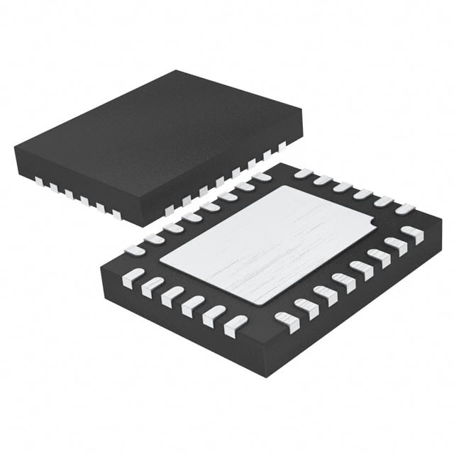
ICGOO电子元器件商城为您提供LT3070IUFD#PBF由LINEAR TECHNOLOGY设计生产,在icgoo商城现货销售,并且可以通过原厂、代理商等渠道进行代购。 LT3070IUFD#PBF价格参考。LINEAR TECHNOLOGYLT3070IUFD#PBF封装/规格:PMIC - 稳压器 - 线性, Linear Voltage Regulator IC Positive Adjustable 1 Output 0.8 V ~ 1.8 V 5A 28-QFN (4x5)。您可以下载LT3070IUFD#PBF参考资料、Datasheet数据手册功能说明书,资料中有LT3070IUFD#PBF 详细功能的应用电路图电压和使用方法及教程。
LT3070IUFD#PBF 是 Linear Technology(现已被 Analog Devices 收购)生产的一款高性能、低噪声、低压差线性稳压器,属于 PMIC(电源管理集成电路)系列。该器件广泛应用于需要高精度电压调节和低噪声电源的场景,尤其适用于对电源质量要求极高的应用。

 应用场景:

1. 通信设备:
   LT3070IUFD#PBF 适用于各种通信设备,如基站、路由器、交换机等。其低噪声特性可以确保射频(RF)电路和其他敏感电路的稳定工作,避免电源噪声对信号传输的影响。

2. 医疗设备:
   在医疗设备中,电源的稳定性至关重要。LT3070IUFD#PBF 可用于超声设备、心电图仪、监护仪等精密仪器,提供稳定的电源输出,确保设备的准确性和可靠性。

3. 测试与测量仪器:
   测试与测量仪器如示波器、频谱分析仪等对电源的要求非常高。LT3070IUFD#PBF 的低噪声和高精度特性使其成为这些设备的理想选择,能够提供干净的电源,减少测量误差。

4. 工业自动化:
   在工业控制系统中,PLC(可编程逻辑控制器)、传感器和执行器等设备需要稳定的电源支持。LT3070IUFD#PBF 可以为这些设备提供可靠的电源,确保系统的正常运行。

5. 汽车电子:
   汽车电子系统如车载信息娱乐系统、ADAS(高级驾驶辅助系统)等对电源的稳定性和抗干扰能力有严格要求。LT3070IUFD#PBF 的宽输入电压范围和低噪声特性使其适合在汽车环境中使用。

6. 便携式设备:
   对于便携式设备如笔记本电脑、平板电脑、移动电源等,LT3070IUFD#PBF 的高效能和小封装尺寸使其能够在有限的空间内提供稳定的电源,延长电池寿命。

 总结:
LT3070IUFD#PBF 凭借其低噪声、高精度和宽输入电压范围的特点,适用于多种对电源质量要求极高的应用场景,包括通信设备、医疗设备、测试与测量仪器、工业自动化、汽车电子和便携式设备等。
| 参数 | 数值 |
| 产品目录 | 集成电路 (IC) |
| 描述 | IC REG LDO ADJ 5A 28QFN |
| 产品分类 | |
| 品牌 | Linear Technology |
| 数据手册 | http://www.linear.com/docs/28460 |
| 产品图片 |
|
| 产品型号 | LT3070IUFD#PBF |
| rohs | 无铅 / 符合限制有害物质指令(RoHS)规范要求 |
| 产品系列 | - |
| 产品培训模块 | http://www.digikey.cn/PTM/IndividualPTM.page?site=cn&lang=zhs&ptm=24405 |
| 供应商器件封装 | 28-QFN(4x5) |
| 其它名称 | LT3070IUFDPBF |
| 包装 | 管件 |
| 安装类型 | 表面贴装 |
| 封装/外壳 | 28-WFQFN 裸露焊盘 |
| 工作温度 | -40°C ~ 125°C |
| 标准包装 | 73 |
| 特色产品 | http://www.digikey.cn/product-highlights/cn/zh/linear-technology-ldo-linear-regulators/2739 |
| 电压-跌落(典型值) | 0.085V @ 5A |
| 电压-输入 | 0.95 V ~ 3 V |
| 电压-输出 | 0.8 V ~ 1.8 V |
| 电流-输出 | 5A |
| 电流-限制(最小值) | 5.1A |
| 稳压器拓扑 | 正,可调式 |
| 稳压器数 | 1 |
| 视频文件 | http://www.digikey.cn/classic/video.aspx?PlayerID=1364138032001&width=640&height=505&videoID=602021952001 |


- 商务部:美国ITC正式对集成电路等产品启动337调查
- 曝三星4nm工艺存在良率问题 高通将骁龙8 Gen1或转产台积电
- 太阳诱电将投资9.5亿元在常州建新厂生产MLCC 预计2023年完工
- 英特尔发布欧洲新工厂建设计划 深化IDM 2.0 战略
- 台积电先进制程称霸业界 有大客户加持明年业绩稳了
- 达到5530亿美元!SIA预计今年全球半导体销售额将创下新高
- 英特尔拟将自动驾驶子公司Mobileye上市 估值或超500亿美元
- 三星加码芯片和SET,合并消费电子和移动部门,撤换高东真等 CEO
- 三星电子宣布重大人事变动 还合并消费电子和移动部门
- 海关总署:前11个月进口集成电路产品价值2.52万亿元 增长14.8%


PDF Datasheet 数据手册内容提取
LT3070 5A, Low Noise, Programmable Output, 85mV Dropout Linear Regulator FEATURES DESCRIPTION n Output Current: 5A The LT®3070 is a low voltage, UltraFast™ transient re- n Dropout Voltage: 85mV Typical sponse linear regulator. The device supplies up to 5A of n Digitally Programmable V : 0.8V to 1.8V output current with a typical dropout voltage of 85mV. OUT n Digital Output Margining: ±1%, ±3% or ±5% A 0.01µF reference bypass capacitor decreases output n Low Output Noise: 25µV (10Hz to 100kHz) voltage noise to 25µV . The LT3070’s high bandwidth RMS RMS n Parallel Multiple Devices for 10A or More permits the use of low ESR ceramic capacitors, saving n Precision Current Limit: ±20% bulk capacitance and cost. The LT3070’s features make n ±1% Accuracy Over Line, Load and Temperature it ideal for high performance FPGAs, microprocessors or n Stable with Low ESR Ceramic Output Capacitors sensitive communication supply applications. (15µF Minimum) Output voltage is digitally selectable in 50mV increments n High Frequency PSRR: 30dB at 1MHz over a 0.8V to 1.8V range. A margining function allows n Enable Function Turns Output On/Off the user to adjust system output voltage in increments of n VIOC Pin Controls Buck Converter to Maintain Low ±1%, ±3% or ±5%. The IC incorporates a unique tracking Power Dissipation and Optimize Efficiency function to control a buck regulator powering the LT3070’s n PWRGD/UVLO/Thermal Shutdown Flag input. This tracking function drives the buck regulator to n Current Limit with Foldback Protection maintain the LT3070’s input voltage to V + 300mV, OUT n Thermal Shutdown minimizing power dissipation. n 28-Lead (4mm × 5mm × 0.75mm) QFN Package Internal protection includes UVLO, reverse-current protec- APPLICATIONS tion, precision current limiting with power foldback and thermal shutdown. The LT3070 regulator is available in a n FPGA and DSP Supplies thermally enhanced 28-lead, 4mm × 5mm QFN package. n ASIC and Microprocessor Supplies L, LT, LTC, LTM, Linear Technology and the Linear logo are registered trademarks and n Servers and Storage Devices UltraFast and VLDO are trademarks of Linear Technology Corporation. All other trademarks are the property of their respective owners. Patents pending. n Post Buck Regulation and Supply Isolation TYPICAL APPLICATION Dropout Voltage 0.9V, 5A Regulator 150 50k VIN = VOUT(NOMINAL) VBIAS PWRGD 2.2V TO 3.6V 2.2µF 120 1V.2IVN IN BIASPWRGD E (mV) 330µF EN SENSE VOUT LTAG 90 VOUT = 1.8V VO0 LT3070 OUT 0.9V VO VBIAS = 3.3V VO1 2.2µF* 4.7µF* 10µF* 5A UT 60 O VO2 OP VOUT = 0.8V MARGSEL *X5R OR X7R CAPACITORS DR VBIAS = 2.5V 30 MARGTOL VIOC REF/BYP 1nF GND 0.01µF 0 0 1 2 3 4 5 3070 TA01a OUTPUT CURRENT (A) 3070 TA01b 3070fc 1 For more information www.linear.com/LT3070
LT3070 ABSOLUTE MAXIMUM RATINGS PIN CONFIGURATION (Note 1) IN, OUT .....................................................–0.3V to 3.3V TOP VIEW BIAS .............................................................–0.3V to 4V EN BIAS GND VO2 VO1 VO0 VO2, VO1, VO0 Inputs ....................................–0.3V to 4V 28 27 26 25 24 23 MARGSEL, MARGTOL Input ........................–0.3V to 4V VIOC 1 22 MARGTOL EN Input .......................................................–0.3V to 4V PWRGD 2 21 MARGSEL REF/BYP 3 20 GND SENSE Input .................................................–0.3V to 4V GND 4 29 19 SENSE VIOC, PWRGD Outputs ................................–0.3V to 4V IN 5 GND 18 OUT REF/BYP Output ...........................................–0.3V to 4V IN 6 17 OUT Output Short-Circuit Duration……...................Indefinite IN 7 16 OUT Operating Junction Temperature (Note 2) IN 8 15 OUT LT3070E/LT3070I ............................. –40°C to 125°C 9 10 11 12 13 14 D D D D D D LT3070MP .........................................–55°C to 125°C N N N N N N G G G G G G Storage Temperature Range ..................–65°C to 150°C UFD PACKAGE 28-LEAD (4mm × 5mm) PLASTIC QFN TJMAX = 125°C, θJA = 30°C/W TO 35°C/W EXPOSED PAD (PIN 29) IS GND, MUST BE SOLDERED TO PCB ORDER INFORMATION LEAD FREE FINISH TAPE AND REEL PART MARKING* PACKAGE DESCRIPTION TEMPERATURE RANGE LT3070EUFD#PBF LT3070EUFD#TRPBF 3070 28-Lead (4mm × 5mm) Plastic QFN –40°C to 125°C LT3070IUFD#PBF LT3070IUFD#TRPBF 3070 28-Lead (4mm × 5mm) Plastic QFN –40°C to 125°C LT3070MPUFD#PBF LT3070MPUFD#TRPBF 3070 28-Lead (4mm × 5mm) Plastic QFN –55°C to 125°C LEAD BASED FINISH TAPE AND REEL PART MARKING* PACKAGE DESCRIPTION TEMPERATURE RANGE LT3070EUFD LT3070EUFD#TR 3070 28-Lead (4mm × 5mm) Plastic QFN –40°C to 125°C LT3070IUFD LT3070IUFD#TR 3070 28-Lead (4mm × 5mm) Plastic QFN –40°C to 125°C LT3070MPUFD LT3070MPUFD#TR 3070 28-Lead (4mm × 5mm) Plastic QFN –55°C to 125°C Consult LTC Marketing for parts specified with wider operating temperature ranges. *The temperature grade is identified by a label on the shipping container. For more information on lead free part marking, go to: http://www.linear.com/leadfree/ For more information on tape and reel specifications, go to: http://www.linear.com/tapeandreel/ 3070fc 2 For more information www.linear.com/LT3070
LT3070 ELECTRICAL CHARACTERISTICS The l denotes the specifications which apply over the full operating temperature range, otherwise specifications are at T = 25°C. C = 15µF (Note 9), V = V + 0.3V (Note 5), V = 2.5V unless A OUT IN OUT BIAS otherwise noted. PARAMETER CONDITIONS MIN TYP MAX UNITS IN Pin Voltage Range V ≥ V + 150mV, I = 5A l 0.95 3.0 V IN OUT OUT BIAS Pin Voltage Range (Note 3) l 2.2 3.6 V Regulated Output Voltage V = 0.8V, 10mA ≤ I ≤ 5A, 1.05V ≤ V ≤ 1.25V l 0.792 0.800 0.808 V OUT OUT IN V = 0.9V, 10mA ≤ I ≤ 5A, 1.15V ≤ V ≤ 1.35V l 0.891 0.900 0.909 V OUT OUT IN V = 1V, 10mA ≤ I ≤ 5A, 1.25V ≤ V ≤ 1.45V l 0.990 1.000 1.010 V OUT OUT IN V = 1.1V, 10mA ≤ I ≤ 5A, 1.35V ≤ V ≤ 1.55V l 1.089 1.100 1.111 V OUT OUT IN V = 1.2V, 10mA ≤ I ≤ 5A, 1.45V ≤ V ≤ 1.65V, V = l 1.188 1.200 1.212 V OUT OUT IN BIAS 3.3V l 1.485 1.500 1.515 V V = 1.5V, 10mA ≤ I ≤ 5A, 1.75V ≤ V ≤ 1.95V, V = l 1.782 1.800 1.818 V OUT OUT IN BIAS 3.3V V = 1.8V, 10mA ≤ I ≤ 5A, 2.05V ≤ V ≤ 2.25V, V = OUT OUT IN BIAS 3.3V Regulated Output Voltage Margining MARGTOL = 0V, MARGSEL = V l 0.8 1 1.2 % BIAS (Note 3) MARGTOL = 0V, MARGSEL = 0V, I = 10mA l –1.2 –1 –0.8 % OUT MARGTOL = FLOAT, MARGSEL = V l 2.7 3 3.3 % BIAS MARGTOL = FLOAT, MARGSEL = 0V, I = 10mA l –3.3 –3 –2.7 % OUT MARGTOL = V , MARGSEL= V l 4.6 5 5.4 % BIAS BIAS MARGTOL = V , MARGSEL = 0V, I = 10mA l –5.4 –5 –4.6 % BIAS OUT Line Regulation to V V = 0.8V, ∆V = 1.05V to 2.7V, V = 3.3V, I = 10mA l 1.0 mV IN OUT IN BIAS OUT V = 1.8V, ∆V = 2.05V to 2.7V, V = 3.3V, I = 10mA l 1.0 mV OUT IN BIAS OUT Line Regulation to V V = 0.8V, ∆V = 2.2V to 3.6V, V = 1.1V, I = 10mA l 2.0 mV BIAS OUT BIAS IN OUT V = 1.8V, ∆V = 3.25V to 3.6V, V = 2.1V, I = 10mA l 1.0 mV OUT BIAS IN OUT Load Regulation, V = 2.5V, V = 1.05V, V = 0.8V –1.5 –3.0 mV BIAS IN OUT ∆I = 10mA to 5A l –5.5 mV OUT V = 2.5V, V = 1.25V, V = 1.0V –2 –4.0 mV BIAS IN OUT l –7.5 mV V = 3.3V, V = 1.45V, V = 1.2V –2 –4.0 mV BIAS IN OUT l –7.5 mV V = 3.3V, V = 1.75V, V = 1.5V –2.5 –5.0 mV BIAS IN OUT l –9.0 mV V = 3.3V, V = 2.05V, V = 1.8V –3 –7.0 mV BIAS IN OUT l –13 mV Dropout Voltage, I = 1A, V = 1V l 20 35 mV OUT OUT VIN = VOUT(NOMINAL) (Note 6) I = 2.5A, V = 1V 50 65 mV OUT OUT l 85 mV I = 5A, V = 1V 85 120 mV OUT OUT l 150 mV SENSE Pin Current V = 1.1V, V = 0.8V l 35 50 65 µA IN SENSE V = 3.3V, V = 2.1V, V = 1.8V l 200 300 400 µA BIAS IN SENSE 3070fc 3 For more information www.linear.com/LT3070
LT3070 ELECTRICAL CHARACTERISTICS The l denotes the specifications which apply over the full operating temperature range, otherwise specifications are at T = 25°C. C = 15µF (Note 9), V = V + 0.3V (Note 5), V = 2.5V unless A OUT IN OUT BIAS otherwise noted. PARAMETER CONDITIONS MIN TYP MAX UNITS Ground Pin Current, I = 10mA l 0.65 1.1 1.8 mA OUT V = 1.3V, V = 1V I = 5A l 0.9 1.35 2.3 mA IN OUT OUT BIAS Pin Current in Nap Mode EN = Low l 120 200 320 µA BIAS Pin Current, I = 10mA l 0.75 1.08 1.5 mA OUT V = 1.3V, V = 1V I = 100mA l 1.25 1.8 2.4 mA IN OUT OUT I = 500mA l 2.0 3.0 4.0 mA OUT I = 1A l 2.6 3.8 5.0 mA OUT I = 2.5A l 3.5 5.2 7.0 mA OUT I = 5A l 4.5 6.9 10.0 mA OUT Current Limit (Note 5) V – V < 0.3V, V = 3.3V l 5.1 6.4 7.7 A IN OUT BIAS V – V = 1.0V, V = 3.3V l 3.2 4.5 5.8 A IN OUT BIAS V – V = 1.7V, V = 3.3V l 1.2 2.5 4.3 A IN OUT BIAS Reverse Output Current (Note 8) V = 0V, V = 1.8V l 300 450 µA IN OUT PWRGD V Threshold Percentage of V , V Rising l 87 90 93 % OUT OUT(NOMINAL) OUT Percentage of V , V Falling l 82 85 88 % OUT(NOMINAL) OUT PWRGD V I = 200µA (Fault Condition) l 50 150 mV OL PWRGD V Undervoltage Lockout V Rising l 1.1 1.55 2.1 V BIAS BIAS V Falling l 0.9 1.4 1.7 V BIAS V -V Servo Voltage by VIOC l 250 300 350 mV IN OUT VIOC Output Current V = V + 150mV, Sourcing Out of the Pin l 160 235 310 µA IN OUT(NOMINAL) V = V + 450mV, Sinking Into the Pin l 170 255 340 µA IN OUT(NOMINAL) V Input Threshold (Logic-0 State), Input Falling l 0.25 V IL V , V , V , MARGSEL, MARGTOL O2 O1 O0 V Input Range (Logic-Z State), l 0.75 V – 0.9 V IZ BIAS V , V , V , MARGSEL, MARGTOL O2 O1 O0 V Input Threshold (Logic-1 State), Input Rising l V – 0.25 V IH BIAS V , V , V , MARGSEL, MARGTOL O2 O1 O0 Input Hysteresis (Both Thresholds), 60 mV V , V , V , MARGSEL, MARGTOL O2 O1 O0 Input Current High, V = V = 2.5V, Current Flows Into Pin l 25 40 µA IH BIAS V , V , V , MARGSEL, MARGTOL O2 O1 O0 Input Current Low, V = 0V, V = 2.5V, Current Flows Out of Pin l 25 40 µA IL BIAS V , V , V , MARGSEL, MARGTOL O2 O1 O0 EN Pin Threshold V = Off to On, V = 2.5V l 1.4 V OUT BIAS V = On to Off, V = 2.5V l 0.9 V OUT BIAS V = Off to On, V =2.2V to 3.6V l 0.56 • V V OUT BIAS BIAS V = On to Off, V =2.2V to 3.6V l 0.36 • V V OUT BIAS BIAS EN Pin Logic High Current V = V = 2.5V l 2.5 4.0 6.5 µA EN BIAS 3070fc 4 For more information www.linear.com/LT3070
LT3070 ELECTRICAL CHARACTERISTICS The l denotes the specifications which apply over the full operating temperature range, otherwise specifications are at T = 25°C. C = 15µF (Note 9), V = V + 0.3V (Note 5), V = 2.5V unless A OUT IN OUT BIAS otherwise noted. PARAMETER CONDITIONS MIN TYP MAX UNITS EN Pin Logic Low Current V = 0V l 0.1 µA EN V Ripple Rejection V = V + 1.5V , V =0.5V , f = 120Hz, 75 dB BIAS BIAS OUT AVG RIPPLE P-P RIPPLE V – V = 300mV, I = 2.5A IN OUT OUT V Ripple Rejection V = 2.5V, V = 50mV , f = 120Hz, 66 dB IN BIAS RIPPLE P-P RIPPLE (Notes 3, 4, 5) V – V = 300mV, I = 2.5A IN OUT OUT Reference Voltage Noise C = 10nF, BW = 10Hz to 100kHz 10 µV REF/BYP RMS (REF/BYP Pin) Output Voltage Noise V = 1V, I = 5A, C = 10nF, C = 15µF, 25 µV OUT OUT REF/BYP OUT RMS BW = 10Hz to 100kHz Note 1: Stresses beyond those listed under Absolute Maximum Ratings Note 5: The LT3070 incorporates safe operating area protection circuitry. may cause permanent damage to the device. Exposure to any Absolute Current limit decreases as the VIN-VOUT voltage increases. Current limit Maximum Rating condition for extended periods may affect device foldback starts at VIN – VOUT > 500mV. See the Typical Performance reliability and lifetime. Characteristics for a graph of Current Limit vs VIN – VOUT voltage. The Note 2: The LT3070 regulators are tested and specified under pulse load current limit foldback feature is independent of the thermal shutdown conditions such that T ≅ T . The LT3070E is 100% tested at T = 25°C. circuity. J A A Performance at –40°C and 125°C is assured by design, characterization Note 6: Dropout voltage, VDO, is the minimum input to output voltage and correlation with statistical process controls. The LT3070I is differential at a specified output current. In dropout, the output voltage guaranteed over the –40°C to 125°C operating junction temperature range. equals VIN – VDO. The LT3070MP is 100% tested and guaranteed over the –55°C to 125°C Note 7: GND pin current is tested with V = V + 300mV and a IN OUT(NOMINAL) operating junction temperature range. current source load. VIOC is a buffered output determined by the value of Note 3: To maintain proper performance and regulation, the BIAS supply VOUT as programmed by the VO2-VO0 pins. VIOC’s output is independent voltage must be higher than the IN supply voltage. For a given V , the of the margining function. OUT BIAS voltage must satisfy the following conditions: 2.2V ≤ VBIAS ≤ 3.6V Note 8: Reverse output current is tested with the IN pins grounded and the and VBIAS ≥ (1.25 • VOUT + 1V). For VOUT ≤ 0.95V, the minimum BIAS OUT + SENSE pins forced to the rated output voltage. This is measured as voltage is limited to 2.2V. current into the OUT + SENSE pins. Note 4: Operating conditions are limited by maximum junction Note 9: Frequency Compensation: The LT3070 must be frequency temperature. The regulated output voltage specification does not apply compensated at its OUT pins with a minimum C of 15µF configured OUT for all possible combinations of input voltage and output current. When as a cluster of (15×) 1µF ceramic capacitors or as a graduated cluster operating at maximum output current, limit the input voltage range to of 10µF/4.7µF/2.2µF ceramic capacitors of the same case size. Linear VIN < VOUT + 500mV. Technology only recommends X5R or X7R dielectric capacitors. 3070fc 5 For more information www.linear.com/LT3070
LT3070 TYPICAL PERFORMANCE CHARACTERISTICS Dropout Voltage vs I Dropout Voltage vs Temperature Dropout Voltage vs Temperature OUT 150 30 100 VIN = VOUT(NOMINAL) VIN = VOUT(NOMINAL) VIN = VOUT(NOMINAL) TJ = 25°C IOUT = 1A 90 IOUT = 2.5A 25 120 80 V) V) V) m m m 70 E ( E ( 20 E ( AG 90 AG AG 60 VOLT VVBOIAUST == 13..83VV VOLT 15 VOLT 50 UT 60 UT UT 40 O O O OP VOUT = 0.8V OP 10 OP 30 DR VBIAS = 2.5V DR DR 30 5 VOUT = 1.8V, VBIAS = 3.3V 20 VOUT = 1.8V, VBIAS = 3.3V VOUT = 0.8V, VBIAS = 2.5V 10 VOUT = 0.8V, VBIAS = 2.5V VOUT = 1.2V, VBIAS = 3.3V VOUT = 1.2V, VBIAS = 3.3V 0 0 0 0 1 2 3 4 5 –75–50–25 0 25 50 75 100125 150175 –75–50–25 0 25 50 75 100125150175 OUTPUT CURRENT (A) TEMPERATURE (°C) TEMPERATURE (°C) 3070 G01 3070 G02 3070 G03 Output Voltage (0.8V) Dropout Voltage vs Temperature Dropout Voltage vs V vs Temperature BIAS 150 200 0.808 VIN = VOUT(NOMINAL) IOUT = 5A ILOAD = 10mA IOUT = 5A 180 TJ = 25°C 0.806 120 160 mV) mV)140 V)0.804 AGE ( 90 AGE (120 AGE (0.802 DROPOUT VOLT 60 DROPOUT VOLT1680000 OUTPUT VOLT000...877099086 30 40 VOUT = 1.8V, VBIAS = 3.3V OUT = 1.8V VOUT = 0.8V, VBIAS = 2.5V 20 OUT = 1.5V 0.794 VOUT = 1.2V, VBIAS = 3.3V OUT = 0.8V 0 0 0.792 –75–50–25 0 25 50 75 100125150175 2.2 2.4 2.6 2.8 3.0 3.2 3.4 3.6 –75–50–25 0 25 50 75 100125150175 TEMPERATURE (°C) BIAS VOLTAGE (V) TEMPERATURE (°C) 3070 G04 3070 G05 3070 G06 Output Voltage (1V) Output Voltage (1.2V) Output Voltage (1.5V) vs Temperature vs Temperature vs Temperature 1.010 1.212 1.515 ILOAD = 10mA ILOAD = 10mA ILOAD = 10mA 1.008 1.208 1.510 1.006 V)1.004 V) V) E ( E (1.204 E (1.505 AG1.002 AG AG T T T L L L O1.000 O1.200 O1.500 V V V T T T U0.998 U U P P P OUT0.996 OUT1.196 OUT1.495 0.994 1.192 1.490 0.992 0.990 1.188 1.485 –75–50–25 0 25 50 75 100125150175 –75–50–25 0 25 50 75 100125 150175 –75–50–25 0 25 50 75 100125 150175 TEMPERATURE (°C) TEMPERATURE (°C) TEMPERATURE (°C) 3070 G07 3070 G08 3070 G09 3070fc 6 For more information www.linear.com/LT3070
LT3070 TYPICAL PERFORMANCE CHARACTERISTICS Output Voltage (1.8V) REF/BYP Pin Voltage vs Temperature GND Pin Current vs I vs Temperature OUT 1.818 3.0 606 ILOAD = 10mA VIN = VOUT + 300mV CREF/BYP = 0.01µF 1.814 TJ = 25°C 2.5 604 1.810 GE (V)1.806 NT (mA) 2.0 GE (mV)602 UTPUT VOLTA111...778990482 D PIN CURRE 11..05 F/BYP VOLTA569080 O1.790 GN RE 0.5 VOUT = 1.8V, VBIAS = 3.3V 596 1.786 VOUT = 1.2V, VBIAS = 3.3V VOUT = 0.8V, VBIAS = 2.5V 1.782 0 594 –75–50–25 0 25 50 75 100125150175 0 1 2 3 4 5 –75–50–25 0 25 50 75 100125 150175 TEMPERATURE (°C) OUTPUT CURRENT (A) TEMPERATURE (°C) 3070 G10 3070 G12 3070 G11 BIAS Pin Undervoltage Lockout BIAS Pin Current in Nap Mode BIAS Pin Current vs I Threshold OUT 400 10 2.5 VBIAS = 2.5V VIN = VOUT + 300mV 350 VEN = 0V 9 TJ = 25°C BIAS PIN CURRENT (µA) 322110505000000 BIAS PIN CURRENT (mA) 6842573 VVBOIAUST == 13..83VV VVOBIUATS == 02..85VV VLO THRESHOLD VOLTAGE (V) 0211....5005 VBIAS FALVLBINIAGS RISING U 50 1 0 0 0 –75–50–25 0 25 50 75 100125150175 0 1 2 3 4 5 –75–50–25 0 25 50 75 100125150175 TEMPERATURE (°C) OUTPUT CURRENT (A) TEMPERATURE (°C) 3070 G13 3070 G14 3070 G15 Enable Pin Threshold and EN Pin Thresholds Hysteresis vs V PWRGD Threshold Voltage BIAS 2.0 4.0 1.00 1.8 VBIAS = 2.5V TTYJ P=I –C5A5L° HC YTSOT 1E2R5E°SCIS = 150mV VBIAS = 2.5V HOLD (V) 11..64 EN PIN RISING ESHOLD (V) 233...505 VBIAS LTAGE (V)0.95 VOUT = 1V S 1.2 R O ENABLE PIN THRE 0010....8406 EN PIN FALLING NABLE/DISABLE TH 211...050 TYP ENABLTEYP DISAMBMLAEIXN E DNIASBALBELE RGD TRESHOLD V00..8950 VVOOUUTT F RAILSLIINNGG E 0.5 W 0.2 P 0 0 –75–50–25 0 25 50 75 100125150175 2 2.5 3 3.5 4 0.80 TEMPERATURE (°C) BIAS VOLTAGE (V) –75 –50–25 0 25 50 75 100125150175 3070 G16 3070 G17 TEMPERATURE (°C) 3070 G18 3070fc 7 For more information www.linear.com/LT3070
LT3070 TYPICAL PERFORMANCE CHARACTERISTICS Logic Input Threshold Voltages Logic Input Threshold Voltages PWRGD V vs Temperature Logic Low to Hi-Z State Transitions Logic Hi-Z to High State Transitions OL 100 0.8 3.0 OLTAGE (mV) 8600 IVPBWIARSG =D 2=. 52V00µA HOLD VOLTAGE (V) 00..76 SFOERE AMLPOOPRGILNEIICCP D AULETTOTI OWRANII SLTSSION I NGHFi-OZRMATION HOLD VOLTAGE (V) 22..98 VLRSFOOBEEIREGLA A ISAMCT P= IOHPV 3RiLE-.EZ3I TC VDTOAOE TVT IHOBAIINIAGLISSNHS PVI TNUOHFTLOR TRREAISMSGHIEANOTGLIODN IS WRGD V VOL 40 NPUT THRES 0.5 LOIGNIPCU HT i-FZA LTLOI NLGOW NPUT THRES 2.7 LOIGNIPCU HTI GFAHL TLOIN HGi-Z LOGIC Hi-Z TO HIGH P 20 C I 0.4 C I 2.6 GI GI O O L L 0 0.3 2.5 –75 –50 –25 0 25 50 75 100 125 150 –75–50–25 0 25 50 75 100125150175 –75–50–25 0 25 50 75 100125150175 TEMPERATURE (°C) TEMPERATURE (°C) TEMPERATURE (°C) 3070 G19 3070 G20 3070 G21 Logic Pin Input Current, Logic Pin Input Current, EN Pin Logic High Current High State Low State 6.0 40 40 VEN = VBIAS = 2.5V VLOGIC = VBIAS = 2.5V VBIAS = 2.5V EN PIN LOGIC HIGH CURRENT (µA) 453234521.........000055555 LOGIC PIN INPUT CURRENT (µA) 3322115050505 CURRENT FLOWS INTO THE PIN LOGIC PIN INPUT CURRENT (µA) 3322115050505 VCULORGRICE N= T0 VFLOWS OUT OF THE PIN 1.0 0 –75–50–25 0 25 50 75 100125150175 –75–50–25 0 25 50 75 100125150175 0 –75–50–25 0 25 50 75 100125150175 TEMPERATURE (°C) TEMPERATURE (°C) TEMPERATURE (°C) 3070 G22 3070 G23 3070 G24 SENSE Pin Current SENSE Pin Current Current Limit vs Temperature 65 400 7.50 VBIAS = 2.5V VBIAS = 3.3V VIN – VOUT(NOMINAL) = 300mV 60 VOUT = 0.8V 375 VOUT = 1.8V 7.25 CURRENT FLOWS INTO SENSE CURRENT FLOWS INTO SENSE 7.00 A) 55 A) 350 RENT (µ 50 RENT (µ 325 MIT (A)66..7550 CUR 45 CUR 300 T LI6.25 NSE PIN 40 NSE PIN 275 CURREN65..0705 E 35 E 250 S S 5.50 VOUT = 1.8V, VBIAS = 3.3V 30 225 5.25 VOUT = 1.2V, VBIAS = 3.3V VOUT = 0.8V, VBIAS = 2.5V 25 200 5.00 –75–50–25 0 25 50 75 100125150175 –75–50–25 0 25 50 75 100125150175 –75–50–25 0 25 50 75 100125150175 TEMPERATURE (°C) TEMPERATURE (°C) TEMPERATURE (°C) 3070 G25 3070 G26 3070 G27 3070fc 8 For more information www.linear.com/LT3070
LT3070 TYPICAL PERFORMANCE CHARACTERISTICS Current Limit vs V – V BIAS Pin Ripple Rejection IN Pin Ripple Rejection IN OUT 8 100 80 VBIAS = 3.3V VIN = 1.3V 7 TJ = 25°C 90 VOUT = 1V 70 dB) 80 IOUT = 5A B) NT LIMIT (A) 465 LE REJECTION ( 675000 COUT = 10µF + 4.7µF + 2.2µF E REJECTION (d 456000 E P L CURR 231 VVOOUUTT == 11..82VV BIAS PIN RIP 21430000 VVBBIIAASS == 22..57VV ++ 550000mmVVPP--PP IN PIN RIPP 213000 VVVOIBNIUA =TS =1CC= . OO132VUUV.5TT +V == 5 11016m7.9VµµPFF-P RIPPLE VOUT = 0.8V VBIAS = 3.3V + 500mVP-P IOUT = 1A 0 0 0 0 0.25 0.50 0.75 1.00 1.25 1.50 1.75 2.00 10 100 1k 10k 100k 1M 10M 10 100 1k 10k 100k 1M 10M IN-TO-OUT VOLTAGE DIFFERENTIAL (V) FREQUENCY (Hz) FREQUENCY (Hz) 3070 G28 3070 G29 3070 G30 IN Pin Ripple Rejection IN Pin Ripple Rejection IN Pin Ripple Rejection vs VIN – VOUT , 1V/5A vs VIN – VOUT , 1V/2.5A 80 120 120 110 50mVP-P RIPPLE ON VIN 110 50mVP-P RIPPLE ON VIN N (dB) 6700 19000 TVCABO IU=AT S2 =5= ° 12C6.5.9VμF 19000 TVCABO IU=AT S2 =5= ° 12C6.5.9VμF RIPPLE AT f = 10kHz ECTIO 50 B) 7800 RIPPLE AT f = 10kHz B) 7800 REJ 40 R (d 60 R (d 60 RIPPLE AT f = 100kHz IN PIN RIPPLE 2300 VVOINU =T =1CC .OO13VUUVTT + == 5 11016m7.9VµµPFF-P RIPPLE PSR 23450000 RRIIPPPPLLEE AATT ff == 110M0HkzHz PSR 23450000 RIPPLE AT f = 1MHz 10 VBIAS = 2.5V 10 10 0 IOUT = 5A 0 0 10 100 1k 10k 100k 1M 10M 0 0.10.20.30.40.50.60.70.80.91.01.11.2 0 0.10.20.30.40.50.60.70.80.91.01.11.2 AVERAGE INPUT/OUTPUT DIFFERENTIAL (V) AVERAGE INPUT/OUTPUT DIFFERENTIAL (V) FREQUENCY (Hz) 3070 G32 3070 G33 3070 G31 IN Pin Ripple Rejection IN Pin Ripple Rejection IN Pin Ripple Rejection vs VIN – VOUT , 1V/1A vs VIN – VOUT , 1V/5A vs VIN – VOUT , 1V/2.5A 120 120 120 110 50mVP-P RIPPLE ON VIN 110 50mVP-P RIPPLE ON VIN 110 50mVP-P RIPPLE ON VIN 100 VCBOIUATS == 126.5.9VμF RIPPLE AT f = 10kHz 100 VCBOIUATS == 121.57VμF 100 VCBOIUATS == 121.57VμF 90 TA = 25°C 90 TA = 25°C 90 TA = 25°C 80 80 80 RIPPLE AT f = 10kHz RIPPLE AT f = 10kHz PSRR (dB) 567000 RIPPLE AT f = 100kHz PSRR (dB) 567000 RIPPLE AT f = 1MHz PSRR (dB) 567000 RIPPLE AT f = 1MHz 40 40 RIPPLE AT f = 100kHz 40 RIPPLE AT f = 100kHz 30 RIPPLE AT f = 1MHz 30 30 20 20 20 10 10 10 0 0 0 0 0.10.20.30.40.50.60.70.80.91.01.11.2 0 0.10.20.30.40.50.60.70.80.91.01.11.2 0 0.10.20.30.40.50.60.70.80.91.01.11.2 AVERAGE INPUT/OUTPUT DIFFERENTIAL (V) AVERAGE INPUT/OUTPUT DIFFERENTIAL (V) AVERAGE INPUT/OUTPUT DIFFERENTIAL (V) 3070 G34 3070 G35 3070 G36 3070fc 9 For more information www.linear.com/LT3070
LT3070 TYPICAL PERFORMANCE CHARACTERISTICS IN Pin Ripple Rejection Minimum BIAS Voltage vs VIN – VOUT , 1V/1A vs Temperature Minimum BIAS Voltage vs IOUT 120 4.0 3.6 B)117890100000 TVC5A0BO mIU=AT SV2 =P5= -° 1P2C1 .R57IVμPFPLE ONR VIPINPLE AT f = 10kHz OLTAGE (V) 3333....2648 IOUT = 5A VVVOOOUUUTTT === 110...828VVV OLTAGE (V) 333...240 V∆IVNO =U TVVVVV O=OOOO UUUUU–TTTTT1 ( ====N% O0111,M ....T8852IJVNVVV =A T L2O) 5 +1° CV300mV d V V PSRR ( 5600 RIPPLE AT f = 1MHz M BIAS 23..80 M BIAS 22..86 40 RIPPLE AT f = 100kHz MU 2.6 MU 30 MINI 2.4 MINI 2.4 20 2.2 10 2.2 0 2.0 2.0 0 0.10.20.30.40.50.60.70.80.91.01.11.2 –75–50–25 0 25 50 75 100125150175 0 1 2 3 4 5 AVERAGE INPUT/OUTPUT DIFFERENTIAL (V) TEMPERATURE (°C) OUTPUT CURRENT (A) 3070 G37 3070 G38 3070 G39 Minimum BIAS Voltage vs V Load Regulation Bias Voltage Line Regulation OUT 3.4 0 800 IOUT = 5A VBIAS = 2.2V TO 3.6V 3.2 TJ = 25°C V) 700 VIN = 1.1V GE (V) 3.0 mV) –2 ATION (µ 600 VIOOUUTT = = 1 00.m8VA MINIMUM BIAS VOLTA 22222.....86420 LOAD REGULATION ( –––864 V∆VIBINOIA U=ST V =VV=O OO 31UUU.0T3TT(0V N==mO 01AM.. 82ITNVVOA L5) A+ 300mV BIAS VOLTAGE LINE REGUL 543210000000000 VOUT = 1.8V 1.8 –10 0 0.7 0.9 1.1 1.3 1.5 1.7 1.9 –75–50–25 0 25 50 75 100125150175 –75–50–25 0 25 50 75 100125150175 OUTPUT VOLTAGE (V) TEMPERATURE (°C) TEMPERATURE (°C) 3070 G40 3070 G41 3070 G42 Bias Voltage Line Regulation Input Voltage Line Regulation Input Voltage Line Regulation 400 300 300 V) 300 VVBINIA =S 2=. 13V.25V TO 3.6V µV) VVBINIA =S 1=. 035.3VV TO 2.7V µV) VVBINIA =S 2=. 035.3VV TO 2.7V BIAS VOLTAGE LINE REGULATION (µ–––2112300000000000 VIOOUUTT = = 1 10.m8VA NPUT VOLTAGE LINE REGULATION (12120055500000 VIOOUUTT = = 1 00.m8VA NPUT VOLTAGE LINE REGULATION (12120055500000 VIOOUUTT = = 1 10.m8VA I I –400 0 0 –75–50–25 0 25 50 75 100125150175 –75–50–25 0 25 50 75 100125 150175 –75–50–25 0 25 50 75 100125 150175 TEMPERATURE (°C) TEMPERATURE (°C) TEMPERATURE (°C) 3070 G43 3070 G44 3070 G45 3070fc 10 For more information www.linear.com/LT3070
LT3070 TYPICAL PERFORMANCE CHARACTERISTICS Output Voltage Start-Up Time vs CREF/BYP Nap Mode Recovery Time vs IOUT Output Noise Spectral Density 20 400 1.0 OUTPUT VOLTAGE START-UP TIME (ms) 11111268404862 SISVICTNOJETBOU FIEAU=ATO TRS A2R= T =5P= M-1 °P 1U2C0AL0P.mTI5µ CIDVAFOA E+NTTT OI 4AFO .OI37NL.RµS3SF V + 2.2µF NAP MODE RECOVERY TIME (µs) 21133200505550000000 VEITVONJBINU I= A T== S 2 = L V5=CVCVVC O5°O OOOOOOW3CAUUUUUUU. T3 (TTTTTT(TSV N======OEO T111101MH ..11.1B)2I88 777GV+YVVµµµH , ,,3FFFA0 R0EmSVISTOR LOAD) NOISE SPECTRAL DENSITY (µV/√Hz)0.00.11 VICCVOBOORUIUUEATFTTS /= B === Y5 11P2AV6 .=5.9 V0µ.F01µF 0 0 0.001 0 0.1 0.2 0.3 0.4 0.5 0 1 2 3 4 5 10 100 1k 10k 100k REF/BYP CAPACITANCE (µF) OUTPUT CURRENT (A) FREQUENCY (Hz) 3070 G46 3070 G47 3070 G48 RMS Output Noise Input Voltage Line Transient vs Output Current Output Noise (10Hz to 100kHz) Response 80 VIN = VOUT(NOMINAL) + 300mV 70 VBIAS = 3.3V COUT = 16.9µF )MS 60 1mVV/ODUIVT R µV 50 VOUT NOISE ( 40 100µV/DIV 50mV/DVIIVN T U 30 P T U O 20 100 VVVOOOUUUTTT === 110...828VVV VCIOOOUUUTTT = == 5 11AV6.9µF 1ms/DIV 3070 G50 VVIOIONUU T=T = =1 5 .13AVV 20µs/DIV 3070 G51 0.01 0.1 1 10 COUT = 16.9µF OUTPUT CURRENT (A) 3070 G49 Bias Voltage Line Transient VIOC Amplifier IN-to-OUT Servo VIOC Amplifier Output Current Response Voltage vs Temperature 350 300 10mVV/ODUIVT AGE (mV) 333400 VBIAS = 2.5V RENT (µA)275 IVIOC SOURCING VBIAS UT SERVO VOLT 323319020000 R OUTPUT CUR225205 IVIOC SINKING 200mV/DIV N-TO-O 280 MPLIFIE200 VVIBNIA =S 1=. 32V.5V 20µs/DIV 3070 G52 VIOC I 227600 VIOC A175 VOUT = 1V 250 150 IOUT = 5A –75–50–25 0 25 50 75 100125150175 –75–50–25 0 25 50 75 100125 150175 COUT = 16.9µF TEMPERATURE (°C) TEMPERATURE (°C) 3070 G53 3070 G54 3070fc 11 For more information www.linear.com/LT3070
LT3070 TYPICAL PERFORMANCE CHARACTERISTICS Transient Load Response Transient Load Response VOUT VOUT 50mV/DIV 50mV/DIV AC-COUPLED AC-COUPLED IOUT IOUT 2A/DIV 2A/DIV ∆I = 500mA ∆I = 500mA TO 5A TO 5A VOUT = 1V 20µs/DIV 3070 G55 VOUT = 1V 20µs/DIV 3070 G56 COUT = 10µF + 4.7µF + 2.2µF COUT = 117µF IOUT tRISE/tFALL = 100ns IOUT tRISE/tFALL = 100ns Transient Load Response Transient Load Response VOUT VOUT 50mV/DIV 50mV/DIV AC-COUPLED AC-COUPLED IOUT IOUT 2A/DIV 2A/DIV ∆I = 500mA ∆I = 500mA TO 5A TO 5A VOUT = 1V 20µs/DIV 3070 G57 VOUT = 1V 20µs/DIV 3070 G58 COUT = 10µF + 4.7µF + 2.2µF COUT = 117µF IOUT tRISE/tFALL = 1µs IOUT tRISE/tFALL = 1µs 3070fc 12 For more information www.linear.com/LT3070
LT3070 PIN FUNCTIONS VIOC (Pin 1): Voltage for In-to-Out Control. The IC incorpo- IN (Pins 5, 6, 7, 8): Input Supply. These pins supply rates a unique tracking function to control a buck regulator power to the high current pass transistor. Tie all IN pins powering the LT3070’s input. The VIOC pin is the output together for proper performance. The LT3070 requires a of this tracking function that drives the buck regulator to bypass capacitor at IN to maintain stability and low input maintain the LT3070’s input voltage at V + 300mV. impedance over frequency. A 47µF input bypass capacitor OUT This function maximizes efficiency and minimizes power suffices for most battery and power plane impedances. dissipation. See the Applications Information section for Minimizing input trace inductance optimizes performance. more information on proper control of the buck regulator. Applications that operate with low V -V differential IN OUT voltages and that have large, fast load transients may require PWRGD (Pin 2): Power Good. The PWRGD pin is an open- much higher input capacitor requirements to prevent the drain NMOS output that actively pulls low if any one of input supply from drooping and allowing the regulator to these fault modes is detected: enter dropout. See the Applications Information section • VOUT is less than 90% of VOUT(NOMINAL) on the rising for more information on input capacitor requirements. edge of V . OUT OUT (Pins 15, 16, 17, 18): Output. These pins supply • VOUT drops below 85% of VOUT(NOMINAL) for more than power to the load. Tie all OUT pins together for proper 25µs. performance. A minimum output capacitance of 15µF is required for stability. LTC recommends low ESR, X5R or • Junction temperature typically exceeds 145°C. X7R dielectric ceramic capacitors for best performance. • V is less than its undervoltage lockout threshold. BIAS A parallel ceramic capacitor combination of 10µF + 4.7µF • The OUT-to-IN reverse-current detector activates. + 2.2µF or 15 1µF ceramic capacitors in parallel provide excellent stability and load transient response. Large load See the Applications Information section for more infor- transient applications require larger output capacitors to mation on PWRGD fault modes. limit peak voltage transients. See the Applications Infor- REF/BYP (Pin 3): Reference Filter. The pin is the output mation section for more information on output capacitor of the bandgap reference and has an impedance of ap- requirements. proximately 19kΩ. This pin must not be externally loaded. SENSE (Pin 19): Kelvin Sense for OUT . The SENSE pin is Bypassing the REF/BYP pin to GND with a 10nF capacitor the inverting input to the error amplifier. Optimum regu- decreases output voltage noise and provides a soft-start lation is obtained when the SENSE pin is connected to function to the reference. LTC recommends the use of a the OUT pins of the regulator. In critical applications, the high quality, low leakage capacitor. See the Applications resistance (R ) of PCB traces between the regulator and the P Information section for more information on noise and load cause small voltage drops, creating a load regulation output voltage margining considerations. error at the point of load. Connecting the SENSE pin at GND (Pins 4, 9-14, 20, 26, 29): Ground. The exposed pad the load instead of directly to OUT eliminates this voltage (Pin 29) of the QFN package is an electrical connection to error. Figure 1 illustrates this Kelvin-Sense connection GND. To ensure proper electrical and thermal performance, method. Note that the voltage drop across the external solder Pin 29 to the PCB ground and tie to all GND pins PCB traces adds to the dropout voltage of the regulator. of the package. These GND pins are fused to the internal The SENSE pin input bias current depends on the selected die attach paddle and the exposed pad to optimize heat output voltage. SENSE pin input current varies from 50µA sinking and thermal resistance characteristics. See the Ap- typically at V = 0.8V to 300µA typically at V = 1.8V. OUT OUT plications Information section for thermal considerations and calculating junction temperature. 3070fc 13 For more information www.linear.com/LT3070
LT3070 PIN FUNCTIONS V , V and V (Pins 23, 24, 25): Output Voltage Se- + O0 O1 O2 VBIAS BIAS lect. These three-state pins combine to select a nominal EN SENSE output voltage from 0.8V to 1.8V in increments of 50mV. IN OUT Output voltage is limited to 1.8V maximum by an internal VO2 LT3070 RP VO1 PWRGD override of VO1 when VO2 = high. The input logic low + VO0 threshold is less than 250mV referenced to GND and the VIN MARGSEL LOAD logic high threshold is greater than V – 250mV. The BIAS MARGTOL range between these two thresholds as set by a window VIOC REF/BYP GND comparator defines the logic Hi-Z state. See Table 1 in the Applications Information section that defines the V , V O2 O1 RP and V settings versus V . 3070 F01 O0 OUT BIAS (Pin 27): Bias Supply. This pin supplies current to Figure 1. Kelvin Sense Connection the internal control circuitry and the output stage driving the pass transistor. The LT3070 requires a minimum 2.2µF MARGSEL (Pin 21): Margining Enable and Polarity Se- bypass capacitor for stability and proper operation. To lection. This three-state pin determines both the polarity ensure proper operation, the BIAS voltage must satisfy and the active state of the margining function. The logic the following conditions: 2.2V ≤ V ≤ 3.6V and V ≥ low threshold is less than 250mV referenced to GND and BIAS BIAS (1.25 • V + 1V). For V ≤ 0.95V, the minimum BIAS enables negative voltage margining. The logic high thresh- OUT OUT voltage is limited to 2.2V. old is greater than V – 250mV and enables positive BIAS voltage margining. The voltage range between these two EN (Pin 28): Enable. This pin enables/disables the output logic thresholds as set by a window comparator defines device only. The internal reference and all support functions the logic Hi-Z state and disables the margining function. are active if V is above its UVLO threshold. Pulling EN BIAS low keeps the reference circuit active, but disables the MARGTOL (Pin 22): Margining Tolerance. This three- output pass transistor and puts the LT3070 into a low state pin selects the absolute value of margining (1%, power nap mode. The maximum rising EN threshold is 3% or 5%) if enabled by the MARGSEL input. The logic ratioed to 0.56 % of V and the minimum falling ENx low threshold is less than 250mV referenced to GND and BIAS threshold is 0.36 % of V . Drive the EN pin with either enables either ±1% change in V depending on the state BIAS OUT a digital logic port or an open-collector NPN or an open- of the MARGSEL pin. The logic high threshold is greater drain NMOS terminated with a pull-up resistor to V . than V – 250mV and enables either ±5% change in BIAS BIAS The pull-up resistor must be less than 35k to meet the V V depending on the state of the MARGSEL pin. The IH OUT condition of the EN pin. If unused, connect EN to BIAS. voltage range between these two logic thresholds as set by a window comparator defines the logic Hi-Z state and enables either ±3% change in V depending on the state OUT of the MARGSEL pin. 3070fc 14 For more information www.linear.com/LT3070
LT3070 BLOCK DIAGRAM UVLO AND BIAS 27 THERMAL SHUTDOWN IN 5-8 + ISENSE – REF/BYP + EAMP – BUF OUT 15-18 LDO CORE SENSE 19 PWRGD DETECT 2 – VIOC 1 + VOUT(NOM) + 300mV REF/BYP VREF 3 GND 600mV 4,9-14,20,26,29 PROGRAM CONTROL EN VO2 VO1 VO0 MARGSEL MARGTOL 28 25 24 23 21 22 3070 BD LOGIC HIGH STATE – VBIAS – 0.25V TO INTERNAL ENABLE EN SEE ENABLE THRESHOLD CURVE + 100k LOGIC Hi-Z STATE VBIAS TO LOGIC HIGH IF IN > VBIAS – 0.25V 100k VBIAS – 0.9V + MVOA2R, GVSOE1,L V OOR0 –+ AHNIGDH I NIF >IN 0 .<7 5VVBIAS – 0.9V MARGTOL 100k 0.75V – HIGH IF IN < 0.25V LOGIC LOW STATE – 0.25V + 3070fc 15 For more information www.linear.com/LT3070
LT3070 APPLICATIONS INFORMATION Introduction This combines the efficiency of a switching regulator with superior linear regulator response. It also permits Current generation FPGA and ASIC processors place thermal management of the system even with a maximum stringent demands on the power supplies that power the 5A output load. core, I/O and transceiver channels. These microprocessors may cycle load current from near zero to amps in tens of LT3070 internal protection includes input undervoltage nanoseconds. Output voltage specifications, especially in lockout (UVLO), reverse-current protection, precision cur- the 1V range, require tight tolerances including transient rent limiting with power foldback and thermal shutdown. response as part of the requirement. Some ASIC processors The LT3070 regulator is available in a thermally enhanced require only a single output voltage from which the core 28-lead, 4mm × 5mm QFN package. and I/O circuitry operate. Some high performance FPGA The LT3070’s architecture drives an internal N-channel processors require separate power supply voltages for the power MOSFET as a source follower. This configuration processor core, the I/O, and the transceivers. Often, these permits a user to obtain an extremely low dropout, Ultra- supply voltages must be low noise and high bandwidth Fast transient response regulator with excellent high fre- to achieve the lowest bit-error rates. These requirements quency PSRR performance. The LT3070 achieves superior mandate the need for very accurate, low noise, high cur- regulator bandwidth and transient load performance by rent, very high speed regulator circuits that operate at low eliminating expensive bulk tantalum or electrolytic capaci- input and output voltages. tors in the most modern and demanding microprocessor The LT3070 is a low voltage, UltraFast transient response applications. Users realize significant cost savings as all linear regulator. The device supplies up to 5A of output additional bulk capacitance is removed. The additional current with a typical dropout voltage of 85mV. A 0.01µF savings of insertion cost, purchasing/inventory cost and reference bypass capacitor decreases output voltage noise board space are readily apparent. Precision incremental to 25µV (BW = 10Hz to 100kHz). The LT3070’s high output voltage control accommodates legacy and future RMS bandwidth provides UltraFast transient response using low microprocessor power supply voltages. ESR ceramic output capacitors (15µF minimum), saving Output capacitor networks simplify to direct parallel com- bulk capacitance, PCB area and cost. binations of ceramic capacitors. Often, the high frequency The LT3070’s features permit state-of-the-art linear regula- ceramic decoupling capacitors required by these various tor performance. The LT3070 is ideal for high performance FPGA and ASIC processors are sufficient to stabilize the FPGAs, microprocessors, sensitive communication sup- system (see Stability and Output Capacitance section). This plies, and high current logic applications that also operate regulator design provides ample bandwidth and responds over low input and output voltages. to transient load changes in a few hundred nanoseconds versus regulators that respond in many microseconds. Output voltage for the LT3070 is digitally selectable in 50mV increments over a 0.8V to 1.8V range. A margining The LT3070 also incorporates precision current limit- function allows the user to adjust system output voltage ing, enable/disable control of output voltage and inte- in increments of ±1%, ±3% or ±5%. grated overvoltage and thermal shutdown protection. The LT3070’s unique design combines the benefits of The IC incorporates a unique tracking function, which if low dropout voltage, high functional integration, precision enabled by the user, controls an upsteam regulator power- performance and UltraFast transient response, as well as ing the LT3070’s input (see Figure 8). This tracking function providing significant cost savings on the output capacitance drives the buck regulator to maintain the LT3070’s input needed in fast load transient applications. voltage to V + 300mV. This input-to-output voltage OUT control allows the user to change the regulator output As lower voltage applications become increasingly preva- voltage, and have the switching regulator powering the lent with higher frequency switching power supplies, the LT3070’s input to track to the optimum input voltage with LT3070 offers superior regulation and an appreciable no component changes. 3070fc 16 For more information www.linear.com/LT3070
LT3070 APPLICATIONS INFORMATION component cost savings. The LT3070 steps to the next REF/BYP—Voltage Reference level of performance for the latest generation FPGAs, DSPs This pin is the buffered output of the internal bandgap and microprocessors. The simple versatility and benefits reference and has an output impedance of ≅19kΩ. The derived from these circuits exceed the power supply needs design includes an internal compensation pole at f = C of today’s high performance microprocessors. 4kHz. A 10nF REF/BYP capacitor to GND creates a low- pass pole at f = 840Hz. The 10nF capacitor decreases Programming Output Voltage LP reference voltage noise to about 10µV and soft-starts RMS Three tri-level input pins, VO2, VO1 and VO0, select the the reference. The LT3070 only soft-starts the reference value of output voltage. Table 1 illustrates the 3-bit digital voltage during an initial turn-on sequence. If the EN pin word to output voltage resulting from setting these pins is toggled low after initial turn-on, the reference remains high, low or allowing them to float. powered-up. Therefore, toggling the EN pin from low to high does not soft-start the reference. Only by turning These pins may be tied high or low by either pin-strapping the BIAS supply voltage on and off will the reference be them to V or driving them with digital ports. Pins that BIAS soft-started. Output voltage noise is the RMS sum of the float may either actually float or require logic that has reference voltage noise in addition to the amplifier noise. Hi-Z output capability. This allows output voltage to be dynamically changed if necessary. The REF/BYP pin must not be DC loaded by anything except for applications that parallel other LT3070 regulators for Output voltage is selectable from a minimum of 0.8V to higher output currents. Consult the Applications Section a maximum of 1.8V in increments of 50mV. The MSB, on Paralleling for further details. V , sets the pedestal voltage, and the LSB’s, V and O2 O1 V increment V . O0 OUT Output Voltage Margining Output voltage is limited to 1.8V maximum by an internal Two tri-level input pins, MARGSEL (polarity) and MARGTOL override of V (default to low) when V = high. O1 O2 (scale), select the polarity and amount of output voltage Table 1: V to V Settings vs Output Voltage margining. Margining is programmable in increments of O2 O0 V V V V V V V V ±1%, ±3% and ±5%. Margining is internally implemented O2 O1 O0 OUT(NOM) O2 O1 O0 OUT(NOM) 0 0 0 0.80V Z 0 1 1.35V as a scaling of the reference voltage. 0 0 Z 0.85V Z Z 0 1.40V Table 2 illustrates the 2-bit digital word to output voltage 0 0 1 0.90V Z Z Z 1.45V margining resulting from setting these pins high, low or 0 Z 0 0.95V Z Z 1 1.50V allowing them to float. 0 Z Z 1.00V Z 1 0 1.55V These pins may be set high or low by either pin-strapping 0 Z 1 1.05V Z 1 Z 1.60V them to V or driving them with digital ports. Pins that 0 1 0 1.10V Z 1 1 1.65V BIAS float may either actually float or require logic that has 0 1 Z 1.15V 1 X 0 1.70V “Hi-Z” output capability. This allows output voltage to be 0 1 1 1.20V 1 X Z 1.75V dynamically margined if necessary. Z 0 0 1.25V 1 X 1 1.80V Z 0 Z 1.30V The MARGSEL pin determines both the polarity and the ac- X = Don’t Care, 0 = Low, Z = Float, 1 = High tive state of the margining function. The logic low threshold is less than 250mV referenced to GND and enables negative The input logic low threshold is less than 250mV refer- voltage margining. The logic high threshold is greater than enced to GND and the logic high threshold is greater than V – 250mV and enables positive voltage margining. BIAS V – 250mV. The range between these two thresholds The voltage range between these two logic thresholds as BIAS as set by a window comparator defines the logic Hi-Z state. set by a window comparator defines the logic Hi-Z state and disables the margining function. 3070fc 17 For more information www.linear.com/LT3070
LT3070 APPLICATIONS INFORMATION The MARGTOL pin selects the absolute value of margin- typical BIAS pin UVLO threshold is 1.55V on the rising ing (1%, 3% or 5%) if enabled by the MARGSEL input. edge of V . The UVLO circuit incorporates about 150mV BIAS The logic low threshold is less than 250mV referenced to of hysteresis on the falling edge of V . BIAS GND and enables either ±1% change in V depending OUT on the state of the MARGSEL pin. The logic high threshold High Efficiency Linear Regulator—Input-to-Output is greater than V – 250mV and enables either ±5% Voltage Control BIAS change in V depending on the state of the MARGSEL OUT The VIOC (voltage input-to-output control) pin is a func- pin. The voltage range between these two logic thresholds tion to control a switching regulator and facilitate a design as set by a window comparator defines the logic Hi-Z state solution that maximizes system efficiency at high load cur- and enables either ±3% change in V depending on the OUT rents and still provides low dropout voltage performance. state of the MARGSEL pin. The VIOC pin is the output of an integrated transcon- Table 2: Programming Margining ductance amplifier that sources and sinks about 250µA MARGSEL MARGTOL % OF VOUT(NOM) of current. It typically regulates the output of most LTC® 0 0 –1 switching regulators or LTM® power modules, by sinking 0 Z –3 current from the ITH compensation node. The VIOC function 0 1 –5 controls a buck regulator powering the LT3070’s input by Z 0 0 maintaining the LT3070’s input voltage to V + 300mV. OUT Z Z 0 This 300mV V -V differential voltage is chosen to IN OUT Z 1 0 provide fast transient response and good high frequency 1 0 1 PSRR while minimizing power dissipation and maximizing 1 Z 3 efficiency. For example, 1.5V to 1.2V conversion and 1.3V 1 1 5 to 1V conversion yield 1.5W maximum power dissipation at 5A full output current. Enable Function—Turning On and Off Figure 2 depicts that the switcher’s feedback resistor net- The EN pin enables/disables the output device only. The work sets the maximum switching regulator output voltage LT3070 reference and all support functions remain active if the linear regulator is disabled. However, once the LT3070 if V is above its UVLO threshold. Pulling the EN pin BIAS is enabled, the VIOC feedback loop decreases the switching low puts the LT3070 into nap mode. In nap mode, the regulator output voltage back to V + 300mV. OUT reference circuit is active, but the output is disabled and Using the VIOC function creates a feedback loop between quiescent current decreases. the LT3070 and the switching regulator. As such, the Drive the EN pin with either a digital logic port or an open- feedback loop must be frequency compensated for sta- collector NPN or an open-drain NMOS terminated with bility. Fortunately, the connection of VIOC to many LTC a pull-up resistor to V . The pull-up resistor must be BIAS switching regulator ITH pins represents a high impedance less than 35k to meet the V condition of the EN pin. If IH characteristic which is the optimum circuit node to fre- unused, connect EN to BIAS. quency compensate the feedback loop. Figure 2 illustrates the typical frequency compensation network used at the Input Undervoltage Lockout on BIAS Pin VIOC node to GND. An internal undervoltage lockout (UVLO) comparator The VIOC amplifier characteristics are: monitors the BIAS supply voltage. If V drops below BIAS the UVLO threshold, all functions shut down, the pass gm = 3.2mS, IOUT = ±250µA, BW = 10MHz. transistor is gated off and output current falls to zero. The If the VIOC function is not used, terminate the VIOC pin to GND with a small capacitor (1000pF) to prevent oscillations. 3070fc 18 For more information www.linear.com/LT3070
LT3070 APPLICATIONS INFORMATION IN LT3070 OUT LOAD SWITCHING REGULATOR REF + PWM – – + FB VIOC VOUT + VREF 300mV REFERENCE ITH 3070 F02 Figure 2. VIOC Control Block Diagram PWRGD—Power Good Low ESR, X5R or X7R ceramic chip capacitors are the LTC recommended choice for stabilizing the LT3070. Ad- PWRGD pin is an open-drain NMOS digital output that ditional bulk capacitors distributed beyond the immediate actively pulls low if any one of these fault modes is detected: decoupling capacitors are acceptable as their parasitic ESL • VOUT is less than 90% of VOUT(NOMINAL) on the rising and ESR, combined with the distributed PCB inductance edge of VOUT . isolates them from the primary compensation pole provided by the local surface mount ceramic capacitors. • V drops below 85% of V for more than OUT OUT(NOMINAL) 25µs. The LT3070 requires a minimum output capacitance of 15µF for stability. LTC strongly recommends that the output • V is less than its undervoltage lockout threshold. BIAS capacitor network consist of several low value ceramic • The OUT-to-IN reverse-current detector activates. capacitors in parallel. • Junction temperature exceeds 145°C typically.* Why Do Multiple, Small-Value Output Capacitors *The junction temperature detector is an early warning Connected in Parallel Work Better? indicator that trips approximately 20°C before thermal The LT3070’s unity-gain bandwidth with C of 15µF is shutdown engages. OUT about 1MHz at its full-load current of 5A. Surface mounted Stability and Output Capacitance MLCC capacitors have a self-resonance frequency of f = 1/(2π√LC), which must be pushed to a frequency higher R The LT3070’s feedback loop requires an output capacitor than the regulator bandwidth. Standard MLCC capacitors for stability. Choose C carefully and mount it in close OUT are acceptable. To keep the resonant frequency greater proximity to the LT3070’s OUT and GND pins. Include wide than 1MHz, the product 1/(2π√LC) must be greater than routing planes for OUT and GND to minimize inductance. 1MHz. At this bandwidth, PCB vias can add significant If possible, mount the regulator immediately adjacent to inductance, thus the fundamental decoupling capacitors the application load to minimize distributed inductance must be mounted on the same plane as the LT3070. for optimal load transient performance. Point-of-Load applications present the best case layout scenario for Typical 0603 or 0805 case-size capacitors have an ESL of extracting full LT3070 performance. ~800pH and PCB mounting can contribute up to ~200pH. Thus, it becomes necessary to reduce the parasitic in- ductance by using a parallel capacitor combination. A 3070fc 19 For more information www.linear.com/LT3070
LT3070 APPLICATIONS INFORMATION suitable methodology must control this paralleling as to the LT3070’s minimum 15µF capacitance requirement. capacitors with the same self-resonant frequency, f , will This may reduce the required value of capacitance directly R form a tank circuit that can induce ringing of their own at the LT3070’s output. Multiple low value capacitors in accord. Small amounts of ESR (5mΩ to 20mΩ) have some parallel present a favorable frequency characteristic that benefit in dampening the resonant loop, but higher ESRs pushes many of the parasitic poles/zeroes beyond the degrade the capacitor response to transient load steps LT3070’s unity-gain crossover frequency. This technique with rise/fall times less than 1µs. The most area efficient illustrates the method that extracts the full bandwidth parallel capacitor combination is a graduated 4/2/1 scale performance of the LT3070. of f of the same case size. Under these conditions, the R Give additional consideration to the use of ceramic capaci- individual ESLs are relatively uniform, and the resonance tors. Ceramic capacitors are manufactured with a variety of peaks are deconstructively spread beyond the regulator dielectrics, each with different behavior across temperature bandwidth. The recommended parallel combination that and applied voltage. The most common dielectrics used approximates 15µF is 10µF + 4.7µF + 2.2µF. Capacitors are specified with EIA temperature characteristic codes with case sizes larger than 0805 have higher ESL and of Z5U, Y5V, X5R and X7R. The Z5U and Y5V dielectrics lower ESR (<5mΩ). Therefore, more capacitors with are good for providing high capacitances in a small pack- smaller values (<10µF) must be chosen. Users should age, but they tend to have strong voltage and temperature consider new generation, low inductance capacitors to coefficients as shown in Figures 4 and 5. When used with push out f and maximize stability. Refer to the surface R a 5V regulator, a 16V 10µF Y5V capacitor can exhibit an mount ceramic capacitor manufacturer’s data sheets for effective value as low as 1µF to 2µF for the DC bias voltage capacitor specifications. Figure 3 illustrates an optimum applied and over the operating temperature range. The X5R PCB layout for the parallel output capacitor combination, and X7R dielectrics result in more stable characteristics but also illustrates the GND connection between the IN and are more suitable for use as the output capacitor. capacitor and the OUT capacitors to minimize the AC The X7R type has better stability across temperature, GND loop for fast load transients. This tight bypassing while the X5R is less expensive and is available in higher connection minimizes EMI and optimizes bypassing. values. Care still must be exercised when using X5R and Many of the applications in which the LT3070 excels, X7R capacitors; the X5R and X7R codes only specify such as FPGA, ASIC processor or DSP supplies, typically operating temperature range and maximum capacitance require a high frequency decoupling capacitor network for change over temperature. Capacitance change due to the device being powered. This network generally consists DC bias with X5R and X7R capacitors is better than Y5V of many low value ceramic capacitors in parallel. In some and Z5U capacitors, but can still be significant enough to applications, this total value of capacitance may be close drop capacitor values below appropriate levels. Capacitor DC bias characteristics tend to improve as component case size increases, but expected capacitance at operat- ing voltage should be verified. Voltage and temperature LT3070 coefficients are not the only sources of problems. Some SENSE INOUT ceramic capacitors have a piezoelectric response. A piezo- Lo-Z GND electric device generates voltage across its terminals due INPUT 2.2µF LOAD PLANE to mechanical stress, similar to the way a piezoelectric 47µF 4.7µF microphone works. For a ceramic capacitor the stress 10µF can be induced by vibrations in the system or thermal transients. 3070 F03 Figure 3. Example PCB Layout 3070fc 20 For more information www.linear.com/LT3070
LT3070 APPLICATIONS INFORMATION 20 the LT3070 back to the power supply ground), large input BOTH CAPACITORS ARE 16V, 1210 CASE SIZE, 10µF capacitors are required to avoid an unstable application. 0 %) X5R This is due to the inductance of the wire forming an LC E (–20 tank circuit with the input capacitor and not a result of the U L N VA–40 LT3070 being unstable. The self inductance, or isolated E I inductance, of a wire is directly proportional to its length. G AN–60 However, the diameter of a wire does not have a major CH Y5V influence on its self inductance. For example, one inch of –80 18-AWG, 0.04 inch diameter wire has 28nH of self induc- –100 tance. The self inductance of a 2-AWG isolated wire with 0 2 4 6 8 10 12 14 16 a diameter of 0.26 inch is about half the inductance of a DC BIAS VOLTAGE (V) 18-AWG wire. The overall self inductance of a wire can be 3070 F04 Figure 4. Ceramic Capacitor DC Bias Characteristics reduced in two ways. One is to divide the current flowing towards the LT3070 between two parallel conductors 40 BOTH CAPACITORS ARE 16V, which flows in the same direction in each. In this case, 1210 CASE SIZE, 10µF 20 the farther the wires are placed apart from each other, the %) 0 X5R more inductance will be reduced, up to a 50% reduction E ( when placed a few inches apart. Splitting the wires basi- U VAL –20 cally connects two equal inductors in parallel. However, E IN –40 Y5V when placed in close proximity from each other, mutual G N A inductance is added to the overall self inductance of the H –60 C wires. The most effective way to reduce overall inductance –80 is to place the forward and return-current conductors (the –100 wire for the input and the wire for the return ground) in –50 –25 0 25 50 75 100 125 very close proximity. Two 18-AWG wires separated by TEMPERATURE (°C) 3070 F05 0.05 inch reduce the overall self inductance to about one- Figure 5. Ceramic Capacitor Temperature Characteristics fourth of a single isolated wire. If the LT3070 is powered by a battery mounted in close proximity with ground and Stability and Input Capacitance power planes on the same circuit board, a 47µF input The LT3070 is stable with a minimum capacitance of capacitor is sufficient for stability. However, if the LT3070 47µF connected to its IN pins. Use low ESR capacitors to is powered by a distant supply, use a low ESR, large value minimize instantaneous voltage drops under large load input capacitor on the order of 330µF. As power supply transient conditions. Large V droops during large load output impedance varies, the minimum input capacitance IN transients may cause the regulator to enter dropout with needed for application stability also varies. corresponding degradation in load transient response. Increased values of input and output capacitance may be Bias Pin Capacitance Requirements necessary depending on an application’s requirements. The BIAS pin supplies current to most of the internal Sufficient input capacitance is critical as the circuit is in- control circuitry and the output stage driving the pass tentionally operated close to dropout to minimize power. transistor. The LT3070 requires a minimum 2.2µF Ideally, the output impedance of the supply that powers bypass capacitor for stability and proper operation. To IN should be less than 10mΩ to support a 5A load with ensure proper operation, the BIAS voltage must sat- large transients. isfy the following conditions: 2.2V ≤ V ≤ 3.6V and BIAS In cases where wire is used to connect a power supply V ≥ (1.25 • V + 1V). For V ≤ 0.95V, the BIAS OUT OUT to the input of the LT3070 (and also from the ground of minimum BIAS voltage is limited to 2.2V. 3070fc 21 For more information www.linear.com/LT3070
LT3070 APPLICATIONS INFORMATION Load Regulation voltage. The LT3070 provides some output current at all values of input-to-output voltage up to the absolute maxi- The LT3070 provides a Kelvin sense pin for V , allowing OUT mum voltage rating. See the Current Limit vs V curve in the application to correct for parasitic package and PCB IN the Typical Performance Characteristics. I-R drops. However, LTC recommends that the SENSE pin terminate in close proximity to the LT3070’s OUT pins. During start-up, after the BIAS voltage has cleared its UVLO This minimizes parasitic inductance and optimizes regula- threshold and V is increasing, output voltage increases IN tion. The LT3070 handles moderate levels of output line at the rate of current limit charging C . OUT impedance, but excessive impedance between V and OUT With a high input voltage, a problem can occur where the C causes excessive phase shift in the feedback loop OUT removal of an output short will not allow the output voltage and adversely affects stability. to recover. Other regulators with current limit foldback Figure 1 in the Pin Functions section illustrates the Kelvin- also exhibit this phenomenon, so it is not unique to the Sense connection method that eliminates voltage drops LT3070. The load line for such a load may intersect the due to PCB trace resistance. However, note that the voltage output current curve at two points: normal operation and drop across the external PCB traces adds to the dropout the SOA restricted load current settings. A common situ- voltage of the regulator. The SENSE pin input bias current ation is immediately after the removal of a short circuit, depends on the selected output voltage. SENSE pin input but with a static load ≥ 1A. In this situation, removal of the current varies from 50µA typically at V = 0.8V to 300µA load or reduction of I to <1A will clear this condition OUT OUT typically at V = 1.8V. and allow V to return to normal regulation. OUT OUT Short-Circuit and Overload Recovery Reverse Voltage Like many IC power regulators, the LT3070 has safe op- The LT3070 incorporates a circuit that detects if V IN erating area (SOA) protection. The safe area protection decreases below V . This reverse-voltage detector has OUT decreases current limit as input-to-output voltage increases a typical threshold of about (V – V ) = –6mV. If the IN OUT and keeps the power transistor inside a safe operating threshold is exceeded, this detector circuit turns off the region for all values of input-to-output voltage up to the drive to the internal NMOS pass transistor, thereby turning absolute maximum voltage rating. V must be above off the output. The output pulls low with the load current BIAS the UVLO threshold for any function. The LT3070 has a discharging the output capacitance. This circuit’s intent precision current limit specified at ±20% that is active if is to limit and prevent back-feed current from OUT to IN V is above UVLO. if the input voltage collapses due to a fault or overload BIAS condition. It should be noted that a negative (−) reverse Under conditions of maximum I and maximum LOAD detection threshold implies that a small back-feed cur- V -V the device’s power dissipation peaks at about IN OUT rent can flow from V to V , as long as the DUT is 3W. If ambient temperature is high enough, die junction OUT IN enabled. To guarantee shutdown the enable (EN) pin must temperature will exceed the 125°C maximum operating be pulled low. temperature. If this occurs, the LT3070 relies on two additional thermal safety features. At about 145°C, the Thermal Considerations PWRGD output pulls low providing an early warning of an impending thermal shutdown condition. At 165°C typically, The LT3070’s maximum rated junction temperature of the LT3070’s thermal shutdown engages and the output is 125°C limits its power handling capability and is domi- shut down until the IC temperature falls below the thermal nated by the output current multiplied by the input/output hysteresis limit. The SOA protection decreases current limit voltage differential: as the IN-to-OUT voltage increases and keeps the power I • (V – V ) OUT IN OUT dissipation at safe levels for all values of input-to-output 3070fc 22 For more information www.linear.com/LT3070
LT3070 APPLICATIONS INFORMATION The LT3070’s internal power and thermal limiting circuitry Calculating Junction Temperature protect it under overload conditions. For continuous nor- Example: Given an output voltage of 0.9V, an input voltage mal load conditions, do not exceed the maximum junction range of 1.2V ± 5%, a BIAS voltage of 2.5V, a maximum temperature of 125°C. Give careful consideration to all output current of 4A and a maximum ambient temperature sources of thermal resistance from junction to ambient. of 50°C, what will the maximum junction temperature be? This includes junction to case, case-to-heat sink interface, heat sink resistance or circuit board to ambient as the The power dissipated by the device equals: application dictates. Also, consider additional heat sources I • (V – V ) + (I – I ) • V OUT(MAX) IN(MAX) OUT BIAS GND OUT mounted in proximity to the LT3070. The LT3070 is a + I • V GND BIAS surface mount device and as such, heat sinking is ac- where: complished by using the heat spreading capabilities of the PC board and its copper traces. Surface mount heat sinks I = 4A OUT(MAX) and plated through-holes can also be used to spread the V = 1.26V heat generated by power devices. Junction-to-case thermal IN(MAX) resistance is specified from the IC junction to the bottom I at (I = 4A, V = 2.5V) = 6.91mA BIAS OUT BIAS of the case directly below the die. This is the lowest resis- I at (I = 4A, V = 2.5V) = 0.87mA GND OUT BIAS tance path for heat flow. Proper mounting is required to ensure the best possible thermal flow from this area of the thus: package to the heat sinking material. Note that the exposed P = 4A(1.26V – 0.9V) + (6.91mA – 0.87mA)0.9V + pad is electrically connected to GND. 0.87mA(2.5V) = 1.448W Table 3 lists thermal resistance as a function of copper With the QFN package soldered to maximum copper area in a fixed board size. All measurements were taken area, the thermal resistance is 30°C/W. So the junction in still air on a 4-layer FR-4 board with 1 oz solid internal temperature rise above ambient equals: planes and 2 oz top/bottom external trace planes with a 1.448W at 30°C/W = 43.44°C total board thickness of 1.6mm. PCB layers, copper weight, board layout and thermal vias affect the resultant thermal The maximum junction temperature equals the maximum resistance. For further information on thermal resistance ambient temperature plus the maximum junction tempera- and high thermal conductivity test boards, refer to JEDEC ture rise above ambient or: standard JESD51, notably JESD51-12 and JESD51-7. T = 50°C + 43.44°C = 93.44°C Achieving low thermal resistance necessitates attention JMAX to detail and careful PCB layout. Applications that cannot support extensive PCB space for heat sinking the LT3070 require a derating of output Table 3, UFD Plastic Package, 28-Lead QFN current or increased airflow. COPPER AREA THERMAL RESISTANCE TOPSIDE* BACK SIDE BOARD AREA (JUNCTION-TO-AMBIENT) Paralleling Devices for Higher I OUT 2500mm2 2500mm2 2500mm2 30°C/W Multiple LT3070s may be paralleled to obtain higher output 1000mm2 2500mm2 2500mm2 32°C/W current. This paralleling concept borrows from the scheme 225mm2 2500mm2 2500mm2 33°C/W employed by the LT3080. 100mm2 2500mm2 2500mm2 35°C/W *Device is mounted on topside To accomplish this paralleling, tie the REF/BYP pins of the paralleled regulators together. This effectively gives an averaged value of multiple 600mV reference voltage sources. Tie the OUT pins of the paralleled regulators to 3070fc 23 For more information www.linear.com/LT3070
LT3070 APPLICATIONS INFORMATION the common load plane through a small piece of PC trace Quieting the Noise ballast or an actual surface mount sense resistor beyond The LT3070 offers numerous noise performance advan- the primary output capacitors of each regulator. The re- tages. Each LDO has several sources of noise. An LDO’s quired ballast is dependent upon the application output most critical noise source is the reference, followed by voltage and peak load current. The recommended ballast the LDO error amplifier. Traditional low noise regulators is that value which contributes 1% to load regulation. For buffer the voltage reference out to an external pin (usually example, two LT3070 regulators configured to output 1V, through a large value resistor) to allow for bypassing and sharing a 10A load require 2mΩ of ballast at each output. noise reduction of reference noise. The LT3070 deviates The Kelvin SENSE pins connect to the regulator side of from the traditional voltage reference by generating a the ballast resistors to keep the individual control loops low voltage V from a reference current into an inter- REF from conflicting with each other (see Figures 8 and 9). nal resistor ≅19k. This intermediate impedance node Keep this ballast trace area free of solder to maintain a (REF/BYP) facilitates external filtering directly. A 10nF filter controlled resistance. capacitor minimizes reference noise to 10µV at the RMS Table 4 shows a simple guideline for PCB trace resistance 600mV REF/BYP pin, equivalently a 17µV contribution to as a function of weight and trace width. output noise at V = 1V. See the Typical Performance OUT Characteristics for Noise vs Output Voltage performance Table 4. PC Board Trace Resistance as a function of C . REF/BYP WEIGHT (Oz) 100 MIL WIDTH* 200 MIL WIDTH* This approach also accommodates reference sharing 1 5.43 2.71 between LT3070 regulators that are hooked up in cur- 2 2.71 1.36 rent sharing applications. The REF/BYP filter capacitor *Trace resistance is measured in milliohms/in delays the initial power-up time by a factor of the RC time constant. V remains active in nap mode, thus start-up REF time is significantly reduced and well controlled coming out of nap mode (EN:LO↑HI). 50k VBIAS PWRGD 2.5V TO 3.6V 2.2µF VIN BIAS 1.5V IN PWRGD 330µF EN SENSE VOUT VO0 LT3070 OUT 1.2V 5A VO1 2.2µF* 4.7µF* 10µF* VO2 NC MARGSEL *X5R OR X7R CAPACITORS NC MARGTOL VIOC REF/BYP 1nF GND 0.01µF 3070 F06 Figure 6. 1.5V to 1.2V Linear Regulator 3070fc 24 For more information www.linear.com/LT3070
LT3070 APPLICATIONS INFORMATION VBIAS 3.3V 47µF 6×.33V 1Ω SVIN 50k PWRGD NC 0.1µF 2.2µF BIAS PGOOD RUN PVIN PVIN SVIN TRACK 0.2µH EN PWRGD 1.3V/5A SGND SW IN SENSE VOUT PVIN SW 47µF LT3070 OUT 15VA PVIN SW NC VO0 2.2µF* 4.7µF* 10µF* PLLLPF SW 20k NC VO1 VO2 LTC3415EUHF ITH NC MARGTOL *X5R OR X7R CAPACITORS MGN NC MARGSEL NC CLKOUT BSEL NC 160.30VµF VIOC REF/BYP PHMODE VFB SVIN ×2 2k GND NC CLKIN PGND ITHM 10k 4.7nF 1nF 0.01µF MODE SGND PGNDPGNDPGNDPGND PGNDPGND 3070 F07 NOTE: LTC3415 SWITCHER, 2MHz INTERNAL OSCILLATOR LTC3415 AND LT3070 ON SAME PCB POWER PLANE Figure 7. Regulator with VIOC Buck Control 3070fc 25 For more information www.linear.com/LT3070
LT3070 APPLICATIONS INFORMATION V3B.I3AVS 47µF 50k PWRGD 6×.33V 1Ω SVIN 2.2µF NC 0.1µF BIAS PGOOD RUN PVIN PVIN SVIN TRACK 0.2µH EN PWRGD 1.3V/7A SGND SW IN SENSE VOUT PPVVIINN SSWW 47µF NC VO0 LT3070 OUT 2.2µF* 4.7µF* 10µF* 13V.5A NC VO1 RTRACE PLLLPF SW VO2 *X5R OR X7R CAPACITORS 3CmONΩTROLLED ITH NC MARGTOL MGN NC MARGSEL P.O.L. 1 LTC3415EUHF NC CLKOUT BSEL NC VIOC REF/BYP 17.5k 1nF GND 0.01µF POWER 1% PLANE PHMODE VFB 1V/8A 15k 100µF PGND 1% 6.3V 2.2µF P.O.L. 2 NC CLKIN ITHM ×2 MODE SGND RTRACE BIAS 3mΩ PGNDPGNDPGNDPGND PGNDPGND EN PWRGD CONTROLLED IN SENSE VOUT 47µF OUT 1V NLTOCT3E4:1 L5T CA3N4D1 5LT S3W07IT0C ×H2E ORN, 2 SMAHMzE I NPTCEBR PNOAWL EORS CPILLALNAETOR NC VO0 LT3070 2.2µF* 4.7µF* 10µF* 3.5A NC VO1 VO2 *X5R OR X7R CAPACITORS NC MARGTOL NC MARGSEL VIOC REF/BYP 1nF GND 0.01µF 3070 F08 Figure 8. 1V, 7A Point-of-Load Current Sharing Regulators 3070fc 26 For more information www.linear.com/LT3070
LT3070 APPLICATIONS INFORMATION 50k VIN PWRGD 3.3V 2.2µF BIAS EN PWRGD IN SENSE VOUT 47µF NNCC VVVOOO201 LT3070 OUT 2.2µF* 4.7µF* 10µF* R2.T5Rm14AVAΩCE NC MARGTOL *X5R OR X7R CAPACITORS CONTROLLED NC MARGSEL P.O.L. 1 VIOC REF/BYP 1nF GND 0.01µF POWER PLANE 1V/7A VIN 3V.3IVN P.O.L. 2 3.3V NC NC NC NC NC 2.2µF RTRACE BIAS 2.5mΩ SW1CLKIN1CLKOUT1 CLKIN2 CLKOUT2 VBUCK1 1.3V/8A EN PWRGD CONTROLLED 10µF VSRIVUNIN1N11 MVOGFUNBT111 20k 16X0.530RVµF 47µF NNCC VIVNOO01 LT3070SEONUSET 2.2µF* 4.7µF* 10µF* 14VVAOUT PLLLPF1 ITH1 VO2 MODE1 ITHM1 10k 2k NC MARGTOL *X5R OR X7R CAPACITORS PHMODE1 BSEL1 NC 4.7nF NC MARGSEL TRACK1 PGOOD1 NC VIOC REF/BYP VIN2 LTM4616 VOUT2 VBUCK2 2.1V/8A 1nF GND 0.01µF 10µF SVIN2 MGN2 160.30VµF RUN2 FB2 X5R VIN PLLLPF2 ITH2 3.3V 2.2µF MODE2 ITHM2 PHMODE2 BSEL2 NC BIAS TRACK2 PGOOD2 NC EN PWRGD SW2 SGND1 GND1 SGND2 GND2 IN SENSE VOUT NC 47µF NC VVOO01 LT3070 OUT 2.2µF* 4.7µF* 10µF* 15.A8V VO2 NC MARGTOL *X5R OR X7R CAPACITORS NOTE: THE TWO LTM4616 MODULE CHANNELS ARE 20k NC MARGSEL INDEPENDENTLY CONTROLLED BY THE VIOC CONTROLS FROM THE LINEAR REGULATORS VIOC REF/BYP 10k 2k 1nF GND 0.01µF 4.7nF VIN 3.3V 2.2µF BIAS EN PWRGD IN SENSE VOUT 47µF NC VVOO01 LT3070 OUT 2.2µF* 4.7µF* 10µF* 13.A5V NC VO2 NC MARGTOL *X5R OR X7R CAPACITORS NC MARGSEL VIOC REF/BYP 1nF GND 0.01µF 3070 F09 Figure 9. Triple Output Supply Providing 1V, 8A and 1.8V, 5A and 1.5V, 3A 3070fc 27 For more information www.linear.com/LT3070
LT3070 PACKAGE DESCRIPTION UFD Package 28-Lead Plastic QFN (4mm × 5mm) (Reference LTC DWG # 05-08-1712 Rev B) 0.70 ±0.05 4.50 ± 0.05 3.10 ± 0.05 2.50 REF 2.65 ± 0.05 3.65 ± 0.05 PACKAGE OUTLINE 0.25 ±0.05 0.50 BSC 3.50 REF 4.10 ± 0.05 5.50 ± 0.05 RECOMMENDED SOLDER PAD PITCH AND DIMENSIONS APPLY SOLDER MASK TO AREAS THAT ARE NOT SOLDERED PIN 1 NOTCH 2.50 REF R = 0.20 OR 0.35 4.00 ± 0.10 0.75 ± 0.05 R =TY 0P.05 RTY =P 0.115 × 45° CHAMFER (2 SIDES) 27 28 0.40 ± 0.10 PIN 1 TOP MARK (NOTE 6) 1 2 5.00 ± 0.10 3.50 REF (2 SIDES) 3.65 ± 0.10 2.65 ± 0.10 (UFD28) QFN 0506 REV B 0.200 REF 0.25 ± 0.05 0.00 – 0.05 0.50 BSC BOTTOM VIEW—EXPOSED PAD NOTE: 1. DRAWING PROPOSED TO BE MADE A JEDEC PACKAGE OUTLINE MO-220 VARIATION (WXXX-X). 2. DRAWING NOT TO SCALE 3. ALL DIMENSIONS ARE IN MILLIMETERS 4. DIMENSIONS OF EXPOSED PAD ON BOTTOM OF PACKAGE DO NOT INCLUDE MOLD FLASH. MOLD FLASH, IF PRESENT, SHALL NOT EXCEED 0.15mm ON ANY SIDE 5. EXPOSED PAD SHALL BE SOLDER PLATED 6. SHADED AREA IS ONLY A REFERENCE FOR PIN 1 LOCATION ON THE TOP AND BOTTOM OF PACKAGE 3070fc 28 For more information www.linear.com/LT3070
LT3070 REVISION HISTORY REV DATE DESCRIPTION PAGE NUMBER A 5/10 Entire data sheet revised 1 to 28 B 4/13 Clarified Parameter conditions in Electrical Characteristics table 4 Added Enable Pin Threshold graph 7 Clarified EN pin operation 13 Enhanced Block Diagrams 14 Added LT3071 to Related Parts 28 C 2/15 Added PSRR curves 9, 10 Modified Reverse Voltage section 22 3070fc Information furnished by Linear Technology Corporation is believed to be accurate and reliable. 29 However, no responsibility is assumed for its use. Linear Technology Corporation makes no representa- tion that the interconnecFtioorn mof oitrse c iirncfuoitrsm asa dtieosncr wibewdw h.elrineiena wr.icll onmot /inLTfr3in0g7e 0on existing patent rights.
LT3070 TYPICAL APPLICATION 50k VBIAS PWRGD 2.5V TO 3.6V 2.2µF VIN BIAS 1.5V IN PWRGD 330µF EN SENSE VOUT VO0 LT3070 OUT 1.2V 5A VO1 2.2µF* 4.7µF* 10µF* VO2 NC MARGSEL *X5R OR X7R CAPACITORS NC MARGTOL VIOC REF/BYP 1nF GND 0.01µF 3070 TA02 1.5V to 1.2V Linear Regulator RELATED PARTS PART DESCRIPTION COMMENTS LT1763 500mA, Low Noise LDO 300mV Dropout Voltage, Low Noise: 20µV , V : 1.8V to 20V, RMS IN SO-8 Package LT1764/LT1764A 3A, Fast Transient Response, Low Noise LDO 340mV Dropout Voltage, Low Noise: 40µV , V : 2.7V to 20V, RMS IN TO-220 and DD Packages “A” Version Stable Also with Ceramic Caps LT1963/LT1963A 1.5A Low Noise, Fast Transient Response LDO 340mV Dropout Voltage, Low Noise: 40µV , V : 2.5V to 20V, RMS IN “A” Version Stable with Ceramic Caps, TO-220, DD, SOT-223 and SO-8 Packages LT1965 1.1A, Low Noise, Low Dropout Linear Regulator 290mV Dropout Voltage, Low Noise: 40µV , V : 1.8V to 20V, RMS IN V : 1.2V to 19.5V, Stable with Ceramic Caps, TO-220, DD-Pak, OUT MSOP and 3mm × 3mm DFN Packages LT3021 500mA, Low Voltage, VLDO™ Linear Regulator V : 0.9V to 10V, Dropout Voltage = 160mV (Typ), Adjustable Output IN (V = V = 200mV), Fixed Output Voltages: 1.2V, 1.5V, REF OUT(MIN) 1.8V, Stable with Low ESR, Ceramic Output Capacitors 16-Pin DFN (5mm × 5mm) and 8-Lead SO Packages LT3080/LT3080-1 1.1A, Parallelable, Low Noise, Low Dropout Linear Regulator 300mV Dropout Voltage (2-Supply Operation), Low Noise: 40µV , RMS V : 1.2V to 36V, V : 0V to 35.7V, Current-Based Reference with IN OUT 1 Resistor V Set; Directly Parallelable (No Op Amp Required), OUT Stable with Ceramic Caps, TO-220, SOT-223, MSOP-8 and 3mm × 3mm DFN-8 Packages; LT3080-1 has Integrated Internal Ballast Resistor LT3085 500mA, Parallelable, Low Noise, Low Dropout 275mV Dropout Voltage (2-Supply Operation), Low Noise: 40µV , RMS Linear Regulator V : 1.2V to 36V, V : 0V to 35.7V, Current-Based Reference with IN OUT 1 Resistor V Set; Directly Parallelable (No Op Amp Required), OUT Stable with Ceramic Caps, MSOP-8 and 2mm × 3mm DFN-6 Packages LTC3025-1/ 500mA Micropower VLDO Linear Regulator V = 0.9V to 5.5V, Dropout Voltage: 75mV, Low Noise 80µV , IN RMS LTC3025-2 in 2mm × 2mm DFN Low I : 54µA, Fixed Output: 1.2V (LTC3025-2); Adjustable Output Q Range: 0.4V to 3.6V (LTC3025-1) 2mm × 2mm 6-Lead DFN Package LTC3026 1.5A, Low Input Voltage VLDO Regulator V : 1.14V to 3.5V (Boost Enabled), 1.14V to 5.5V (with External IN 5V), V = 0.1V, I = 950µA, Stable with 10µF Ceramic Capacitors, DO Q 10-Lead MSOP and DFN-10 Packages LT3071 5A, Low Noise, Programmable Output, 85mV Dropout Linear V : 0.95V to 3V, V : 0.8V to 1.8V in 50mV Increments, Low IN OUT Regulator with Analog Margining Noise: 25µV , Stable with Ceramic Capacitors, 4mm × 5mm RMS 28-Lead QFN Package 3070fc 30 Linear Technology Corporation LT 0215 REV C • PRINTED IN USA 1630 McCarthy Blvd., Milpitas, CA 95035-7417 For more information www.linear.com/LT3070 (408) 432-1900 ● FAX: (408) 434-0507 ● www.linear.com/LT3070 LINEAR TECHNOLOGY CORPORATION 2009
Mouser Electronics Authorized Distributor Click to View Pricing, Inventory, Delivery & Lifecycle Information: A nalog Devices Inc.: LT3070IUFD#PBF LT3070EUFD#PBF LT3070IUFD#TRPBF LT3070MPUFD#TRPBF LT3070MPUFD#TR LT3070EUFD#TRPBF LT3070MPUFD#PBF LT3070IUFD LT3070MPUFD