ICGOO在线商城 > 集成电路(IC) > PMIC - 稳压器 - DC DC 开关稳压器 > LT1026CN8#PBF

 Datasheet下载
- 型号: LT1026CN8#PBF
- 制造商: LINEAR TECHNOLOGY
- 库位|库存: xxxx|xxxx
- 要求:
| 数量阶梯 | 香港交货 | 国内含税 |
| +xxxx | $xxxx | ¥xxxx |
查看当月历史价格
查看今年历史价格
LT1026CN8#PBF产品简介:
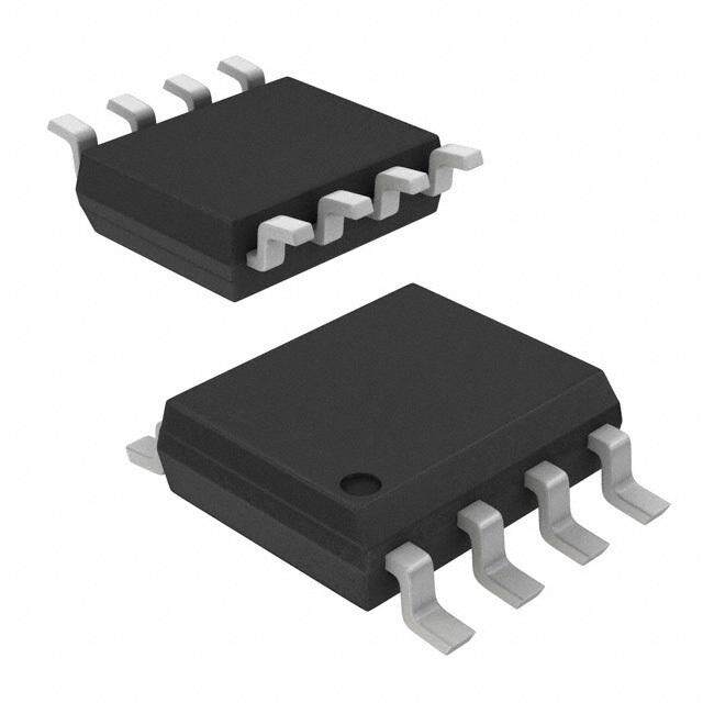
ICGOO电子元器件商城为您提供LT1026CN8#PBF由LINEAR TECHNOLOGY设计生产,在icgoo商城现货销售,并且可以通过原厂、代理商等渠道进行代购。 LT1026CN8#PBF价格参考。LINEAR TECHNOLOGYLT1026CN8#PBF封装/规格:PMIC - 稳压器 - DC DC 开关稳压器, 固定 充电泵 开关稳压器 IC 正或负 -Vin,2Vin 2 输出 15mA 8-DIP(0.300",7.62mm)。您可以下载LT1026CN8#PBF参考资料、Datasheet数据手册功能说明书,资料中有LT1026CN8#PBF 详细功能的应用电路图电压和使用方法及教程。
| 参数 | 数值 |
| 产品目录 | 集成电路 (IC) |
| 描述 | IC REG SWITCHED CAP DBL INV 8DIP |
| 产品分类 | |
| 品牌 | Linear Technology |
| 数据手册 | http://www.linear.com/docs/2572 |
| 产品图片 |
|
| 产品型号 | LT1026CN8#PBF |
| PWM类型 | - |
| rohs | 无铅 / 符合限制有害物质指令(RoHS)规范要求 |
| 产品系列 | - |
| 产品目录页面 | |
| 供应商器件封装 | 8-PDIP |
| 其它名称 | LT1026CN8PBF |
| 包装 | 管件 |
| 同步整流器 | 无 |
| 安装类型 | 通孔 |
| 封装/外壳 | 8-DIP(0.300",7.62mm) |
| 工作温度 | 0°C ~ 70°C |
| 标准包装 | 50 |
| 电压-输入 | 4 V ~ 10 V |
| 电压-输出 | ±7 V ~ ±18 V |
| 电流-输出 | 15mA |
| 类型 | 切换式电容器(充电泵),倍增器,反相 |
| 输出数 | 1 |
| 输出类型 | 可调式 |
| 频率-开关 | - |


PDF Datasheet 数据手册内容提取
LT1026 Voltage Converter FEATURES DESCRIPTIOU n Generates + and – from Single Input The LT®1026 is a switched capacitor voltage doubler and n Up to – 18V Output inverter on a single monolithic die. Capable of operating n m F Capacitors from a 4V to 10V input, it provides – 7V to – 18V output. n No Inductors Output currents of over 10mA are available. Two charge n 10mA Output Current Minimum pumps first double the input voltage then invert the n Operates Down to 4V doubled voltage. Manufactured in bipolar technology, the n No Latchup LT1026 is not susceptible to latchup and generates up to n 8-Pin Minidip 36V. The LT1026 offers a convenient way of generating addi- APPLICATIOU S tional system voltages without using inductors. Powering interface circuits, op amps or data acquisition circuitry off n Line Drivers logic supplies is simplified. n Op Amp Suppliers n Battery Splitters , LTC and LT are registered trademarks of Linear Technology Corporation. n RS232 Power TYPICAL APPLICATIOU Voltage Doubler and Inverter Output Voltage C1 10 1µF 8 C = 1µF + VIN = 5V 6 TA = 25°C 1 C1– +VOUT 8 + +VOUT AGE (V) 42 + 2 C2+ C1+ 7 1µF OLT 0 1Cµ2F 3 C2– LT1026 VIN 6 VIN TPUT V –2 U –4 –VOUT 4 –VOUT GND 5 O –6 1µF –8 + –10 1026 • TA01 0 5 10 15 20 25 LOAD CURRENT (mA) LT1026 • TA02 1026fb 1
LT1026 ABSOLUTE WMAXIWMUWM RATIUNGS (Note 1) Supply Voltage ........................................................10V Operating Temperature Range V+............................................................................20V LT1026C................................................. 0(cid:176) C to 70(cid:176) C V–..........................................................................–20V LT1026I..............................................–40(cid:176) C to 85(cid:176) C Short-Circuit Duration .........................................10 sec LT1026M (OBSOLETE)............... –55(cid:176) C to 125(cid:176) C Lead Temperature (Soldering, 10 sec)................. 300(cid:176) C PACKAGE/ORDER INUFORWMATIONU TOP VIEW TOP VIEW +VOUT TOP VIEW C1– 1 8 7 C1+ C1– 1 8 +VOUT C1– 1 8 +VOUT C2+ 2 7 C1+ C2+ 2 7 C1+ C2+ 2 6 VIN C2– 3 6 VIN C2– 3 6 VIN C2– 3 5 GND –VOUT 4 5 GND –VOUT 4 5 GND 4 –VOUT J8 PACKAGE N8 PACKAGE S8 PACKAGE 8-LEAD PDIP 8-LEAD PLASTIC SO H PACKAGE 8-LEAD CERDIP TJ8M-ALXE A= D1 5T0O(cid:176)-C5, qMJEA T=A 1L5 C0(cid:176)ACN/W TJMAX = 150(cid:176)C, q JA = 150(cid:176)C/W TTJJMMAAXX == 115500(cid:176)(cid:176)CC,, qq JJAA == 110500(cid:176)(cid:176)CC//WW ((NS88)) ORDER PART ORDER PART ORDER PART S8 PART NUMBER NUMBER NUMBER MARKING LT1026CH LT1026CJ8 LT1026CN8 1026 LT1026MH LT1026MJ8 LT1026CS8 1026I OBSOLETE PACKAGES LT1026IS8 Consider the N8 or S8 Packages for Alternate Source Consult LTC Marketing for parts specified with wider operating temperature ranges. ELECTRICAL CHARACTERISTICS The l denotes the specifications which apply over the full operating temperature range, otherwise specifications are at T = 25(cid:176) C. A PARAMETERS CONDITIONS MIN TYP MAX UNITS Output Voltage V = 4V I = 0mA Positive l 6.5 7 V IN L (Note 2) I = 0mA Negative l –6 –6.7 V L I = 10mA Positive l 5.25 5.7 V L I = –10mA Negative l –4.5 –5 V L V = 5V I = 15mA Positive l 6.25 7 V IN L I = –15mA Negative l –5.5 –6.2 V L V = 10V I = 0mA Positive l 18 18.5 V IN L I = 0mA Negative l –17.7 –18 V L I = 10mA Positive l 16 17.6 V L I = –10mA Negative l –15.3 –17 V L I = 15mA Positive l 15.25 17 V L I = –15mA Negative l –14.5 –16.5 V L V = 5V I = 10mA, –10mA Positive l 6.25 7.2 V IN L Negative l –5.5 –6.5 V V = 10V I = 10mA, –10mA Positive l 15 16.8 V IN L Negative l –14.25 –15.75 V 1026fb 2
LT1026 ELECTRICAL CHARACTERISTICS The l denotes the specifications which apply over the full operating temperature range, otherwise specifications are at T = 25(cid:176) C. A PARAMETERS CONDITIONS MIN TYP MAX UNITS Supply Current V = 4V I = 0mA l 7 12.5 mA IN L V = 10V I = 0mA l 15 30 mA IN L Note 1: Absolute Maximum Ratings are those values beyond which the life of a device may be impaired. Note 2: V min = –4.5 for T £ 40(cid:176) C IN A TYPICAL PERFORWMAUNCE CHARACTERISTICS Load Regulation (Both Outputs Load Regulation for Positive Load Regulation for Negative Loaded) Loading Loading 10 10 10 8 CV IN= 1=µ 5FV 8 8 IL = 0 6 TA = 25°C 6 6 V) 4 V) 4 V) 4 E ( E ( E ( AG 2 AG 2 C = 1µF AG 2 C = 1µF T T T OL 0 OL 0 VIN = 5V OL 0 VIN = 5V T V T V TA = 25°C T V TA = 25°C U –2 U –2 U –2 P P P T T T U –4 U –4 U –4 O O O –6 –6 –6 IL = 0 –8 –8 –8 –10 –10 –10 0 5 10 15 20 25 0 5 10 15 20 25 0 5 10 15 20 25 LOAD CURRENT (mA) LOAD CURRENT (mA) LOAD CURRENT (mA) LT1026 • TPC01 LT1026 • TPC02 LT1026 • TPC03 Supply Current Supply Current Supply Current 90 60 60 C = 22µF C = 22µF C = 22µF 75 VIN = 5V 50 VIN = 5V 50 VIN = 5V TA = 25°C TA = 25°C TA = 25°C A) BOTH OUTPUTS A) NEGATIVE A) POSITIVE T (m 60 LOADED T (m 40 OLOUATDPUEDT T (m 40 OLOUATDPUEDT N N N E E E R R R R 45 R 30 R 30 U U U C C C Y Y Y L L L P 30 P 20 P 20 P P P U U U S S S 15 10 10 0 0 0 0 5 10 15 20 25 0 5 10 15 20 25 0 5 10 15 20 25 OUTPUT CURRENT (mA) OUTPUT CURRENT (mA) OUTPUT CURRENT (mA) LT1026 • TPC04 LT1026 • TPC05 LT1026 • TPC06 1026fb 3
LT1026 TYPICAL PERFORWMAUNCE CHARACTERISTICS Ripple Output Voltage vs Temperature 60 10 VIN = 5V 8 50 IL = 5mV BOTH OUTPUTS 6 V) 4 RIPPLE (mV)P-P 234000 TPUT VOLTAGE ( –202 CVIL I N== 2=12 m5µVAF U –4 O –6 10 –8 0 –10 1.0 2.2 4.7 10 22 47 100 –50 –25 0 25 50 75 100 125 OUTPUT CAPACITOR (µF) TEMPERATURE (°C) 1026 • TPC07 LT1026 • TPC08 APPLICATIOUNS INUFORWMATIOUN The LT1026 is a nonregulating voltage converter that The substrate diodes are an inherent part of the IC, and converts a single input voltage into both a positive and must always be reversed biased to isolate the individual negative output at up to 15mA. A positive input voltage is transistors. In the LT1026 the substrate is tied to the first doubled and then the doubled voltage is inverted. The negative output. If the negative output is not used, such as voltage output level is dependent on both the input voltage when only the voltage doubler output is needed, –V OUT and the output loading. The total output current available must be tied to ground so the substrate diodes are depends on the individual loading of the outputs since properly biased. The substrate diodes must never become loading on one output affects the load and the voltage of forward biased even during overload conditions. For ex- the other. ample, pulling –V positive with respect to ground can OUT forward bias the substrate diodes. Clamping the substrate Only four external components are needed for operation. to ground with an external diode would be needed to Two charge pump capacitors and two output storage ensure proper operation and prevent the substrate from capacitors. Nominal value for these capacitors is 1m F, but carrying any current. the LT1026 will operate (with reduced performance) down to 0.1m F. Higher value capacitors (22m F) will reduce ripple No overload protection is included on the LT1026. Neither and slightly lower output impedance. For higher output output is damaged by momentary shorts, but during currents the outputs of several converters may be paral- sustained shorts the resulting high current flow will over- leled with common output capacitors. heat the IC. 1026fb 4
LT1026 TYPICAL APPLICATIOUNS Positive to Negative Converter Voltage Doubler 1 8 1µF NC C1– +VOUT NC + 2 7 + C2+ C1+ 1µF 3 C2– LT1026 VIN 6 VIN 1 C1– +VOUT 8 + VOUT –VOUT 4 –VOUT GND 5 2 C2+ C1+ 7 1µF LT1026 1µF 3 C2– VIN 6 VIN + 4 5 1026 • TA03 –VOUT GND 1026 • TA04 Standard Configuration Voltage Doubler and Inverter Voltage Quadrupler C1 C1 1µF 1µF + + 1 8 1 8 C1– +VOUT +VOUT C1– +VOUT +VOUT + + 2 7 2 7 + C2+ C1+ 1µF + C2+ C1+ 1µF C2 LT1026 C2 LT1026 1µF 3 C2– VIN 6 VIN 1µF 3 C2– VIN 6 –VOUT 4 –VOUT GND 5 4 –VOUT GND 5 VIN (FLOATING) 1µF + + 1026 • TA05 1µF 1026 • TA06 Parallel Converters for Higher Output Current and Lower Output Impedance C1 C1 1µF 1µF + + 1 8 1 8 C1– +VOUT C1– +VOUT +VOUT + 2 7 2 7 + C2+ C1+ + C2+ C1+ 1µF C2 LT1026 C2 LT1026 1µF 3 C2– VIN 6 VIN 1µF 3 C2– VIN 6 VIN 4 5 4 5 –VOUT GND –VOUT GND 1026 • TA07 1µF –VOUT + 1026fb 5
LT1026 TYPICAL APPLICATIOUNS 5V Powered RS232 Line Driver C1 1µF + 1 8 C1– +VOUT + 2 7 + C2+ C1+ 1µF LT1030 LT1026 3 C2– VIN 6 5VIN 4 5 –VOUT GND LOGIC LINE + 1026 • TA08 PACKAGE DESCRIPTIONU H Package 8-Lead TO-5 Metal Can (.230 Inch PCD) (Reference LTC DWG # 05-08-1321) .335 – .370 (8.509 – 9.398) DIA .027 – .045 .305 – .335 (0.686 – 1.143) (7.747 – 8.509) 45°TYP .040 PIN 1 .028 – .034 (1.016) .050 MAX (1.270) .165 – .185 (0.711 – 0.864) MAX (4.191 – 4.699) .230 REFERENCE (5.842) SEATING GAUGE PLANE TYP PLANE PLANE .500 – .750 (12.700 – 19.050) .010 – .045* H8 (TO-5) 0.230 PCD 0801 (0.254 – 1.143) .110 – .160 .016 – .021** (2.794 – 4.064) INSULATING (0.406 – 0.533) STANDOFF *LEAD DIAMETER IS UNCONTROLLED BETWEEN THE REFERENCE PLANE AND THE SEATING PLANE .016 – .024 **FOR SOLDER DIP LEAD FINISH, LEAD DIAMETER IS (0.406 – 0.610) OBSOLETE PACKAGE 1026fb 6
LT1026 PACKAGE DESCRIPTIONU J8 Package 8-Lead CERDIP (Narrow .300 Inch, Hermetic) (Reference LTC DWG # 05-08-1110) .405 (10.287) .300 BSC CORNER LEADS OPTION (5.2.00800) (0.0.10257) MAX (7.62 BSC) (4 PLCS) MAX MIN 8 7 6 5 .015 – .060 .023 – .045 (0.381 – 1.524) .025 .220 – .310 (0.584 – 1.143) HALF LEAD (0.635) (5.588 – 7.874) RAD TYP .008 – .018 0° – 15° OPTION (0.203 – 0.457) .045 – .068 (1.143 – 1.650) 1 2 3 4 J8 0801 FULL LEAD .045 – .065 OPTION .125 (1.143 – 1.651) NOTE: LEAD DIMENSIONS APPLY TO SOLDER DIP/PLATE 3.175 OR TIN PLATE LEADS .014 – .026 .100 MIN (0.360 – 0.660) (2.54) BSC OBSOLETE PACKAGE N8 Package 8-Lead PDIP (Narrow .300 Inch) (Reference LTC DWG # 05-08-1510) .400* (10.160) .300 – .325 .045 – .065 .130 – .005 MAX (7.620 – 8.255) (1.143 – 1.651) (3.302 – 0.127) 8 7 6 5 .065 .255 – .015* (1.651) .008 – .015 TYP (6.477 – 0.381) (0.203 – 0.381) .120 (3.048) .020 (8..322555–++–00..00..8331885591) (2.1.5004) (0..405178 –– 0.0M.00I73N6) (0M.5I0N8) 1 2 3 4N8 1002 BSC NOTE: INCHES 1. DIMENSIONS ARE MILLIMETERS *THESE DIMENSIONS DO NOT INCLUDE MOLD FLASH OR PROTRUSIONS. MOLD FLASH OR PROTRUSIONS SHALL NOT EXCEED .010 INCH (0.254mm) S8 Package 8-Lead Plastic Small Outline (Narrow 0.150) (LTC DWG # 05-08-1610) .189 – .197 (4.801 – 5.004) NOTE 3 .045 – .005 .010 – .020 · 45(cid:176) .053 – .069 .004 – .010 8 7 6 5 .050 BSC (0.254 – 0.508) (1.346 – 1.752) (0.101 – 0.254) .008 – .010 (0.203 – 0.254) 0°– 8° TYP (0..040166 –– .10.52700) .014 – .019 .050 (5..272981 –– .62.41497) (3..1851N00O T––E .3 13.59788) .M24IN5 .160 – .005 (0.355 – 0.483) (1.270) NOTE: INCHES TYP BSC 1. DIMENSIONS IN (MILLIMETERS) 2. DRAWING NOT TO SCALE .030 – .005 SO8 0303 3. THESE DIMENSIONS DO NOT INCLUDE MOLD FLASH OR PROTRUSIONS. 1 2 3 4 TYP MOLD FLASH OR PROTRUSIONS SHALL NOT EXCEED .006" (0.15mm) RECOMMENDED SOLDER PAD LAYOUT 1026fb Information furnished by Linear Technology Corporation is believed to be accurate and reliable. 7 However, no responsibility is assumed for its use. Linear Technology Corporation makes no represen- tation that the interconnection of its circuits as described herein will not infringe on existing patent rights.
LT1026 TYPICAL APPLICATIOUN Regulated Converter C1 1µF + 1 8 C1– +VOUT +VOUT + 9 3 2 7 1Cµ2F + 3 CC22+– LT1026 CV1IN+ 6 VIN ‡ 4V 1µF 8 INPUT– GND VIN OUT 2 5V 500k 0.001µF 4 –VOUT GND 5 5 COMP/PNP LT1020 FB 11 +10µF 1µF INPUT+ REFOUT COMP/NPN 500k + 7 4 6 + 0.001µF 10µF 1M 500k 500k –5V REG 10mA 1026 • TA09 2N3904 51k RELATED PARTS PART NUMBER DESCRIPTION COMMENTS LT1044 Switched Capacitor Voltage Converter Can be Used as Inverter/Doubler/Divider or a Multiplier, V = 1.5V to 9V, I = 60m A, SO-8 IN Q LT1054/LT1054L Switched Capacitors Voltage Converters with Regulator I to 100mA/125mA, V = 3.5V to 15V, Inverter, OUT IN Neg/Pos Doubler LTC1517-5 Micropower, Regulated 5V In SOT-23 Ultralow Power: I = 6m A Typical, Small 5-Pin SOT-23 CC LTC1550/LTC1551 Low Noise, Switched Capacitor Regulator Voltage Inverter < 1mVp-p Typical Output Ripple, 900kHz, I = 10mA OUT LTC1555/LTC1556 SIM Power Supply and Level Translator Step-Up/Step-Down Generates 5V, Input Voltage Range: 2.7V to 10V, > 10kV ESD, Short-Circuit and Overtemp Protection 1026fb 8 Linear Technology Corporation LT/TP 0203 REV B 1K • PRINTED IN USA 1630 McCarthy Blvd., Milpitas, CA 95035-7417 (408) 432-1900 l FAX: (408) 434-0507 l w ww.linear-tech.com ª LINEAR TECHNOLOGY CORPORATION 1988