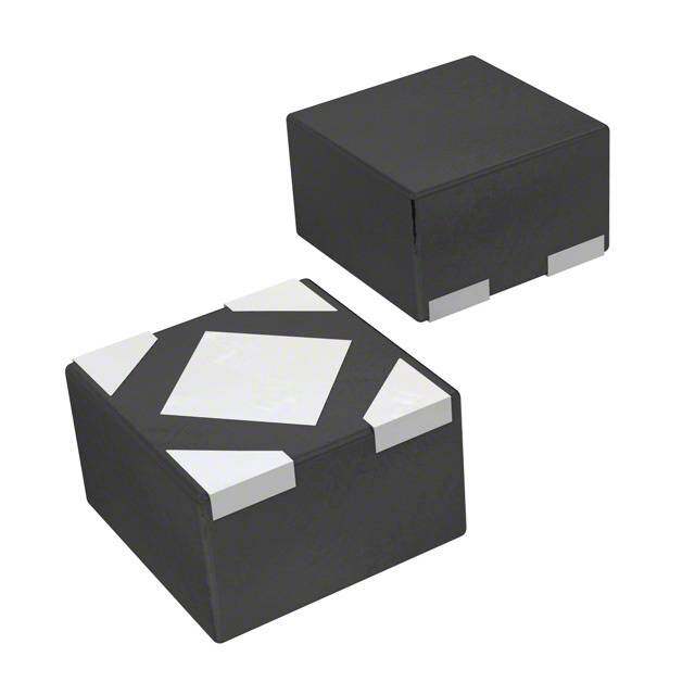
ICGOO在线商城 > 集成电路(IC) > PMIC - 稳压器 - 线性 > LP5907UVX-1.8/NOPB
- 型号: LP5907UVX-1.8/NOPB
- 制造商: Texas Instruments
- 库位|库存: xxxx|xxxx
- 要求:
| 数量阶梯 | 香港交货 | 国内含税 |
| +xxxx | $xxxx | ¥xxxx |
查看当月历史价格
查看今年历史价格
LP5907UVX-1.8/NOPB产品简介:
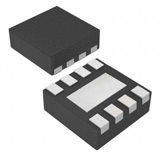
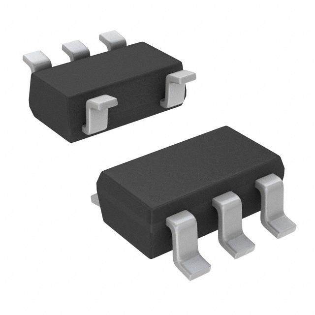
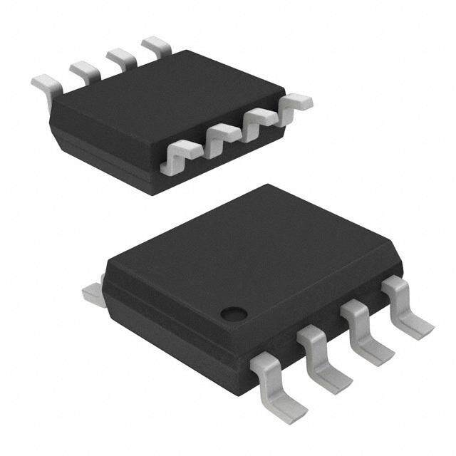
ICGOO电子元器件商城为您提供LP5907UVX-1.8/NOPB由Texas Instruments设计生产,在icgoo商城现货销售,并且可以通过原厂、代理商等渠道进行代购。 LP5907UVX-1.8/NOPB价格参考。Texas InstrumentsLP5907UVX-1.8/NOPB封装/规格:PMIC - 稳压器 - 线性, Linear Voltage Regulator IC Positive Fixed 1 Output 1.8V 250mA 4-DSBGA。您可以下载LP5907UVX-1.8/NOPB参考资料、Datasheet数据手册功能说明书,资料中有LP5907UVX-1.8/NOPB 详细功能的应用电路图电压和使用方法及教程。
LP5907UVX-1.8/NOPB 是 Texas Instruments(德州仪器)推出的一款低功耗、低压差线性稳压器(LDO),属于 PMIC(电源管理集成电路)中的线性稳压器类别。以下是该型号的主要应用场景:

 1. 便携式电子设备
   - LP5907UVX-1.8/NOPB 的低静态电流(典型值为 1.2 µA)和小封装(SOT-23-5)使其非常适合用于电池供电的便携式设备,例如:
     - 智能手表
     - 健康监测设备(如脉搏血氧仪、心率监测器)
     - 无线耳机(TWS 耳机)
     - 遥控器
   - 这些设备对电源效率和小型化设计要求较高,而 LP5907 的特性可以满足这些需求。

 2. 物联网(IoT)设备
   - 在 IoT 领域,LP5907 可以为低功耗传感器和无线模块提供稳定的电源支持,例如:
     - 温湿度传感器
     - 烟雾报警器
     - Zigbee 或 Bluetooth Low Energy(BLE)模块
   - 其 1.8V 固定输出电压适合为许多现代低功耗 MCU 和 RF 芯片供电。

 3. 消费类电子产品
   - 该稳压器适用于需要高效电源管理的消费类电子产品,例如:
     - 数码相机
     - MP3 播放器
     - 电子阅读器
   - LP5907 的低噪声特性有助于改善音频和显示性能。

 4. 工业应用
   - 在工业领域,LP5907 可用于需要长时间稳定运行的设备,例如:
     - 数据采集系统
     - 工业传感器
     - 可编程逻辑控制器(PLC)
   - 其宽输入电压范围(1.6V 至 5.5V)和高 PSRR(电源抑制比)特性,能够应对复杂的工业电源环境。

 5. 医疗设备
   - 对于便携式或手持式医疗设备,LP5907 的低功耗和高稳定性是理想选择,例如:
     - 血糖仪
     - 便携式超声设备
     - 家用健康监测设备

 总结
LP5907UVX-1.8/NOPB 凭借其低功耗、小尺寸和高稳定性,广泛应用于便携式电子设备、IoT 设备、消费类电子产品、工业设备以及医疗设备等领域。其 1.8V 输出电压特别适合为现代低功耗处理器、传感器和通信模块供电,同时其优异的性能指标确保了系统的可靠性和效率。
| 参数 | 数值 |
| 产品目录 | 集成电路 (IC)半导体 |
| 描述 | IC REG LDO 1.8V 0.25A 4DSBGA低压差稳压器 250mA,Ultra-Low Noise LDO Reg |
| 产品分类 | |
| 品牌 | Texas Instruments |
| 产品手册 | |
| 产品图片 |
|
| rohs | 符合RoHS无铅 / 符合限制有害物质指令(RoHS)规范要求 |
| 产品系列 | 电源管理 IC,低压差稳压器,Texas Instruments LP5907UVX-1.8/NOPB- |
| 数据手册 | |
| 产品型号 | LP5907UVX-1.8/NOPB |
| PCN组件/产地 | |
| PSRR/纹波抑制—典型值 | 82 dB |
| 产品 | LDO Regulators |
| 产品种类 | 低压差稳压器 |
| 供应商器件封装 | 4-DSBGA |
| 其它名称 | 296-35634-6 |
| 包装 | Digi-Reel® |
| 商标 | Texas Instruments |
| 回动电压—最大值 | 200 mV |
| 安装类型 | 表面贴装 |
| 安装风格 | SMD/SMT |
| 封装 | Reel |
| 封装/外壳 | 4-XFBGA,DSBGA |
| 封装/箱体 | DSBGA-4 |
| 工作温度 | -40°C ~ 85°C |
| 工厂包装数量 | 3000 |
| 最大工作温度 | + 125 C |
| 最大输入电压 | 5.5 V |
| 最小工作温度 | - 40 C |
| 最小输入电压 | 2.2 V |
| 标准包装 | 1 |
| 电压-跌落(典型值) | 0.12V @ 250mA |
| 电压-输入 | 2.2 V ~ 5.5 V |
| 电压-输出 | 1.8V |
| 电流-输出 | 250mA |
| 电流-限制(最小值) | - |
| 稳压器拓扑 | 正,固定式 |
| 稳压器数 | 1 |
| 类型 | Ultra Low Noise Linear Regulator |
| 系列 | LP5907 |
| 线路调整率 | 0.02 % |
| 设计资源 | http://www.digikey.com/product-highlights/cn/zh/texas-instruments-webench-design-center/3176 |
| 负载调节 | 0.001 % |
| 输出电压 | 1.8 V |
| 输出电压容差 | 2 % |
| 输出电流 | 250 mA |
| 输出端数量 | 1 Output |
| 输出类型 | Fixed |



PDF Datasheet 数据手册内容提取
Product Order Technical Tools & Support & Reference Folder Now Documents Software Community Design LP5907 SNVS798O–APRIL2012–REVISEDJUNE2020 LP5907 250-mA, Ultra-Low-Noise, Low-I LDO Q 1 Features 3 Description • Inputvoltagerange:2.2Vto5.5V The LP5907 is a low-noise LDO that can supply up to 1 250 mA output current. Designed to meet the • Outputvoltagerange:1.2Vto4.5V requirements of RF and analog circuits, the LP5907 • Stablewith1-µFceramicinputandoutput device provides low noise, high PSRR, low quiescent capacitors current, and low line or load transient response • Nonoisebypasscapacitorrequired figures. Using new innovative design techniques, the LP5907 offers class-leading noise performance • Remoteoutputcapacitorplacement without a noise bypass capacitor and the ability for • Thermal-overloadandshort-circuitprotection remoteoutputcapacitorplacement. • –40°Cto125°Coperatingjunctiontemperature The device is designed to work with a 1-µF input and • Lowoutputvoltagenoise:< 6.5 µVRMS a 1-µF output ceramic capacitor (no separate noise • PSRR:82dBat1kHz bypasscapacitorisrequired). • Outputvoltagetolerance:±2% This device is available with fixed output voltages • VerylowI (enabled):12µA from 1.2 V to 4.5 V in 25-mV steps. Contact Texas Q InstrumentsSalesforspecificvoltageoptionneeds. • Lowdropout:120mV(typical) • CreateacustomdesignusingtheLP5907with DeviceInformation(1) theWEBENCH®PowerDesigner PARTNUMBER PACKAGE BODYSIZE DSBGA(4) 0.645mm×0.645mm(NOM) 2 Applications LP5907 SOT-23(5) 2.90mm×1.60mm(NOM) • Smartphones X2SON(4) 1.00mm×1.00mm(NOM) • Tablets (1) For all available packages, see the orderable addendum at • Communicationsequipment theendofthedatasheet. • Digitalstillcameras space • Factoryautomation space space SimplifiedSchematic INPUT IN OUT OUTPUT 1 (cid:29)F 1 (cid:29)F LP5907 ENABLE EN GND GND 1 An IMPORTANT NOTICE at the end of this data sheet addresses availability, warranty, changes, use in safety-critical applications, intellectualpropertymattersandotherimportantdisclaimers.PRODUCTIONDATA.
LP5907 SNVS798O–APRIL2012–REVISEDJUNE2020 www.ti.com Table of Contents 1 Features.................................................................. 1 7.4 DeviceFunctionalModes........................................13 2 Applications........................................................... 1 8 ApplicationandImplementation........................ 14 3 Description............................................................. 1 8.1 ApplicationInformation............................................14 4 RevisionHistory..................................................... 2 8.2 TypicalApplication..................................................14 5 PinConfigurationandFunctions......................... 4 9 PowerSupplyRecommendations...................... 17 6 Specifications......................................................... 5 10 Layout................................................................... 18 6.1 AbsoluteMaximumRatings......................................5 10.1 LayoutGuidelines.................................................18 6.2 ESDRatings..............................................................5 10.2 LayoutExamples...................................................18 6.3 RecommendedOperatingConditions.......................5 11 DeviceandDocumentationSupport................. 20 6.4 ThermalInformation..................................................6 11.1 DocumentationSupport........................................20 6.5 ElectricalCharacteristics...........................................6 11.2 ReceivingNotificationofDocumentationUpdates20 6.6 OutputandInputCapacitors.....................................7 11.3 SupportResources...............................................20 6.7 TypicalCharacteristics..............................................8 11.4 Trademarks...........................................................20 7 DetailedDescription............................................ 12 11.5 ElectrostaticDischargeCaution............................20 7.1 Overview.................................................................12 11.6 Glossary................................................................20 7.2 FunctionalBlockDiagram.......................................12 12 Mechanical,Packaging,andOrderable Information........................................................... 21 7.3 FeatureDescription.................................................12 4 Revision History NOTE:Pagenumbersforpreviousrevisionsmaydifferfrompagenumbersinthecurrentversion. ChangesfromRevisionN(April2018)toRevisionO Page • ChangedApplicationssection................................................................................................................................................ 1 • ChangedDSBGAbodysizeinDeviceInformationtable ...................................................................................................... 1 • AddedYKGtopinoutcaptionofPinConfigurationandFunctionssection............................................................................ 4 • AddedYKGcolumntoThermalInformationtable.................................................................................................................. 6 ChangesfromRevisionM(January2018)toRevisionN Page • AddedOvershootonstart-upwithENrowtoElectricalCharacteristicstable ...................................................................... 7 ChangesfromRevisionL(August2016)toRevisionM Page • AddedlinksforWEBENCH ................................................................................................................................................... 1 • AddedinformationaboutYKMpackageoption ..................................................................................................................... 1 • Addedminoreditorialchanges .............................................................................................................................................. 1 ChangesfromRevisionK(May2016)toRevisionL Page • ChangedtitleofdatasheetandupdatedlistofApplicationsandwordingof1stsentenceinDescription............................ 1 • Changed"10µV "to"6.5µV "....................................................................................................................................... 1 RMS RMS ChangesfromRevisionJ(March2016)toRevisionK Page • Changed"LinearRegulator"to"LDO"intitleandfirstsentenceofDescription.................................................................... 1 2 SubmitDocumentationFeedback Copyright©2012–2020,TexasInstrumentsIncorporated ProductFolderLinks:LP5907
LP5907 www.ti.com SNVS798O–APRIL2012–REVISEDJUNE2020 ChangesfromRevisionI(August2015)toRevisionJ Page • ChangedV minandmaxvaluesandV minvalueinAbsMaxtableandV rowofROCtabletocorrectformat OUT EN EN errors;replacetextoffootnote2ofAbsMaxtable ............................................................................................................... 5 ChangesfromRevisionH(November2014)toRevisionI Page • AddediconforreferencedesigntoTopNavsand"ΔV vsTemperature"graphtoTypicalCharacteristics.....................1 OUT • ChangedStorageTemperaturetoAbsMaxtable;replaceHandlingRatingswithESDRatings ......................................... 5 • Deleted"V ≥1.8V"fromfirstrowofΔVoutspec ............................................................................................................. 6 OUT • Added"SOT-23,X2SONpackages"tosecondrowofΔVoutspec ...................................................................................... 6 ChangesfromRevisionG(October2013)toRevisionH Page • AddedDeviceInformationandHandlingRatingtables,FeatureDescription,DeviceFunctionalModes,Application andImplementation,PowerSupplyRecommendations,Layout,DeviceandDocumentationSupport,and Mechanical,Packaging,andOrderableInformationsections;movedsomecurvestoApplicationCurvessection .............1 Copyright©2012–2020,TexasInstrumentsIncorporated SubmitDocumentationFeedback 3 ProductFolderLinks:LP5907
LP5907 SNVS798O–APRIL2012–REVISEDJUNE2020 www.ti.com 5 Pin Configuration and Functions YKE,YKG,andYKMPackages 4-PinDSBGA IN OUT OUT IN A1 A2 A2 A1 B1 B2 B2 B1 EN GND GND EN TOP VIEW BOTTOM VIEW PinFunctions:DSBGA PIN DSBGA I/O DESCRIPTION NAME NUMBER A1 IN I Inputvoltagesupply.Connecta1-µFcapacitoratthisinput. Regulatedoutputvoltage.Connectaminimum1-µFlow-ESRcapacitortothispin.Connect A2 OUT O thisoutputtotheloadcircuit.Aninternal230-Ω(typical)pulldownresistorpreventsacharge remainingonV whentheregulatorisintheshutdownmode(V low). OUT EN Enableinput.Alowvoltage(<V )onthispinturnstheregulatoroffanddischargesthe IL outputpintoGNDthroughaninternal230-Ωpulldownresistor.Ahighvoltage(>V )onthis B1 EN I IH pinenablestheregulatoroutput.Thispinhasaninternal1-MΩpulldownresistortoholdthe regulatoroffbydefault. B2 GND — Commonground DQNPackage DBVPackage 4-PinX2SON 5-PinSOT-23 BottomView TopView OUT GND 1 2 IN 1 5 OUT GND 2 5 EN 3 4 N/C 4 3 IN EN PinFunctions:X2SON,SOT-23 PIN X2SON SOT-23 I/O DESCRIPTION NAME NUMBER NUMBER IN 4 1 I Inputvoltagesupply.Connecta1-µFcapacitoratthisinput. Regulatedoutputvoltage.Connectaminimum1-µFlow-ESRcapacitortothis pin.Connectthisoutputtotheloadcircuit.Aninternal230-Ω(typical)pulldown OUT 1 5 O resistorpreventsachargeremainingonV whentheregulatorisinthe OUT shutdownmode(V low). EN Enableinput.Alowvoltage(<V )onthispinturnstheregulatoroffand IL dischargestheoutputpintoGNDthroughaninternal230-Ωpulldownresistor.A EN 3 3 I highvoltage(>V )onthispinenablestheregulatoroutput.Thispinhasan IH internal1-MΩpulldownresistortoholdtheregulatoroffbydefault. GND 2 2 — Commonground N/C — 4 — Nointernalelectricalconnection. ThermalpadforX2SONpackage,connecttoGNDorleavefloating.Donot ThermalPad 5 — — connecttoanypotentialotherthanGND. 4 SubmitDocumentationFeedback Copyright©2012–2020,TexasInstrumentsIncorporated ProductFolderLinks:LP5907
LP5907 www.ti.com SNVS798O–APRIL2012–REVISEDJUNE2020 6 Specifications 6.1 Absolute Maximum Ratings overoperatingfree-airtemperaturerange(unlessotherwisenoted)(1)(2) MIN MAX UNIT V Inputvoltage –0.3 6 IN V Outputvoltage –0.3 See(3) V OUT V Enableinputvoltage –0.3 6 EN Continuouspowerdissipation(4) InternallyLimited W T Junctiontemperature 150 °C JMAX T Storagetemperature –65 150 °C stg (1) StressesbeyondthoselistedunderAbsoluteMaximumRatingsmaycausepermanentdamagetothedevice.Thesearestressratings only,andfunctionaloperationofthedeviceattheseoranyotherconditionsbeyondthoseindicatedunderRecommendedOperating Conditionsisnotimplied.Exposuretoabsolute-maximum-ratedconditionsforextendedperiodsmayaffectdevicereliability. (2) AllvoltagesarewithrespecttotheGNDpin. (3) AbsMaxV isthelessorofV +0.3V,or6V. OUT IN (4) Internalthermalshutdowncircuitryprotectsthedevicefrompermanentdamage. 6.2 ESD Ratings VALUE UNIT Human-bodymodel(HBM),perANSI/ESDA/JEDECJS-001(1) ±2000 V Electrostaticdischarge V (ESD) Charged-devicemodel(CDM),perJEDECspecificationJESD22-C101(2) ±1000 (1) JEDECdocumentJEP155statesthat500-VHBMallowssafemanufacturingwithastandardESDcontrolprocess. (2) JEDECdocumentJEP157statesthat250-VCDMallowssafemanufacturingwithastandardESDcontrolprocess. 6.3 Recommended Operating Conditions overoperatingfree-airtemperaturerange(unlessotherwisenoted)(1)(2) MIN MAX UNIT V Inputsupplyvoltage 2.2 5.5 IN V V Enableinputvoltage 0 5.5 EN I Outputcurrent 0 250 mA OUT T Junctiontemperature –40 125 °C J T Ambienttemperature(3) –40 85 °C A (1) StressesbeyondthoselistedunderAbsoluteMaximumRatingsmaycausepermanentdamagetothedevice.Thesearestressratings only,andfunctionaloperationofthedeviceattheseoranyotherconditionsbeyondthoseindicatedunderRecommendedOperating Conditionsisnotimplied.Exposuretoabsolute-maximum-ratedconditionsforextendedperiodsmayaffectdevicereliability. (2) AllvoltagesarewithrespecttotheGNDpin. (3) Inapplicationswherehighpowerdissipationand/orpoorpackagethermalresistanceispresent,themaximumambienttemperaturemay havetobederated.Maximumambienttemperature(T )isdependentonthemaximumoperatingjunctiontemperature(T = A-MAX J-MAX-OP 125°C),themaximumpowerdissipationofthedeviceintheapplication(P ),andthejunction-toambientthermalresistanceofthe D-MAX part/packageintheapplication(R ),asgivenbythefollowingequation:T =T –(R ×P ).SeeApplicationand θJA A-MAX J-MAX-OP θJA D-MAX Implementation. Copyright©2012–2020,TexasInstrumentsIncorporated SubmitDocumentationFeedback 5 ProductFolderLinks:LP5907
LP5907 SNVS798O–APRIL2012–REVISEDJUNE2020 www.ti.com 6.4 Thermal Information LP5907 THERMALMETRIC(1) DBV DQN YKE YKG YKM UNIT (SOT-23) (X2SON) (DSBGA) (DSBGA) (DSBGA) 5PINS 4PINS 4PINS 4PINS 4PINS R Junction-to-ambientthermalresistance 193.4 216.1 206.1 191.6 194.1 °C/W θJA R Junction-to-case(top)thermalresistance 102.1 161.7 1.5 2.4 3.0 °C/W θJC(top) R Junction-to-boardthermalresistance 45.8 162.1 37.0 58.9 62.7 °C/W θJB ψ Junction-to-topcharacterizationparameter 8.4 5.1 15.0 1.1 1.1 °C/W JT ψ Junction-to-boardcharacterizationparameter 45.3 161.7 36.8 58.9 62.7 °C/W JB R Junction-to-case(bottom)thermalresistance n/a 123.0 n/a n/a n/a °C/W θJC(bot) (1) Formoreinformationabouttraditionalandnewthermalmetrics,seetheSemiconductorandICPackageThermalMetricsapplication report. 6.5 Electrical Characteristics V =V +1V,V =1.2V,I =1mA,C =1µF,C =1µF(unlessotherwisenoted)(1)(2)(3) IN OUT(NOM) EN OUT IN OUT PARAMETER TESTCONDITIONS MIN TYP MAX UNIT V Inputvoltage T =25°C 2.2 5.5 V IN A V =(V +1V)to5.5V, IN OUT(NOM) –2 2 I =1mAto250mA OUT Outputvoltagetolerance VIN=(VOUT(NOM)+1V)to5.5V, %VOUT I =1mAto250mA –3 3 OUT ΔVOUT (VOUT<1.8V,SOT-23,X2SONpackages) V =(V +1V)to5.5V, Lineregulation IN OUT(NOM) 0.02 %/V I =1mA OUT Loadregulation I =1mAto250mA 0.001 %/mA OUT Loadcurrent See(4) 0 250 mA I LOAD Maximumoutputcurrent 250 V =1.2V,I =0mA 12 25 EN OUT I Quiescentcurrent(5) V =1.2V,I =250mA 250 425 µA Q EN OUT V =0.3V(disabled) 0.2 1 EN I Groundcurrent(6) V =1.2V,I =0mA 14 µA G EN OUT I =100mA 50 OUT V Dropoutvoltage(7) I =250mA(DSBGApackage) 120 200 mV DO OUT I =250mA(SOT-23,X2SONpackages) 250 OUT I Short-circuitcurrentlimit T =25°C(8) 250 500 mA SC A (1) AllvoltagesarewithrespecttothedeviceGNDterminal,unlessotherwisestated. (2) Minimumandmaximumlimitsareensuredthroughtest,design,orstatisticalcorrelationoverthejunctiontemperature(T)rangeof J –40°Cto125°C,unlessotherwisestated.TypicalvaluesrepresentthemostlikelyparametricnormatT =25°C,andareprovidedfor A referencepurposesonly. (3) Inapplicationswherehighpowerdissipationand/orpoorpackagethermalresistanceispresent,themaximumambienttemperaturemay havetobederated.Maximumambienttemperature(T )isdependentonthemaximumoperatingjunctiontemperature(T = A-MAX J-MAX-OP 125°C),themaximumpowerdissipationofthedeviceintheapplication(P ),andthejunction-toambientthermalresistanceofthe D-MAX part/packageintheapplicationR ),asgivenbythefollowingequation:T =T –(R ×P ).SeeApplicationand θJA A-MAX J-MAX-OP θJA D-MAX Implementation. (4) Thedevicemaintainsastable,regulatedoutputvoltagewithoutaloadcurrent. (5) QuiescentcurrentisdefinedhereasthedifferenceincurrentbetweentheinputvoltagesourceandtheloadatV . OUT (6) Groundcurrentisdefinedhereasthetotalcurrentflowingtogroundasaresultofallinputvoltagesappliedtothedevice. (7) Dropoutvoltageisthevoltagedifferencebetweentheinputandtheoutputatwhichtheoutputvoltagedropsto100mVbelowits nominalvalue. (8) Short-circuitcurrent(I )fortheLP5907isequivalenttocurrentlimit.Tominimizethermaleffectsduringtesting,I ismeasuredwith SC SC V pulledto100mVbelowitsnominalvoltage. OUT 6 SubmitDocumentationFeedback Copyright©2012–2020,TexasInstrumentsIncorporated ProductFolderLinks:LP5907
LP5907 www.ti.com SNVS798O–APRIL2012–REVISEDJUNE2020 Electrical Characteristics (continued) V =V +1V,V =1.2V,I =1mA,C =1µF,C =1µF(unlessotherwisenoted)(1)(2)(3) IN OUT(NOM) EN OUT IN OUT PARAMETER TESTCONDITIONS MIN TYP MAX UNIT f=100Hz,I =20mA 90 OUT f=1kHz,I =20mA 82 PSRR Power-supplyrejectionratio(9) OUT dB f=10kHz,I =20mA 65 OUT f=100kHz,I =20mA 60 OUT I =1mA 10 e Outputnoisevoltage(9) BW=10Hzto100kHz OUT µV N RMS I =250mA 6.5 OUT Outputautomaticdischarge R V <V (outputdisabled) 230 Ω AD pulldownresistance EN IL Thermalshutdown T rising 160 J T °C SD Thermalhysteresis T fallingfromshutdown 15 J LOGICINPUTTHRESHOLDS V =2.2Vto5.5V, V Lowinputthreshold IN 0.4 V IL V fallinguntiltheoutputisdisabled EN V =2.2Vto5.5V V Highinputthreshold IN 1.2 V IH V risinguntiltheoutputisenabled EN V =5.5VandV =5.5V 5.5 I InputcurrentatENpin(10) EN IN µA EN V =0VandV =5.5V 0.001 EN IN TRANSIENTCHARACTERISTICS V =(V +1V)to IN OUT(NOM) –1 (V )+1.6V)in30µs Linetransient(9) OUT(NOM V =(V +1.6V)to (VIN OU)T(+NO1M.6)V)in30µs 1 mV OUT(NOM I =1mAto250mAin10µs –40 Loadtransient(9) OUT ΔVOUT IOUT=250mAto1mAin10µs 40 Overshootonstart-up(9) StatedasapercentageofV 5% OUT(NOM) StatedasapercentageofV ,V = OUT(NOM) IN Overshootonstart-upwithEN(9) VOUT+1Vto5.5V,0.7µF<COUT<10µF, 1% 0mA<I <250mA,ENrisinguntilthe OUT outputisenabled FromV >V toV =95%ofV , t Turnontime EN IH OUT OUT(NOM) 80 150 µs ON T =25°C A (9) Thisspecificationisverifiedbydesign. (10) Thereisa1-MΩresistorbetweenENandgroundonthedevice. 6.6 Output and Input Capacitors overoperatingfree-airtemperaturerange(unlessotherwisenoted) PARAMETER TESTCONDITIONS MIN(1) TYP MAX UNIT C Inputcapacitance(2) 0.7 1 µF IN Capacitanceforstability C Outputcapacitance(2) 0.7 1 10 µF OUT ESR Output/Inputcapacitance(2) 5 500 mΩ (1) Theminimumcapacitanceshouldbegreaterthan0.5µFoverthefullrangeofoperatingconditions.Thecapacitortoleranceshouldbe 30%orbetteroverthefulltemperaturerange.Thefullrangeofoperatingconditionsforthecapacitorintheapplicationmustbe consideredduringdeviceselectiontoensurethisminimumcapacitancespecificationismet.X7Rcapacitorsarerecommendedhowever capacitortypesX5R,Y5VandZ5Umaybeusedwithconsiderationoftheapplicationandconditions. (2) Thisspecificationisverifiedbydesign. Copyright©2012–2020,TexasInstrumentsIncorporated SubmitDocumentationFeedback 7 ProductFolderLinks:LP5907
LP5907 SNVS798O–APRIL2012–REVISEDJUNE2020 www.ti.com 6.7 Typical Characteristics V =3.7V,V =2.8V,I =1mA,C =1µF,C =1µF,andT =25°C(unlessotherwisenoted) IN OUT OUT IN OUT A 16 1 14 0.9 12 10 (cid:29)(A)Q 8 N (V) 0.8 I E 6 V 0.7 4 0.6 2 VIH Rising 0 VIL Falling 0.5 2.3 2.8 3.3 3.8 4.3 4.8 5.3 5.8 2 2.5 3 3.5 4 4.5 5 5.5 6 VIN(V) VIN (V) SVA-30180569 D001 Figure1.QuiescentCurrentvsInputVoltage Figure2.VENThresholdsvsVIN 1.4 5 4.5 1.2 4 1 3.5 V) 0.8 V) 3 T ( T ( 2.5 U U O 0.6 O V V 2 0.4 1.5 1 0.2 RLOAD = 1.2 k: 0.5 RLOAD = 4.5 k: RLOAD = 4.8 : RLOAD = 18 : 0 0 0 0.5 1 1.5 2 2.5 0 1 2 3 4 5 6 VIN (V) VIN (V) D002 D003 V =1.2V,V =V V =4.5V,V =V OUT EN IN OUT EN IN Figure3.V vsV Figure4.V vsV OUT IN OUT IN 350 2.900 VIN= 3.6V 300 2.875 A) (cid:29)T ( 250 2.850 N RE 200 V)2.825 R (T U U2.800 ND C 150 VO2.775 GROU 100 VIN = 3.0V 2.750 -40°C 50 VIN = 3.8V 2.725 90°C VIN = 4.2V 25°C VIN = 5.5V 0 2.700 0 50 100 150 200 250 300 0 50 100 150 200 250 IOUT(mA) LOAD (mA) SVA-30180571 SVA-30180567 Figure5.GroundCurrentvsOutputCurrent Figure6.LoadRegulation 8 SubmitDocumentationFeedback Copyright©2012–2020,TexasInstrumentsIncorporated ProductFolderLinks:LP5907
LP5907 www.ti.com SNVS798O–APRIL2012–REVISEDJUNE2020 Typical Characteristics (continued) V =3.7V,V =2.8V,I =1mA,C =1µF,C =1µF,andT =25°C(unlessotherwisenoted) IN OUT OUT IN OUT A 0.2 2.900 2.875 Load = 10 mA 0.1 2.850 %) 0 (V)T2.825 (UT -0.1 OU2.800 O V V 2.775 ’ -0.2 2.750 -40°C 90°C -0.3 2.725 25°C 2.700 -0.4 3.0 3.5 4.0 4.5 5.0 5.5 -50 -25 0 25 50 75 100 125 Junction Temperature (qC) D010 VIN(V) SVA-30180568 Figure7.ΔV vsTemperature Figure8.LineRegulation OUT 2V/DIV VOUT VOUT 10 mV/ (AC Coupled) DIV 2V/DIV VIN = VEN VIN 1V/DIV IIN 1A/DIV 2 ms/DIV 10 (cid:29)s/DIV SVA-30180509 SVA-30180510 V =3.2V↔4.2V,load=1mA IN Figure9.InrushCurrent Figure10.LineTransient VOUT 10 mV/ VOUT 100 mV/DIV (AC Coupled) DIV VIN 1V/DIV LOAD 200 mA/DIV 10 (cid:29)s/DIV 100 (cid:29)s/DIV SVA-30180511 SVA-30180512 VIN=3.2V↔4.2V,load=250mA Load=0mA↔250mA,–40°C Figure11.LineTransient Figure12.LoadTransient Copyright©2012–2020,TexasInstrumentsIncorporated SubmitDocumentationFeedback 9 ProductFolderLinks:LP5907
LP5907 SNVS798O–APRIL2012–REVISEDJUNE2020 www.ti.com Typical Characteristics (continued) V =3.7V,V =2.8V,I =1mA,C =1µF,C =1µF,andT =25°C(unlessotherwisenoted) IN OUT OUT IN OUT A VOUT 100 mV/DIV VOUT 100 mV/DIV LOAD 200 mA/DIV LOAD 200 mA/DIV 100 (cid:29)s/DIV 100 (cid:29)s/DIV SVA-30180513 SVA-30180514 Load=0mA↔250mA,90°C Load=0mA↔250mA,25°C Figure13.LoadTransient Figure14.LoadTransient 1V/DIV 1V/DIV VOUT VOUT 1V/DIV 1V/DIV EN EN 20 (cid:29)s/DIV 20 (cid:29)s/DIV SVA-30180516 SVA-30180515 Load=250mA Load=0mA Figure15.Start-Up Figure16.Start-Up 140 120 V) m E ( 100 G A T 80 L O V T 60 U O P 40 O R Dropout Voltage D 20 0 0 50 100 150 200 250 LOAD CURRENT (mA) SVA-30180573 Figure17.NoiseDensityTest Figure18.DropoutVoltagevsLoadCurrent 10 SubmitDocumentationFeedback Copyright©2012–2020,TexasInstrumentsIncorporated ProductFolderLinks:LP5907
LP5907 www.ti.com SNVS798O–APRIL2012–REVISEDJUNE2020 Typical Characteristics (continued) V =3.7V,V =2.8V,I =1mA,C =1µF,C =1µF,andT =25°C(unlessotherwisenoted) IN OUT OUT IN OUT A 0 0 250 mA 200 mA -20 150 mA -20 100 mA 50 mA -40 -40 20 mA B) B) d d R ( -60 R ( -60 R R S S P P -80 -80 250 mA 200 mA 150 mA -100 -100 100 mA 50 mA 20 mA -120 -120 0.1 1 10 100 0.01 0.1 1 10 100 1000 10000 FREQUENCY (kHz) FREQUENCY (kHz) D004 D005 Figure19.PSRRLoadsAveraged100Hzto100kHz Figure20.PSRRLoadsAveraged10Hzto10MHz Copyright©2012–2020,TexasInstrumentsIncorporated SubmitDocumentationFeedback 11 ProductFolderLinks:LP5907
LP5907 SNVS798O–APRIL2012–REVISEDJUNE2020 www.ti.com 7 Detailed Description 7.1 Overview Designed to meet the needs of sensitive RF and analog circuits, the LP5907 provides low noise, high PSRR, low quiescent current, as well as low line and load transient response figures. Using new innovative design techniques, the LP5907 offers class leading noise performance without the need for a separate noise filter capacitor. The LP5907 is designed to perform with a single 1-µF input capacitor and a single 1-µF ceramic output capacitor. With a reasonable PCB layout, the single 1-µF ceramic output capacitor can be placed up to 10 cm awayfromtheLP5907device. 7.2 Functional Block Diagram IN OUT EN POR EN + RF CF + VBG 1.20V RAD EN EN + EN 1 M(cid:13) V IH GND 7.3 Feature Description 7.3.1 Enable(EN) TheLP5907ENpinisinternallyheldlowbya1-MΩresistortoGND.TheENpinvoltagemust be higher than the V threshold to ensure that the device is fully enabled under all operating conditions. The EN pin voltage must IH be lower than the V threshold to ensure that the device is fully disabled and the automatic output discharge is IL activated. 7.3.2 LowOutputNoise Any internal noise at the LP5907 reference voltage is reduced by a first order low-pass RC filter before it is passedtotheoutputbufferstage.Thelow-passRCfilterhasa –3dBcut-offfrequencyofapproximately0.1Hz. 12 SubmitDocumentationFeedback Copyright©2012–2020,TexasInstrumentsIncorporated ProductFolderLinks:LP5907
LP5907 www.ti.com SNVS798O–APRIL2012–REVISEDJUNE2020 Feature Description (continued) 7.3.3 OutputAutomaticDischarge The LP5907 output employs an internal 230-Ω (typical) pulldown resistance to discharge the output when the EN pinislow,andthedeviceisdisabled. 7.3.4 RemoteOutputCapacitorPlacement The LP5907 requires at least a 1-µF capacitor at the OUT pin, but there are no strict requirements about the location of the capacitor in regards the OUT pin. In practical designs, the output capacitor may be located up to 10cmawayfromtheLDO. 7.3.5 ThermalOverloadProtection(T ) SD Thermal shutdown disables the output when the junction temperature rises to approximately 160°C which allows the device to cool. When the junction temperature cools to approximately 145°C, the output circuitry enables. Based on power dissipation, thermal resistance, and ambient temperature, the thermal protection circuit may cycle on and off. This thermal cycling limits the dissipation of the regulator and protects it from damage as a resultofoverheating. The thermal shutdown circuitry of the LP5907 has been designed to protect against temporary thermal overload conditions. The T circuitry was not intended to replace proper heat-sinking. Continuously running the LP5907 SD deviceintothermalshutdownmaydegradedevicereliability. 7.4 Device Functional Modes 7.4.1 Enable(EN) The LP5907 Enable (EN) pin is internally held low by a 1-MΩ resistor to GND. The EN pin voltage must be higherthantheV thresholdtoensurethatthedeviceisfullyenabledunderalloperatingconditions. IH When the EN pin is pulled low, and the output is disabled, the output automatic discharge circuitry is activated. AnychargeontheOUTpinisdischargedtoGNDthroughtheinternal230-Ω (typical)pulldownresistance. 7.4.2 MinimumOperatingInputVoltage(V ) IN The LP5907 does not include any dedicated UVLO circuitry. The LP5907 internal circuitry is not fully functional until V is at least 2.2 V. The output voltage is not regulated until V has reached at least the greater of 2.2 V or IN IN (V +V ). OUT DO Copyright©2012–2020,TexasInstrumentsIncorporated SubmitDocumentationFeedback 13 ProductFolderLinks:LP5907
LP5907 SNVS798O–APRIL2012–REVISEDJUNE2020 www.ti.com 8 Application and Implementation NOTE Information in the following applications sections is not part of the TI component specification, and TI does not warrant its accuracy or completeness. TI’s customers are responsible for determining suitability of components for their purposes. Customers should validateandtesttheirdesignimplementationtoconfirmsystemfunctionality. 8.1 Application Information The LP5907 is designed to meet the requirements of RF and analog circuits, by providing low noise, high PSRR, low quiescent current, and low line or load transient response figures. The device offers excellent noise performance without the need for a noise bypass capacitor and is stable with input and output capacitors with a value of 1 µF. The LP5907 delivers this performance in industry standard packages such as DSBGA, X2SON, andSOT-23which,forthisdevice,arespecifiedwithanoperatingjunctiontemperature(T )of–40°Cto125°C. J 8.2 Typical Application Figure 21 shows the typical application circuit for the LP5907. Input and output capacitances may need to be increasedabovethe1µFminimumforsomeapplications. INPUT IN OUT OUTPUT 1 (cid:29)F 1 (cid:29)F LP5907 ENABLE EN GND GND Figure21. LP5907TypicalApplication 8.2.1 DesignRequirements DESIGNPARAMETER EXAMPLEVALUE Inputvoltagerange 2.2Vto5.5V Outputvoltage 1.8V Outputcurrent 200mA Outputcapacitorrange 0.7µFto10µF Input/OutputcapacitorESRrange 5to500mΩ 14 SubmitDocumentationFeedback Copyright©2012–2020,TexasInstrumentsIncorporated ProductFolderLinks:LP5907
LP5907 www.ti.com SNVS798O–APRIL2012–REVISEDJUNE2020 8.2.2 DetailedDesignProcedure 8.2.2.1 CustomDesignWithWEBENCH® Tools ClickheretocreateacustomdesignusingtheLP5907devicewiththeWEBENCH®PowerDesigner. 1. Startbyenteringtheinputvoltage(V ),outputvoltage(V ),andoutputcurrent(I )requirements. IN OUT OUT 2. Optimizethedesignforkeyparameterssuchasefficiency,footprint,andcostusingtheoptimizerdial. 3. ComparethegenerateddesignwithotherpossiblesolutionsfromTexasInstruments. The WEBENCH Power Designer provides a customized schematic along with a list of materials with real-time pricingandcomponentavailability. Inmostcases,theseactionsareavailable: • Runelectricalsimulationstoseeimportantwaveformsandcircuitperformance • Runthermalsimulationstounderstandboardthermalperformance • ExportcustomizedschematicandlayoutintopopularCADformats • PrintPDFreportsforthedesign,andsharethedesignwithcolleagues GetmoreinformationaboutWEBENCHtoolsatwww.ti.com/WEBENCH. 8.2.2.2 PowerDissipationandDeviceOperation The permissible power dissipation for any package is a measure of the capability of the device to pass heat from the power source, the junctions of the IC, to the ultimate heat sink, the ambient environment. Thus, the power dissipation is dependent on the ambient temperature and the thermal resistance across the various interfaces betweenthediejunctionandambientair. ThemaximumallowablepowerdissipationforthedeviceinagivenpackagecanbecalculatedusingEquation1: P =((T –T )/R ) (1) D-MAX J-MAX A θJA TheactualpowerbeingdissipatedinthedevicecanberepresentedbyEquation2: P =(V –V )×I (2) D IN OUT OUT These two equations establish the relationship between the maximum power dissipation allowed due to thermal consideration, the voltage drop across the device, and the continuous current capability of the device. These two equationsshouldbeusedtodeterminetheoptimumoperatingconditionsforthedeviceintheapplication. In applications where lower power dissipation (P ) and/or excellent package thermal resistance (R ) is present, D θJA themaximumambienttemperature(T )maybeincreased. A-MAX In applications where high power dissipation and/or poor package thermal resistance is present, the maximum ambient temperature (T ) may have to be derated. T is dependent on the maximum operating junction A-MAX A-MAX temperature (T = 125°C), the maximum allowable power dissipation in the device package in the J-MAX-OP application (P ), and the junction-to ambient thermal resistance of the part/package in the application (R ), D-MAX θJA asgivenbyEquation3: T =(T –(R ×P )) (3) A-MAX J-MAX-OP θJA D-MAX Alternately, if T can not be derated, the P value must be reduced. This can be accomplished by reducing A-MAX D V in the V –V term as long as the minimum V is met, or by reducing the I term, or by some IN IN OUT IN OUT combinationofthetwo. 8.2.2.3 ExternalCapacitors Like most low-dropout regulators, the LP5907 requires external capacitors for regulator stability. The device is specifically designed for portable applications requiring minimum board space and smallest components. These capacitorsmustbecorrectlyselectedforgoodperformance. 8.2.2.4 InputCapacitor An input capacitor is required for stability. The input capacitor should be at least equal to, or greater than, the output capacitor for good load transient performance. At least a 1 µF capacitor has to be connected between the LP5907 input pin and ground for stable operation over full load current range. Basically, it is ok to have more outputcapacitancethaninput,aslongastheinputisatleast1 µF. Copyright©2012–2020,TexasInstrumentsIncorporated SubmitDocumentationFeedback 15 ProductFolderLinks:LP5907
LP5907 SNVS798O–APRIL2012–REVISEDJUNE2020 www.ti.com The input capacitor must be located a distance of not more than 1 cm from the input pin and returned to a clean analogground.Anygoodqualityceramic,tantalum,orfilmcapacitormaybeusedattheinput. NOTE To ensure stable operation it is essential that good PCB practices are employed to minimize ground impedance and keep input inductance low. If these conditions cannot be met, or if long leads are to be used to connect the battery or other power source to the LP5907, TI recommends increasing the input capacitor to at least 10 µF. Also, tantalum capacitors can suffer catastrophic failures due to surge current when connected to a low- impedance source of power (like a battery or a very large capacitor). If a tantalum capacitor is used at the input, it should be verified by the manufacturer to have a surge current rating sufficient for the application. The initial tolerance, applied voltage de-rating, and temperature coefficient must all be considered when selecting the input capacitor to ensuretheactualcapacitanceisneverlessthan0.7µFovertheentireoperatingrange. 8.2.2.5 OutputCapacitor The LP5907 is designed specifically to work with a very small ceramic output capacitor, typically 1 µF. A ceramic capacitor (dielectric types X5R or X7R) in the 1 µF to 10 µF range, and with ESR between 5 mΩ to 500 mΩ, is suitable in the LP5907 application circuit. For this device the output capacitor should be connected between the OUTpinandagoodconnectionbacktotheGNDpin. It may also be possible to use tantalum or film capacitors at the device output, V , but these are not as OUT attractiveforreasonsofsizeandcost(seeCapacitorCharacteristics). The output capacitor must meet the requirement for the minimum value of capacitance and have an ESR value that is within the range 5 mΩ to 500 mΩ for stability. Like the input capacitor, the initial tolerance, applied voltage de-rating, and temperature coefficient must all be considered when selecting the input capacitor to ensure the actualcapacitanceisneverlessthan0.7 µFovertheentireoperatingrange. 8.2.2.6 CapacitorCharacteristics The LP5907 is designed to work with ceramic capacitors on the input and output to take advantage of the benefits they offer. For capacitance values in the range of 1 µF to 10 µF, ceramic capacitors are the smallest, least expensive and have the lowest ESR values, thus making them best for eliminating high frequency noise. The ESR of a typical 1 µF ceramic capacitor is in the range of 20 mΩ to 40 mΩ, which easily meets the ESR requirementforstabilityfortheLP5907. AbetterchoicefortemperaturecoefficientinaceramiccapacitorisX7R.This type of capacitor is the most stable and holds the capacitance within ±15% over the temperature range. Tantalum capacitors are less desirable than ceramic for use as output capacitors because they are more expensive when comparing equivalent capacitance andvoltageratingsinthe1µFto10 µFrange. Another important consideration is that tantalum capacitors have higher ESR values than equivalent size ceramics. This means that while it may be possible to find a tantalum capacitor with an ESR value within the stable range, it would have to be larger in capacitance (which means bigger and more costly) than a ceramic capacitor with the same ESR value. It should also be noted that the ESR of a typical tantalum increases about 2:1asthetemperaturegoesfrom25°Cdownto –40°C,sosomeguardbandmustbeallowed. 8.2.2.7 RemoteCapacitorOperation The LP5907 requires at least a 1-µF capacitor at the OUT pin, but there is no strict requirements about the location of the capacitor in regards to the pin. In practical designs the output capacitor may be located up to 10 cm away from the LDO. This means that there is no need to have a special capacitor close to the output pin if there is already respective capacitors in the system (like a capacitor at the input of supplied part). The remote capacitorfeaturehelpsusertominimizethenumberofcapacitorsinthesystem. 16 SubmitDocumentationFeedback Copyright©2012–2020,TexasInstrumentsIncorporated ProductFolderLinks:LP5907
LP5907 www.ti.com SNVS798O–APRIL2012–REVISEDJUNE2020 As a good design practice, keep the wiring parasitic inductance at a minimum, which means to use as wide as possible traces from the LDO output to the capacitors, keeping the LDO output trace layer as close to ground layer as possible and avoiding vias on the path. If there is a need to use vias, implement as many as possible vias between the connection layers. The recommendation is to keep parasitic wiring inductance less than 35 nH. For the applications with fast load transients, it is recommended to use an input capacitor equal to or larger to thesumofthecapacitanceattheoutputnodeforthebestloadtransientperformance. 8.2.2.8 No-LoadStability TheLP5907remainsstable,andinregulation,withnoexternalload. 8.2.2.9 EnableControl The LP5907 may be switched ON or OFF by a logic input at the EN pin. A voltage on this pin greater than V IH turnsthedeviceon,whileavoltagelessthanV turnsthedeviceoff. IL When the EN pin is low, the regulator output is off and the device typically consumes less than 1 µA. Additionally, an output pulldown circuit is activated which ensures that any charge stored on C is discharged OUT toground. Iftheapplicationdoesnot require the use of the shutdown feature, the EN pin can be tied directly to the IN pin to keeptheregulatoroutputpermanentlyon. An internal 1-MΩ pulldown resistor ties the EN input to ground, ensuring that the device remains off if the EN pin is left open circuit. To ensure proper operation, the signal source used to drive the EN pin must be able to swing above and below the specified turnon or turnoff voltage thresholds listed in the Electrical Characteristics under V andV . IL IH 8.2.3 ApplicationCurves 1V/DIV VOUT 100 mV/DIV VOUT 1V/DIV LOAD 200 mA/DIV EN 20 (cid:29)s/DIV 100 (cid:29)s/DIV SVA-30180515 SVA-30180514 Figure22.Start-Up Figure23.LoadTransientResponse 9 Power Supply Recommendations This device is designed to operate from an input supply voltage range of 2.2 V to 5.5 V. The input supply must be well regulated and free of spurious noise. To ensure that the LP5907 output voltage is well regulated and dynamic performance is optimum, the input supply must be at least V + 1 V. A minimum capacitor value of 1 OUT µFisrequiredtobewithin1cmoftheINpin. Copyright©2012–2020,TexasInstrumentsIncorporated SubmitDocumentationFeedback 17 ProductFolderLinks:LP5907
LP5907 SNVS798O–APRIL2012–REVISEDJUNE2020 www.ti.com 10 Layout 10.1 Layout Guidelines The dynamic performance of the LP5907 is dependant on the layout of the PCB. PCB layout practices that are adequatefortypicalLDOsmaydegradethePSRR,noise,ortransientperformanceoftheLP5907. Best performance is achieved by placing C and C on the same side of the PCB as the LP5907, and as IN OUT close to the package as is practical. The ground connections for C and C must be back to the LP5907 IN OUT groundpinusingaswideandshortacoppertraceasispractical. Connections using long trace lengths, narrow trace widths, and/or connections through vias must be avoided. These add parasitic inductances and resistance that results in inferior performance especially during transient conditions 10.1.1 X2SONMounting The X2SON package thermal pad must be soldered to the printed circuit board for proper thermal and mechanicalperformance.Formoreinformation,seetheQFN/SONPCBAttachment applicationreport. 10.1.2 DSBGAMounting The DSBGA package requires specific mounting techniques, which are detailed in AN-1112 DSBGA Wafer Level Chip Scale Package. For best results during assembly, alignment ordinals on the PC board may be used to facilitateplacementoftheDSBGAdevice. 10.1.3 DSBGALightSensitivity Exposing the DSBGA device to direct light may cause incorrect operation of the device. Light sources such as halogen lamps can affect electrical performance if they are situated in proximity to the device. Light with wavelengths in the red and infrared part of the spectrum have the most detrimental effect; thus, the fluorescent lightingusedinsidemostbuildingshasverylittleeffectonperformance. 10.2 Layout Examples VIN VOUT CIN 1 IN OUT 5 COUT GND GND 2 GND Enable 3 EN N/C 4 Figure24. LP5907MF-x.x(SOT-23)TypicalLayout 18 SubmitDocumentationFeedback Copyright©2012–2020,TexasInstrumentsIncorporated ProductFolderLinks:LP5907
LP5907 www.ti.com SNVS798O–APRIL2012–REVISEDJUNE2020 Layout Examples (continued) V LP5907SN V OUT IN 1 4 C C OUT IN 2 3 Power Ground V EN Figure25. LP5907SN-xx(X2SON)TypicalLayout VIN LP5907UV VOUT A1 A2 CIN COUT B1 B2 Power Ground V EN Figure26. LP5907A/UV-x.x(DSBGA)TypicalLayout Copyright©2012–2020,TexasInstrumentsIncorporated SubmitDocumentationFeedback 19 ProductFolderLinks:LP5907
LP5907 SNVS798O–APRIL2012–REVISEDJUNE2020 www.ti.com 11 Device and Documentation Support 11.1 Documentation Support 11.1.1 CustomDesignWithWEBENCH® Tools ClickheretocreateacustomdesignusingtheLP5907devicewiththeWEBENCH®PowerDesigner. 1. Startbyenteringtheinputvoltage(V ),outputvoltage(V ),andoutputcurrent(I )requirements. IN OUT OUT 2. Optimizethedesignforkeyparameterssuchasefficiency,footprint,andcostusingtheoptimizerdial. 3. ComparethegenerateddesignwithotherpossiblesolutionsfromTexasInstruments. The WEBENCH Power Designer provides a customized schematic along with a list of materials with real-time pricingandcomponentavailability. Inmostcases,theseactionsareavailable: • Runelectricalsimulationstoseeimportantwaveformsandcircuitperformance • Runthermalsimulationstounderstandboardthermalperformance • ExportcustomizedschematicandlayoutintopopularCADformats • PrintPDFreportsforthedesign,andsharethedesignwithcolleagues GetmoreinformationaboutWEBENCHtoolsatwww.ti.com/WEBENCH. 11.1.2 RelatedDocumentation Forrelateddocumentation,seethefollowing: • TexasInstruments,AN-1112DSBGAWaferLevelChipScalePackage applicationnote • TexasInstruments,QFN/SONPCBAttachment applicationreport 11.2 Receiving Notification of Documentation Updates To receive notification of documentation updates, navigate to the device product folder on ti.com. In the upper right corner, click on Alert me to register and receive a weekly digest of any product information that has changed.Forchangedetails,reviewtherevisionhistoryincludedinanyreviseddocument. 11.3 Support Resources TI E2E™ support forums are an engineer's go-to source for fast, verified answers and design help — straight fromtheexperts.Searchexistinganswersoraskyourownquestiontogetthequickdesignhelpyouneed. Linked content is provided "AS IS" by the respective contributors. They do not constitute TI specifications and do notnecessarilyreflectTI'sviews;seeTI'sTermsofUse. 11.4 Trademarks E2EisatrademarkofTexasInstruments. WEBENCHisaregisteredtrademarkofTexasInstruments. Allothertrademarksarethepropertyoftheirrespectiveowners. 11.5 Electrostatic Discharge Caution Thesedeviceshavelimitedbuilt-inESDprotection.Theleadsshouldbeshortedtogetherorthedeviceplacedinconductivefoam duringstorageorhandlingtopreventelectrostaticdamagetotheMOSgates. 11.6 Glossary SLYZ022—TIGlossary. Thisglossarylistsandexplainsterms,acronyms,anddefinitions. 20 SubmitDocumentationFeedback Copyright©2012–2020,TexasInstrumentsIncorporated ProductFolderLinks:LP5907
LP5907 www.ti.com SNVS798O–APRIL2012–REVISEDJUNE2020 12 Mechanical, Packaging, and Orderable Information The following pages include mechanical, packaging, and orderable information. This information is the most current data available for the designated devices. This data is subject to change without notice and revision of thisdocument.Forbrowser-basedversionsofthisdatasheet,refertotheleft-handnavigation. Copyright©2012–2020,TexasInstrumentsIncorporated SubmitDocumentationFeedback 21 ProductFolderLinks:LP5907
PACKAGE OPTION ADDENDUM www.ti.com 7-May-2020 PACKAGING INFORMATION Orderable Device Status Package Type Package Pins Package Eco Plan Lead/Ball Finish MSL Peak Temp Op Temp (°C) Device Marking Samples (1) Drawing Qty (2) (6) (3) (4/5) LP5907A28YKMR ACTIVE DSBGA YKM 4 3000 Green (RoHS SAC396 Level-1-260C-UNLIM -40 to 125 Q & no Sb/Br) LP5907A29YKMR ACTIVE DSBGA YKM 4 3000 Green (RoHS SAC396 Level-1-260C-UNLIM -40 to 125 Y & no Sb/Br) LP5907A33YKMR ACTIVE DSBGA YKM 4 3000 Green (RoHS SAC396 Level-1-260C-UNLIM -40 to 125 N & no Sb/Br) LP5907MFX-1.2/NOPB ACTIVE SOT-23 DBV 5 3000 Green (RoHS SN Level-1-260C-UNLIM -40 to 125 LLTB & no Sb/Br) LP5907MFX-1.5/NOPB ACTIVE SOT-23 DBV 5 3000 Green (RoHS SN Level-1-260C-UNLIM -40 to 125 LN8B & no Sb/Br) LP5907MFX-1.8/NOPB ACTIVE SOT-23 DBV 5 3000 Green (RoHS SN Level-1-260C-UNLIM -40 to 125 LLUB & no Sb/Br) LP5907MFX-2.5/NOPB ACTIVE SOT-23 DBV 5 3000 Green (RoHS SN Level-1-260C-UNLIM -40 to 125 LN7B & no Sb/Br) LP5907MFX-2.8/NOPB ACTIVE SOT-23 DBV 5 3000 Green (RoHS SN Level-1-260C-UNLIM -40 to 125 LLYB & no Sb/Br) LP5907MFX-2.85/NOPB ACTIVE SOT-23 DBV 5 3000 Green (RoHS SN Level-1-260C-UNLIM -40 to 125 LN4B & no Sb/Br) LP5907MFX-2.9/NOPB ACTIVE SOT-23 DBV 5 3000 Green (RoHS SN Level-1-260C-UNLIM -40 to 125 1E5X & no Sb/Br) LP5907MFX-3.0/NOPB ACTIVE SOT-23 DBV 5 3000 Green (RoHS SN Level-1-260C-UNLIM -40 to 125 LLZB & no Sb/Br) LP5907MFX-3.1/NOPB ACTIVE SOT-23 DBV 5 3000 Green (RoHS SN Level-1-260C-UNLIM -40 to 125 LN5B & no Sb/Br) LP5907MFX-3.2/NOPB ACTIVE SOT-23 DBV 5 3000 Green (RoHS SN Level-1-260C-UNLIM -40 to 125 LN6B & no Sb/Br) LP5907MFX-3.3/NOPB ACTIVE SOT-23 DBV 5 3000 Green (RoHS SN Level-1-260C-UNLIM -40 to 125 LLVB & no Sb/Br) LP5907MFX-4.5/NOPB ACTIVE SOT-23 DBV 5 3000 Green (RoHS SN Level-1-260C-UNLIM -40 to 125 LLXB & no Sb/Br) LP5907SNX-1.2/NOPB ACTIVE X2SON DQN 4 3000 Green (RoHS NIPDAU Level-1-260C-UNLIM -40 to 125 CF & no Sb/Br) LP5907SNX-1.8/NOPB ACTIVE X2SON DQN 4 3000 Green (RoHS NIPDAU Level-1-260C-UNLIM -40 to 125 CG & no Sb/Br) Addendum-Page 1
PACKAGE OPTION ADDENDUM www.ti.com 7-May-2020 Orderable Device Status Package Type Package Pins Package Eco Plan Lead/Ball Finish MSL Peak Temp Op Temp (°C) Device Marking Samples (1) Drawing Qty (2) (6) (3) (4/5) LP5907SNX-1.9 ACTIVE X2SON DQN 4 3000 Green (RoHS NIPDAU Level-1-260C-UNLIM -40 to 125 3Z & no Sb/Br) LP5907SNX-2.2/NOPB ACTIVE X2SON DQN 4 3000 Green (RoHS NIPDAU Level-1-260C-UNLIM -40 to 125 EP & no Sb/Br) LP5907SNX-2.5/NOPB ACTIVE X2SON DQN 4 3000 Green (RoHS NIPDAU Level-1-260C-UNLIM -40 to 125 F9 & no Sb/Br) LP5907SNX-2.7/NOPB ACTIVE X2SON DQN 4 3000 Green (RoHS NIPDAU Level-1-260C-UNLIM -40 to 125 CH & no Sb/Br) LP5907SNX-2.75 ACTIVE X2SON DQN 4 3000 Green (RoHS NIPDAU | NIPDAUAG Level-1-260C-UNLIM -40 to 125 HI & no Sb/Br) LP5907SNX-2.8/NOPB ACTIVE X2SON DQN 4 3000 Green (RoHS NIPDAU Level-1-260C-UNLIM -40 to 125 CI & no Sb/Br) LP5907SNX-2.85/NOPB ACTIVE X2SON DQN 4 3000 Green (RoHS NIPDAU | NIPDAUAG Level-1-260C-UNLIM -40 to 125 CJ & no Sb/Br) LP5907SNX-2.9/NOPB ACTIVE X2SON DQN 4 3000 Green (RoHS NIPDAU Level-1-260C-UNLIM -40 to 125 GV & no Sb/Br) LP5907SNX-3.0/NOPB ACTIVE X2SON DQN 4 3000 Green (RoHS NIPDAU Level-1-260C-UNLIM -40 to 125 CK & no Sb/Br) LP5907SNX-3.1/NOPB ACTIVE X2SON DQN 4 3000 Green (RoHS NIPDAU Level-1-260C-UNLIM -40 to 125 CL & no Sb/Br) LP5907SNX-3.2/NOPB ACTIVE X2SON DQN 4 3000 Green (RoHS NIPDAU Level-1-260C-UNLIM -40 to 125 CM & no Sb/Br) LP5907SNX-3.3/NOPB ACTIVE X2SON DQN 4 3000 Green (RoHS NIPDAU Level-1-260C-UNLIM -40 to 125 CN & no Sb/Br) LP5907SNX-4.0/NOPB ACTIVE X2SON DQN 4 3000 Green (RoHS NIPDAU Level-1-260C-UNLIM -40 to 125 GU & no Sb/Br) LP5907SNX-4.5/NOPB ACTIVE X2SON DQN 4 3000 Green (RoHS NIPDAU | NIPDAUAG Level-1-260C-UNLIM -40 to 125 CO & no Sb/Br) LP5907UVE-1.2/NOPB ACTIVE DSBGA YKE 4 250 Green (RoHS SNAGCU Level-1-260C-UNLIM -40 to 125 R & no Sb/Br) LP5907UVE-1.8/NOPB ACTIVE DSBGA YKE 4 250 Green (RoHS SNAGCU Level-1-260C-UNLIM -40 to 125 S & no Sb/Br) LP5907UVE-2.8/NOPB ACTIVE DSBGA YKE 4 250 Green (RoHS SNAGCU Level-1-260C-UNLIM -40 to 125 U & no Sb/Br) LP5907UVE-2.85/NOPB ACTIVE DSBGA YKE 4 250 Green (RoHS SNAGCU Level-1-260C-UNLIM -40 to 125 V & no Sb/Br) Addendum-Page 2
PACKAGE OPTION ADDENDUM www.ti.com 7-May-2020 Orderable Device Status Package Type Package Pins Package Eco Plan Lead/Ball Finish MSL Peak Temp Op Temp (°C) Device Marking Samples (1) Drawing Qty (2) (6) (3) (4/5) LP5907UVE-3.0/NOPB ACTIVE DSBGA YKE 4 250 Green (RoHS SNAGCU Level-1-260C-UNLIM -40 to 125 B & no Sb/Br) LP5907UVE-3.1/NOPB ACTIVE DSBGA YKE 4 250 Green (RoHS SNAGCU Level-1-260C-UNLIM -40 to 125 X & no Sb/Br) LP5907UVE-3.2/NOPB ACTIVE DSBGA YKE 4 250 Green (RoHS SNAGCU Level-1-260C-UNLIM -40 to 125 C & no Sb/Br) LP5907UVE-3.3/NOPB ACTIVE DSBGA YKE 4 250 Green (RoHS SNAGCU Level-1-260C-UNLIM -40 to 125 D & no Sb/Br) LP5907UVE-4.5/NOPB ACTIVE DSBGA YKE 4 250 Green (RoHS SNAGCU Level-1-260C-UNLIM -40 to 125 Z & no Sb/Br) LP5907UVX-1.2/NOPB ACTIVE DSBGA YKE 4 3000 Green (RoHS SNAGCU Level-1-260C-UNLIM -40 to 125 R & no Sb/Br) LP5907UVX-1.6/NOPB ACTIVE DSBGA YKE 4 3000 Green (RoHS SAC396 Level-1-260C-UNLIM -40 to 125 J & no Sb/Br) LP5907UVX-1.8/NOPB ACTIVE DSBGA YKE 4 3000 Green (RoHS SNAGCU Level-1-260C-UNLIM -40 to 125 S & no Sb/Br) LP5907UVX-2.2/NOPB ACTIVE DSBGA YKE 4 3000 Green (RoHS SAC396 Level-1-260C-UNLIM -40 to 125 5 & no Sb/Br) LP5907UVX-2.5/NOPB ACTIVE DSBGA YKE 4 3000 Green (RoHS SNAGCU Level-1-260C-UNLIM -40 to 125 E & no Sb/Br) LP5907UVX-2.8/NOPB ACTIVE DSBGA YKE 4 3000 Green (RoHS SNAGCU Level-1-260C-UNLIM -40 to 125 U & no Sb/Br) LP5907UVX-2.85/NOPB ACTIVE DSBGA YKE 4 3000 Green (RoHS SNAGCU Level-1-260C-UNLIM -40 to 125 V & no Sb/Br) LP5907UVX-3.0/NOPB ACTIVE DSBGA YKE 4 3000 Green (RoHS SNAGCU Level-1-260C-UNLIM -40 to 125 B & no Sb/Br) LP5907UVX-3.1/NOPB ACTIVE DSBGA YKE 4 3000 Green (RoHS SNAGCU Level-1-260C-UNLIM -40 to 125 X & no Sb/Br) LP5907UVX-3.2/NOPB ACTIVE DSBGA YKE 4 3000 Green (RoHS SNAGCU Level-1-260C-UNLIM -40 to 125 C & no Sb/Br) LP5907UVX-3.3/NOPB ACTIVE DSBGA YKE 4 3000 Green (RoHS SNAGCU Level-1-260C-UNLIM -40 to 125 D & no Sb/Br) LP5907UVX-4.5/NOPB ACTIVE DSBGA YKE 4 3000 Green (RoHS SNAGCU Level-1-260C-UNLIM -40 to 125 Z & no Sb/Br) LP5907UVX19/NOPB ACTIVE DSBGA YKE 4 3000 Green (RoHS SNAGCU Level-1-260C-UNLIM -40 to 125 8 & no Sb/Br) Addendum-Page 3
PACKAGE OPTION ADDENDUM www.ti.com 7-May-2020 Orderable Device Status Package Type Package Pins Package Eco Plan Lead/Ball Finish MSL Peak Temp Op Temp (°C) Device Marking Samples (1) Drawing Qty (2) (6) (3) (4/5) LP5907UVX37/NOPB ACTIVE DSBGA YKE 4 3000 Green (RoHS SNAGCU Level-1-260C-UNLIM -40 to 125 9 & no Sb/Br) LP5907YKGR-2.8 ACTIVE DSBGA YKG 4 3000 Green (RoHS Call TI Level-1-260C-UNLIM -40 to 125 3 & no Sb/Br) LP5907YKGR-2.85 ACTIVE DSBGA YKG 4 3000 Green (RoHS SAC396 Level-1-260C-UNLIM -40 to 125 P & no Sb/Br) (1) The marketing status values are defined as follows: ACTIVE: Product device recommended for new designs. LIFEBUY: TI has announced that the device will be discontinued, and a lifetime-buy period is in effect. NRND: Not recommended for new designs. Device is in production to support existing customers, but TI does not recommend using this part in a new design. PREVIEW: Device has been announced but is not in production. Samples may or may not be available. OBSOLETE: TI has discontinued the production of the device. (2) RoHS: TI defines "RoHS" to mean semiconductor products that are compliant with the current EU RoHS requirements for all 10 RoHS substances, including the requirement that RoHS substance do not exceed 0.1% by weight in homogeneous materials. Where designed to be soldered at high temperatures, "RoHS" products are suitable for use in specified lead-free processes. TI may reference these types of products as "Pb-Free". RoHS Exempt: TI defines "RoHS Exempt" to mean products that contain lead but are compliant with EU RoHS pursuant to a specific EU RoHS exemption. Green: TI defines "Green" to mean the content of Chlorine (Cl) and Bromine (Br) based flame retardants meet JS709B low halogen requirements of <=1000ppm threshold. Antimony trioxide based flame retardants must also meet the <=1000ppm threshold requirement. (3) MSL, Peak Temp. - The Moisture Sensitivity Level rating according to the JEDEC industry standard classifications, and peak solder temperature. (4) There may be additional marking, which relates to the logo, the lot trace code information, or the environmental category on the device. (5) Multiple Device Markings will be inside parentheses. Only one Device Marking contained in parentheses and separated by a "~" will appear on a device. If a line is indented then it is a continuation of the previous line and the two combined represent the entire Device Marking for that device. (6) Lead/Ball Finish - Orderable Devices may have multiple material finish options. Finish options are separated by a vertical ruled line. Lead/Ball Finish values may wrap to two lines if the finish value exceeds the maximum column width. Important Information and Disclaimer:The information provided on this page represents TI's knowledge and belief as of the date that it is provided. TI bases its knowledge and belief on information provided by third parties, and makes no representation or warranty as to the accuracy of such information. Efforts are underway to better integrate information from third parties. TI has taken and continues to take reasonable steps to provide representative and accurate information but may not have conducted destructive testing or chemical analysis on incoming materials and chemicals. TI and TI suppliers consider certain information to be proprietary, and thus CAS numbers and other limited information may not be available for release. In no event shall TI's liability arising out of such information exceed the total purchase price of the TI part(s) at issue in this document sold by TI to Customer on an annual basis. Addendum-Page 4
PACKAGE OPTION ADDENDUM www.ti.com 7-May-2020 OTHER QUALIFIED VERSIONS OF LP5907 : •Automotive: LP5907-Q1 NOTE: Qualified Version Definitions: •Automotive - Q100 devices qualified for high-reliability automotive applications targeting zero defects Addendum-Page 5
PACKAGE MATERIALS INFORMATION www.ti.com 21-Mar-2020 TAPE AND REEL INFORMATION *Alldimensionsarenominal Device Package Package Pins SPQ Reel Reel A0 B0 K0 P1 W Pin1 Type Drawing Diameter Width (mm) (mm) (mm) (mm) (mm) Quadrant (mm) W1(mm) LP5907A28YKMR DSBGA YKM 4 3000 178.0 8.4 0.74 0.74 0.54 4.0 8.0 Q1 LP5907A29YKMR DSBGA YKM 4 3000 178.0 8.4 0.74 0.74 0.54 4.0 8.0 Q1 LP5907A33YKMR DSBGA YKM 4 3000 178.0 8.4 0.74 0.74 0.54 4.0 8.0 Q1 LP5907MFX-1.2/NOPB SOT-23 DBV 5 3000 178.0 8.4 3.2 3.2 1.4 4.0 8.0 Q3 LP5907MFX-1.5/NOPB SOT-23 DBV 5 3000 178.0 8.4 3.2 3.2 1.4 4.0 8.0 Q3 LP5907MFX-1.8/NOPB SOT-23 DBV 5 3000 178.0 8.4 3.2 3.2 1.4 4.0 8.0 Q3 LP5907MFX-2.5/NOPB SOT-23 DBV 5 3000 178.0 8.4 3.2 3.2 1.4 4.0 8.0 Q3 LP5907MFX-2.8/NOPB SOT-23 DBV 5 3000 178.0 8.4 3.2 3.2 1.4 4.0 8.0 Q3 LP5907MFX-2.85/NOPB SOT-23 DBV 5 3000 178.0 8.4 3.2 3.2 1.4 4.0 8.0 Q3 LP5907MFX-2.9/NOPB SOT-23 DBV 5 3000 178.0 8.4 3.2 3.2 1.4 4.0 8.0 Q3 LP5907MFX-3.0/NOPB SOT-23 DBV 5 3000 178.0 8.4 3.2 3.2 1.4 4.0 8.0 Q3 LP5907MFX-3.1/NOPB SOT-23 DBV 5 3000 178.0 8.4 3.2 3.2 1.4 4.0 8.0 Q3 LP5907MFX-3.2/NOPB SOT-23 DBV 5 3000 178.0 8.4 3.2 3.2 1.4 4.0 8.0 Q3 LP5907MFX-3.3/NOPB SOT-23 DBV 5 3000 178.0 8.4 3.2 3.2 1.4 4.0 8.0 Q3 LP5907MFX-4.5/NOPB SOT-23 DBV 5 3000 178.0 8.4 3.2 3.2 1.4 4.0 8.0 Q3 LP5907SNX-1.2/NOPB X2SON DQN 4 3000 180.0 9.5 1.16 1.16 0.63 4.0 8.0 Q2 LP5907SNX-1.8/NOPB X2SON DQN 4 3000 180.0 9.5 1.16 1.16 0.63 4.0 8.0 Q2 LP5907SNX-1.9 X2SON DQN 4 3000 180.0 9.5 1.16 1.16 0.63 4.0 8.0 Q2 PackMaterials-Page1
PACKAGE MATERIALS INFORMATION www.ti.com 21-Mar-2020 Device Package Package Pins SPQ Reel Reel A0 B0 K0 P1 W Pin1 Type Drawing Diameter Width (mm) (mm) (mm) (mm) (mm) Quadrant (mm) W1(mm) LP5907SNX-2.2/NOPB X2SON DQN 4 3000 180.0 9.5 1.16 1.16 0.63 4.0 8.0 Q2 LP5907SNX-2.5/NOPB X2SON DQN 4 3000 180.0 9.5 1.16 1.16 0.63 4.0 8.0 Q2 LP5907SNX-2.7/NOPB X2SON DQN 4 3000 180.0 9.5 1.16 1.16 0.63 4.0 8.0 Q2 LP5907SNX-2.75 X2SON DQN 4 3000 180.0 9.5 1.16 1.16 0.63 4.0 8.0 Q2 LP5907SNX-2.8/NOPB X2SON DQN 4 3000 180.0 9.5 1.16 1.16 0.63 4.0 8.0 Q2 LP5907SNX-2.85/NOPB X2SON DQN 4 3000 180.0 9.5 1.16 1.16 0.63 4.0 8.0 Q2 LP5907SNX-2.9/NOPB X2SON DQN 4 3000 180.0 9.5 1.16 1.16 0.63 4.0 8.0 Q2 LP5907SNX-3.0/NOPB X2SON DQN 4 3000 180.0 9.5 1.16 1.16 0.63 4.0 8.0 Q2 LP5907SNX-3.1/NOPB X2SON DQN 4 3000 180.0 9.5 1.16 1.16 0.63 4.0 8.0 Q2 LP5907SNX-3.2/NOPB X2SON DQN 4 3000 180.0 9.5 1.16 1.16 0.63 4.0 8.0 Q2 LP5907SNX-3.3/NOPB X2SON DQN 4 3000 180.0 9.5 1.16 1.16 0.63 4.0 8.0 Q2 LP5907SNX-4.0/NOPB X2SON DQN 4 3000 180.0 9.5 1.16 1.16 0.63 4.0 8.0 Q2 LP5907SNX-4.5/NOPB X2SON DQN 4 3000 180.0 9.5 1.16 1.16 0.63 4.0 8.0 Q2 LP5907UVE-1.2/NOPB DSBGA YKE 4 250 178.0 8.4 0.71 0.71 0.51 2.0 8.0 Q1 LP5907UVE-1.2/NOPB DSBGA YKE 4 250 178.0 8.4 0.74 0.74 0.5 2.0 8.0 Q1 LP5907UVE-1.8/NOPB DSBGA YKE 4 250 178.0 8.4 0.74 0.74 0.5 2.0 8.0 Q1 LP5907UVE-1.8/NOPB DSBGA YKE 4 250 178.0 8.4 0.71 0.71 0.51 2.0 8.0 Q1 LP5907UVE-2.8/NOPB DSBGA YKE 4 250 178.0 8.4 0.74 0.74 0.5 2.0 8.0 Q1 LP5907UVE-2.8/NOPB DSBGA YKE 4 250 178.0 8.4 0.71 0.71 0.51 2.0 8.0 Q1 LP5907UVE-2.85/NOPB DSBGA YKE 4 250 178.0 8.4 0.71 0.71 0.51 2.0 8.0 Q1 LP5907UVE-2.85/NOPB DSBGA YKE 4 250 178.0 8.4 0.74 0.74 0.5 2.0 8.0 Q1 LP5907UVE-3.0/NOPB DSBGA YKE 4 250 178.0 8.4 0.74 0.74 0.5 2.0 8.0 Q1 LP5907UVE-3.0/NOPB DSBGA YKE 4 250 178.0 8.4 0.71 0.71 0.51 2.0 8.0 Q1 LP5907UVE-3.1/NOPB DSBGA YKE 4 250 178.0 8.4 0.71 0.71 0.51 2.0 8.0 Q1 LP5907UVE-3.1/NOPB DSBGA YKE 4 250 178.0 8.4 0.74 0.74 0.5 2.0 8.0 Q1 LP5907UVE-3.2/NOPB DSBGA YKE 4 250 178.0 8.4 0.71 0.71 0.51 2.0 8.0 Q1 LP5907UVE-3.2/NOPB DSBGA YKE 4 250 178.0 8.4 0.74 0.74 0.5 2.0 8.0 Q1 LP5907UVE-3.3/NOPB DSBGA YKE 4 250 178.0 8.4 0.71 0.71 0.51 2.0 8.0 Q1 LP5907UVE-3.3/NOPB DSBGA YKE 4 250 178.0 8.4 0.74 0.74 0.5 2.0 8.0 Q1 LP5907UVE-4.5/NOPB DSBGA YKE 4 250 178.0 8.4 0.74 0.74 0.5 2.0 8.0 Q1 LP5907UVE-4.5/NOPB DSBGA YKE 4 250 178.0 8.4 0.71 0.71 0.51 2.0 8.0 Q1 LP5907UVX-1.2/NOPB DSBGA YKE 4 3000 178.0 8.4 0.71 0.71 0.51 2.0 8.0 Q1 LP5907UVX-1.2/NOPB DSBGA YKE 4 3000 178.0 8.4 0.74 0.74 0.5 2.0 8.0 Q1 LP5907UVX-1.6/NOPB DSBGA YKE 4 3000 178.0 8.4 0.74 0.74 0.5 2.0 8.0 Q1 LP5907UVX-1.8/NOPB DSBGA YKE 4 3000 178.0 8.4 0.71 0.71 0.51 2.0 8.0 Q1 LP5907UVX-1.8/NOPB DSBGA YKE 4 3000 178.0 8.4 0.74 0.74 0.5 2.0 8.0 Q1 LP5907UVX-2.2/NOPB DSBGA YKE 4 3000 178.0 8.4 0.74 0.74 0.5 2.0 8.0 Q1 LP5907UVX-2.5/NOPB DSBGA YKE 4 3000 178.0 8.4 0.71 0.71 0.51 2.0 8.0 Q1 LP5907UVX-2.8/NOPB DSBGA YKE 4 3000 178.0 8.4 0.71 0.71 0.51 2.0 8.0 Q1 LP5907UVX-2.8/NOPB DSBGA YKE 4 3000 178.0 8.4 0.74 0.74 0.5 2.0 8.0 Q1 LP5907UVX-2.85/NOPB DSBGA YKE 4 3000 178.0 8.4 0.74 0.74 0.5 2.0 8.0 Q1 LP5907UVX-2.85/NOPB DSBGA YKE 4 3000 178.0 8.4 0.71 0.71 0.51 2.0 8.0 Q1 LP5907UVX-3.0/NOPB DSBGA YKE 4 3000 178.0 8.4 0.71 0.71 0.51 2.0 8.0 Q1 PackMaterials-Page2
PACKAGE MATERIALS INFORMATION www.ti.com 21-Mar-2020 Device Package Package Pins SPQ Reel Reel A0 B0 K0 P1 W Pin1 Type Drawing Diameter Width (mm) (mm) (mm) (mm) (mm) Quadrant (mm) W1(mm) LP5907UVX-3.0/NOPB DSBGA YKE 4 3000 178.0 8.4 0.74 0.74 0.5 2.0 8.0 Q1 LP5907UVX-3.1/NOPB DSBGA YKE 4 3000 178.0 8.4 0.71 0.71 0.51 2.0 8.0 Q1 LP5907UVX-3.1/NOPB DSBGA YKE 4 3000 178.0 8.4 0.74 0.74 0.5 2.0 8.0 Q1 LP5907UVX-3.2/NOPB DSBGA YKE 4 3000 178.0 8.4 0.71 0.71 0.51 2.0 8.0 Q1 LP5907UVX-3.2/NOPB DSBGA YKE 4 3000 178.0 8.4 0.74 0.74 0.5 2.0 8.0 Q1 LP5907UVX-3.3/NOPB DSBGA YKE 4 3000 178.0 8.4 0.71 0.71 0.51 2.0 8.0 Q1 LP5907UVX-3.3/NOPB DSBGA YKE 4 3000 178.0 8.4 0.74 0.74 0.5 2.0 8.0 Q1 LP5907UVX-4.5/NOPB DSBGA YKE 4 3000 178.0 8.4 0.74 0.74 0.5 2.0 8.0 Q1 LP5907UVX-4.5/NOPB DSBGA YKE 4 3000 178.0 8.4 0.71 0.71 0.51 2.0 8.0 Q1 LP5907UVX19/NOPB DSBGA YKE 4 3000 178.0 8.4 0.74 0.74 0.5 2.0 8.0 Q1 LP5907UVX19/NOPB DSBGA YKE 4 3000 178.0 8.4 0.71 0.71 0.51 2.0 8.0 Q1 LP5907UVX37/NOPB DSBGA YKE 4 3000 178.0 8.4 0.74 0.74 0.5 2.0 8.0 Q1 LP5907UVX37/NOPB DSBGA YKE 4 3000 178.0 8.4 0.71 0.71 0.51 2.0 8.0 Q1 LP5907YKGR-2.8 DSBGA YKG 4 3000 178.0 9.2 0.72 0.72 0.39 4.0 8.0 Q1 LP5907YKGR-2.85 DSBGA YKG 4 3000 178.0 9.2 0.72 0.72 0.39 4.0 8.0 Q1 *Alldimensionsarenominal Device PackageType PackageDrawing Pins SPQ Length(mm) Width(mm) Height(mm) LP5907A28YKMR DSBGA YKM 4 3000 220.0 220.0 35.0 LP5907A29YKMR DSBGA YKM 4 3000 220.0 220.0 35.0 PackMaterials-Page3
PACKAGE MATERIALS INFORMATION www.ti.com 21-Mar-2020 Device PackageType PackageDrawing Pins SPQ Length(mm) Width(mm) Height(mm) LP5907A33YKMR DSBGA YKM 4 3000 220.0 220.0 35.0 LP5907MFX-1.2/NOPB SOT-23 DBV 5 3000 210.0 185.0 35.0 LP5907MFX-1.5/NOPB SOT-23 DBV 5 3000 210.0 185.0 35.0 LP5907MFX-1.8/NOPB SOT-23 DBV 5 3000 210.0 185.0 35.0 LP5907MFX-2.5/NOPB SOT-23 DBV 5 3000 210.0 185.0 35.0 LP5907MFX-2.8/NOPB SOT-23 DBV 5 3000 210.0 185.0 35.0 LP5907MFX-2.85/NOPB SOT-23 DBV 5 3000 210.0 185.0 35.0 LP5907MFX-2.9/NOPB SOT-23 DBV 5 3000 210.0 185.0 35.0 LP5907MFX-3.0/NOPB SOT-23 DBV 5 3000 210.0 185.0 35.0 LP5907MFX-3.1/NOPB SOT-23 DBV 5 3000 210.0 185.0 35.0 LP5907MFX-3.2/NOPB SOT-23 DBV 5 3000 210.0 185.0 35.0 LP5907MFX-3.3/NOPB SOT-23 DBV 5 3000 210.0 185.0 35.0 LP5907MFX-4.5/NOPB SOT-23 DBV 5 3000 210.0 185.0 35.0 LP5907SNX-1.2/NOPB X2SON DQN 4 3000 184.0 184.0 19.0 LP5907SNX-1.8/NOPB X2SON DQN 4 3000 184.0 184.0 19.0 LP5907SNX-1.9 X2SON DQN 4 3000 184.0 184.0 19.0 LP5907SNX-2.2/NOPB X2SON DQN 4 3000 184.0 184.0 19.0 LP5907SNX-2.5/NOPB X2SON DQN 4 3000 184.0 184.0 19.0 LP5907SNX-2.7/NOPB X2SON DQN 4 3000 184.0 184.0 19.0 LP5907SNX-2.75 X2SON DQN 4 3000 184.0 184.0 19.0 LP5907SNX-2.8/NOPB X2SON DQN 4 3000 184.0 184.0 19.0 LP5907SNX-2.85/NOPB X2SON DQN 4 3000 184.0 184.0 19.0 LP5907SNX-2.9/NOPB X2SON DQN 4 3000 184.0 184.0 19.0 LP5907SNX-3.0/NOPB X2SON DQN 4 3000 184.0 184.0 19.0 LP5907SNX-3.1/NOPB X2SON DQN 4 3000 184.0 184.0 19.0 LP5907SNX-3.2/NOPB X2SON DQN 4 3000 184.0 184.0 19.0 LP5907SNX-3.3/NOPB X2SON DQN 4 3000 184.0 184.0 19.0 LP5907SNX-4.0/NOPB X2SON DQN 4 3000 184.0 184.0 19.0 LP5907SNX-4.5/NOPB X2SON DQN 4 3000 184.0 184.0 19.0 LP5907UVE-1.2/NOPB DSBGA YKE 4 250 210.0 185.0 35.0 LP5907UVE-1.2/NOPB DSBGA YKE 4 250 220.0 220.0 35.0 LP5907UVE-1.8/NOPB DSBGA YKE 4 250 220.0 220.0 35.0 LP5907UVE-1.8/NOPB DSBGA YKE 4 250 210.0 185.0 35.0 LP5907UVE-2.8/NOPB DSBGA YKE 4 250 220.0 220.0 35.0 LP5907UVE-2.8/NOPB DSBGA YKE 4 250 210.0 185.0 35.0 LP5907UVE-2.85/NOPB DSBGA YKE 4 250 210.0 185.0 35.0 LP5907UVE-2.85/NOPB DSBGA YKE 4 250 220.0 220.0 35.0 LP5907UVE-3.0/NOPB DSBGA YKE 4 250 220.0 220.0 35.0 LP5907UVE-3.0/NOPB DSBGA YKE 4 250 210.0 185.0 35.0 LP5907UVE-3.1/NOPB DSBGA YKE 4 250 210.0 185.0 35.0 LP5907UVE-3.1/NOPB DSBGA YKE 4 250 220.0 220.0 35.0 LP5907UVE-3.2/NOPB DSBGA YKE 4 250 210.0 185.0 35.0 LP5907UVE-3.2/NOPB DSBGA YKE 4 250 220.0 220.0 35.0 LP5907UVE-3.3/NOPB DSBGA YKE 4 250 210.0 185.0 35.0 PackMaterials-Page4
PACKAGE MATERIALS INFORMATION www.ti.com 21-Mar-2020 Device PackageType PackageDrawing Pins SPQ Length(mm) Width(mm) Height(mm) LP5907UVE-3.3/NOPB DSBGA YKE 4 250 220.0 220.0 35.0 LP5907UVE-4.5/NOPB DSBGA YKE 4 250 220.0 220.0 35.0 LP5907UVE-4.5/NOPB DSBGA YKE 4 250 210.0 185.0 35.0 LP5907UVX-1.2/NOPB DSBGA YKE 4 3000 210.0 185.0 35.0 LP5907UVX-1.2/NOPB DSBGA YKE 4 3000 220.0 220.0 35.0 LP5907UVX-1.6/NOPB DSBGA YKE 4 3000 220.0 220.0 35.0 LP5907UVX-1.8/NOPB DSBGA YKE 4 3000 210.0 185.0 35.0 LP5907UVX-1.8/NOPB DSBGA YKE 4 3000 220.0 220.0 35.0 LP5907UVX-2.2/NOPB DSBGA YKE 4 3000 220.0 220.0 35.0 LP5907UVX-2.5/NOPB DSBGA YKE 4 3000 210.0 185.0 35.0 LP5907UVX-2.8/NOPB DSBGA YKE 4 3000 210.0 185.0 35.0 LP5907UVX-2.8/NOPB DSBGA YKE 4 3000 220.0 220.0 35.0 LP5907UVX-2.85/NOPB DSBGA YKE 4 3000 220.0 220.0 35.0 LP5907UVX-2.85/NOPB DSBGA YKE 4 3000 210.0 185.0 35.0 LP5907UVX-3.0/NOPB DSBGA YKE 4 3000 210.0 185.0 35.0 LP5907UVX-3.0/NOPB DSBGA YKE 4 3000 220.0 220.0 35.0 LP5907UVX-3.1/NOPB DSBGA YKE 4 3000 210.0 185.0 35.0 LP5907UVX-3.1/NOPB DSBGA YKE 4 3000 220.0 220.0 35.0 LP5907UVX-3.2/NOPB DSBGA YKE 4 3000 210.0 185.0 35.0 LP5907UVX-3.2/NOPB DSBGA YKE 4 3000 220.0 220.0 35.0 LP5907UVX-3.3/NOPB DSBGA YKE 4 3000 210.0 185.0 35.0 LP5907UVX-3.3/NOPB DSBGA YKE 4 3000 220.0 220.0 35.0 LP5907UVX-4.5/NOPB DSBGA YKE 4 3000 220.0 220.0 35.0 LP5907UVX-4.5/NOPB DSBGA YKE 4 3000 210.0 185.0 35.0 LP5907UVX19/NOPB DSBGA YKE 4 3000 220.0 220.0 35.0 LP5907UVX19/NOPB DSBGA YKE 4 3000 210.0 185.0 35.0 LP5907UVX37/NOPB DSBGA YKE 4 3000 220.0 220.0 35.0 LP5907UVX37/NOPB DSBGA YKE 4 3000 210.0 185.0 35.0 LP5907YKGR-2.8 DSBGA YKG 4 3000 220.0 220.0 35.0 LP5907YKGR-2.85 DSBGA YKG 4 3000 220.0 220.0 35.0 PackMaterials-Page5
PACKAGE OUTLINE YKG0004 DSBGA - 0.33mm MAX HEIGHT SCALE 15.000 DIE SIZE BALL GRID ARRAY A B E BUMP A1 CORNER D 0.33 MAX C SEATING PLANE 0.12 0.09 BUMP 0.05 C 0.175 B D: Max = 0.675 mm, Min =0 .615 mm 0.175 E: Max = 0.675 mm, Min =0 .615 mm 0.35 A 0.20 4X 1 2 0.16 0.015 C A B 0.35 4218366/E 05/2020 NOTES: 1. All linear dimensions are in millimeters. Dimensions in parenthesis are for reference only. Dimensioning and tolerancing per ASME Y14.5M. 2. This drawing is subject to change without notice. www.ti.com
EXAMPLE BOARD LAYOUT YKG0004 DSBGA - 0.33mm MAX HEIGHT DIE SIZE BALL GRID ARRAY SYMM 4X ( 0.18) 1 2 (0.175) A SYMM (0.35) B (0.175) (0.35) LAND PATTERN EXAMPLE EXPOSED METAL SHOWN SCALE:60X 0.0375 MIN ( 0.18) 0.0375 MAX ( 0.18) SOLDERMASK METAL OPENING EXPOSED METAL SOLDERMASK EXPOSED METAL UNDER METAL OPENING SOLDER MASK NON SOLDERMASK SOLDERMASK DEFINED DEFINED (PREFERRED) SOLDERMASK DETAILS NOT TO SCALE 4218366/E 05/2020 NOTES: (continued) 3. Final dimensions may vary due to manufacturing tolerance considerations and also routing constraints. Refer to Texas Instruments Literature No. SNVA009 (www.ti.com/lit/snva009). www.ti.com
EXAMPLE STENCIL DESIGN YKG0004 DSBGA - 0.33mm MAX HEIGHT DIE SIZE BALL GRID ARRAY METAL SYMM (R0.05) TYP TYP 1 2 A 4X ( 0.21) (0.175) SYMM (0.35) B (0.175) (0.35) SOLDERPASTE EXAMPLE BASED ON 0.075 mm THICK STENCIL SCALE:80X 4218366/E 05/2020 NOTES: (continued) 4. Laser cutting apertures with trapezoidal walls and rounded corners may offer better paste release. www.ti.com
PACKAGE OUTLINE DBV0005A SOT-23 - 1.45 mm max height SCALE 4.000 SMALL OUTLINE TRANSISTOR C 3.0 2.6 0.1 C 1.75 1.45 1.45 B A 0.90 PIN 1 INDEX AREA 1 5 2X 0.95 3.05 2.75 1.9 1.9 2 4 3 0.5 5X 0.3 0.15 0.2 C A B (1.1) TYP 0.00 0.25 GAGE PLANE 0.22 TYP 0.08 8 TYP 0.6 0 0.3 TYP SEATING PLANE 4214839/E 09/2019 NOTES: 1. All linear dimensions are in millimeters. Any dimensions in parenthesis are for reference only. Dimensioning and tolerancing per ASME Y14.5M. 2. This drawing is subject to change without notice. 3. Refernce JEDEC MO-178. 4. Body dimensions do not include mold flash, protrusions, or gate burrs. Mold flash, protrusions, or gate burrs shall not exceed 0.15 mm per side. www.ti.com
EXAMPLE BOARD LAYOUT DBV0005A SOT-23 - 1.45 mm max height SMALL OUTLINE TRANSISTOR PKG 5X (1.1) 1 5 5X (0.6) SYMM (1.9) 2 2X (0.95) 3 4 (R0.05) TYP (2.6) LAND PATTERN EXAMPLE EXPOSED METAL SHOWN SCALE:15X SOLDER MASK SOLDER MASK METAL UNDER METAL OPENING OPENING SOLDER MASK EXPOSED METAL EXPOSED METAL 0.07 MAX 0.07 MIN ARROUND ARROUND NON SOLDER MASK SOLDER MASK DEFINED DEFINED (PREFERRED) SOLDER MASK DETAILS 4214839/E 09/2019 NOTES: (continued) 5. Publication IPC-7351 may have alternate designs. 6. Solder mask tolerances between and around signal pads can vary based on board fabrication site. www.ti.com
EXAMPLE STENCIL DESIGN DBV0005A SOT-23 - 1.45 mm max height SMALL OUTLINE TRANSISTOR PKG 5X (1.1) 1 5 5X (0.6) SYMM 2 (1.9) 2X(0.95) 3 4 (R0.05) TYP (2.6) SOLDER PASTE EXAMPLE BASED ON 0.125 mm THICK STENCIL SCALE:15X 4214839/E 09/2019 NOTES: (continued) 7. Laser cutting apertures with trapezoidal walls and rounded corners may offer better paste release. IPC-7525 may have alternate design recommendations. 8. Board assembly site may have different recommendations for stencil design. www.ti.com
PACKAGE OUTLINE YKM0004 DSBGA - 0.495 mm max height SCALE 12.000 DIE SIZE BALL GRID ARRAY B E A BALL A1 CORNER D BACK COATING 0.495 MAX C SEATING PLANE 0.18 BALL TYP 0.14 0.35 TYP B 0.35 TYP D: Max = 0.675 mm, Min =0 .615 mm A E: Max = 0.675 mm, Min =0 .615 mm 0.225 1 2 4X 0.195 0.015 C A B 4223494/A 11/2014 NOTES: 1. All linear dimensions are in millimeters. Any dimensions in parenthesis are for reference only. Dimensioning and tolerancing per ASME Y14.5M. 2. This drawing is subject to change without notice. www.ti.com
EXAMPLE BOARD LAYOUT YKM0004 DSBGA - 0.495 mm max height DIE SIZE BALL GRID ARRAY (0.35) TYP 4X ( 0.18) A SYMM (0.35) TYP B 1 2 SYMM LAND PATTERN EXAMPLE EXPOSED METAL SHOWN SCALE:40X ( 0.18) 0.04 MAX METAL UNDER METAL 0.04 MIN SOLDER MASK EXPOSED EXPOSED SOLDER MASK METAL METAL ( 0.18) OPENING SOLDER MASK OPENING NON-SOLDER MASK DEFINED SOLDER MASK DEFINED (PREFERRED) SOLDER MASK DETAILS NOT TO SCALE 4223494/A 11/2014 NOTES: (continued) 3. Final dimensions may vary due to manufacturing tolerance considerations and also routing constraints. Refer to Texas Instruments Literature No. SNVA009 (www.ti.com/lit/snva009). www.ti.com
EXAMPLE STENCIL DESIGN YKM0004 DSBGA - 0.495 mm max height DIE SIZE BALL GRID ARRAY (0.35) TYP 4X ( 0.21) (R0.05) TYP A (0.35) SYMM TYP B 1 2 SYMM METAL TYP SOLDER PASTE EXAMPLE BASED ON 0.075 - 0.1mm THICK STENCIL SCALE:40X 4223494/A 11/2014 NOTES: (continued) 4. Laser cutting apertures with trapezoidal walls and rounded corners may offer better paste release. www.ti.com
PACKAGE OUTLINE YKE0004 DSBGA - 0.445mm max height SCALE 12.000 DIE SIZE BALL GRID ARRAY B E A BALL A1 CORNER D 0.445 MAX C SEATING PLANE 0.18 BALL TYP 0.14 0.35 TYP B 0.35 TYP D: Max = 0.675 mm, Min =0 .615 mm A E: Max = 0.675 mm, Min =0 .615 mm 0.225 1 2 4X 0.195 0.005 C A B 4220102/A 11/2014 NOTES: 1. All linear dimensions are in millimeters. Any dimensions in parenthesis are for reference only. Dimensioning and tolerancing per ASME Y14.5M. 2. This drawing is subject to change without notice. www.ti.com
EXAMPLE BOARD LAYOUT YKE0004 DSBGA - 0.445mm max height DIE SIZE BALL GRID ARRAY (0.35) TYP 4X 0.18 0.02 A SYMM (0.35) TYP B 1 2 SYMM LAND PATTERN EXAMPLE SCALE:40X ( 0.18) 0.04 MAX METAL UNDER METAL 0.04 MIN SOLDER MASK SOLDER MASK ( 0.18) OPENING SOLDER MASK OPENING NON-SOLDER MASK DEFINED SOLDER MASK (PREFERRED) DEFINED SOLDER MASK DETAILS NOT TO SCALE 4220102/A 11/2014 NOTES: (continued) 3. Final dimensions may vary due to manufacturing tolerance considerations and also routing constraints. Refer to Texas Instruments Literature No. SNVA009 (www.ti.com/lit/snva009). www.ti.com
EXAMPLE STENCIL DESIGN YKE0004 DSBGA - 0.445mm max height DIE SIZE BALL GRID ARRAY (0.35) TYP 4X ( 0.21) (R0.05) TYP A (0.35) SYMM TYP B 1 2 SYMM METAL TYP SOLDER PASTE EXAMPLE BASED ON 0.075 - 0.1mm THICK STENCIL SCALE:40X 4220102/A 11/2014 NOTES: (continued) 4. Laser cutting apertures with trapezoidal walls and rounded corners may offer better paste release. www.ti.com
PACKAGE OUTLINE DQN0004A X2SON - 0.4 mm max height PLASTIC SMALL OUTLINE - NO LEAD B 1.05 A 0.95 1 1.05 PIN 1 0.95 INDEX AREA C 0.4 MAX SEATING PLANE 0.08 NOTE 6 0.48+0.12 0.05 (0.05) TYP -0.1 0.00 2 NOTE 6 3 EXPOSED 5 THERMAL PAD 2X 0.65 (0.07) TYP NOTE 5 1 4 PIN 1 ID 4X 0.28 0.15 (OPTIONAL) (0.11) NOTE 4 0.3 0.1 C A B 0.2 0.05 C 3X 0.30 0.15 4215302/E 12/2016 NOTES: 1. All linear dimensions are in millimeters. Any dimensions in parenthesis are for reference only. Dimensioning and tolerancing per ASME Y14.5M. 2. This drawing is subject to change without notice. 3. The package thermal pad must be soldered to the printed circuit board for optimal thermal and mechanical performance. 4. Features may not exist. Recommend use of pin 1 marking on top of package for orientation purposes. 5. Shape of exposed side leads may differ. 6. Number and location of exposed tie bars may vary. www.ti.com
EXAMPLE BOARD LAYOUT DQN0004A X2SON - 0.4 mm max height PLASTIC SMALL OUTLINE - NO LEAD (0.86) SYMM 4X (0.36) 4X SEE DETAIL (0.03) 4 4X (0.21) 1 SYMM 5 (0.65) 4X (0.18) 2 3 ( 0.48) (0.22) TYP EXPOSED METAL CLEARANCE LAND PATTERN EXAMPLE SCALE: 40X 0.05 MIN ALL AROUND SOLDER MASK EXPOSED METAL OPENING METAL UNDER SOLDER MASK SOLDER MASK DEFINED SOLDER MASK DETAIL 4215302/E 12/2016 NOTES: (continued) 7. This package is designed to be soldered to a thermal pad on the board. For more information, see Texas Instruments literature number SLUA271 (www.ti.com/lit/slua271). 8. If any vias are implemented, it is recommended that vias under paste be filled, plugged or tented. www.ti.com
EXAMPLE STENCIL DESIGN DQN0004A X2SON - 0.4 mm max height PLASTIC SMALL OUTLINE - NO LEAD (0.9) SYMM 4X (0.4) 4X (0.03) 4 1 4X (0.21) 5 SYMM (0.65) SOLDER MASK 4X (0.22) EDGE 2 3 ( 0.45) 4X (0.235) SOLDER PASTE EXAMPLE BASED ON 0.075 - 0.1mm THICK STENCIL EXPOSED PAD 88% PRINTED SOLDER COVERAGE BY AREA SCALE: 60X 4215302/E 12/2016 NOTES: (continued) 9. Laser cutting apertures with trapezoidal walls and rounded corners may offer better paste release. IPC-7525 may have alternate design recommendations. www.ti.com
IMPORTANTNOTICEANDDISCLAIMER TI PROVIDES TECHNICAL AND RELIABILITY DATA (INCLUDING DATASHEETS), DESIGN RESOURCES (INCLUDING REFERENCE DESIGNS), APPLICATION OR OTHER DESIGN ADVICE, WEB TOOLS, SAFETY INFORMATION, AND OTHER RESOURCES “AS IS” AND WITH ALL FAULTS, AND DISCLAIMS ALL WARRANTIES, EXPRESS AND IMPLIED, INCLUDING WITHOUT LIMITATION ANY IMPLIED WARRANTIES OF MERCHANTABILITY, FITNESS FOR A PARTICULAR PURPOSE OR NON-INFRINGEMENT OF THIRD PARTY INTELLECTUAL PROPERTY RIGHTS. These resources are intended for skilled developers designing with TI products. You are solely responsible for (1) selecting the appropriate TI products for your application, (2) designing, validating and testing your application, and (3) ensuring your application meets applicable standards, and any other safety, security, or other requirements. These resources are subject to change without notice. TI grants you permission to use these resources only for development of an application that uses the TI products described in the resource. Other reproduction and display of these resources is prohibited. No license is granted to any other TI intellectual property right or to any third party intellectual property right. TI disclaims responsibility for, and you will fully indemnify TI and its representatives against, any claims, damages, costs, losses, and liabilities arising out of your use of these resources. TI’s products are provided subject to TI’s Terms of Sale (www.ti.com/legal/termsofsale.html) or other applicable terms available either on ti.com or provided in conjunction with such TI products. TI’s provision of these resources does not expand or otherwise alter TI’s applicable warranties or warranty disclaimers for TI products. Mailing Address: Texas Instruments, Post Office Box 655303, Dallas, Texas 75265 Copyright © 2020, Texas Instruments Incorporated

 Datasheet下载

