ICGOO在线商城 > 集成电路(IC) > PMIC - 稳压器 - 线性 > LP3982IMM-2.5/NOPB
- 型号: LP3982IMM-2.5/NOPB
- 制造商: Texas Instruments
- 库位|库存: xxxx|xxxx
- 要求:
| 数量阶梯 | 香港交货 | 国内含税 |
| +xxxx | $xxxx | ¥xxxx |
查看当月历史价格
查看今年历史价格
LP3982IMM-2.5/NOPB产品简介:
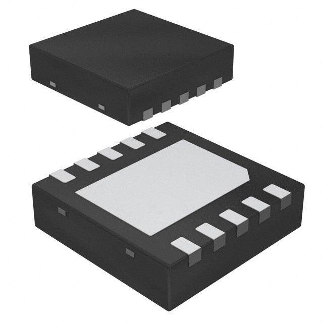
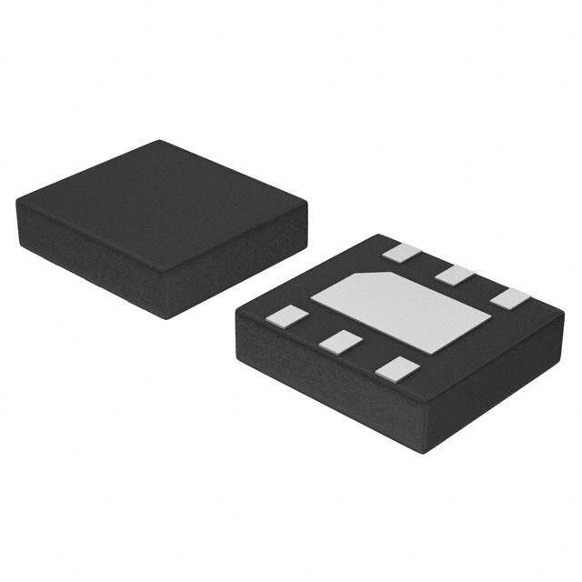
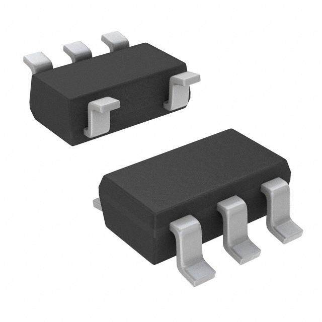
ICGOO电子元器件商城为您提供LP3982IMM-2.5/NOPB由Texas Instruments设计生产,在icgoo商城现货销售,并且可以通过原厂、代理商等渠道进行代购。 LP3982IMM-2.5/NOPB价格参考¥1.94-¥5.57。Texas InstrumentsLP3982IMM-2.5/NOPB封装/规格:PMIC - 稳压器 - 线性, Linear Voltage Regulator IC Positive Fixed 1 Output 2.5V 300mA 8-VSSOP。您可以下载LP3982IMM-2.5/NOPB参考资料、Datasheet数据手册功能说明书,资料中有LP3982IMM-2.5/NOPB 详细功能的应用电路图电压和使用方法及教程。
LP3982IMM-2.5/NOPB 是由德州仪器(Texas Instruments)生产的一款线性稳压器,属于 PMIC(电源管理集成电路)系列。其主要应用场景包括:

1. 便携式设备:LP3982IMM-2.5/NOPB 适用于电池供电的便携式设备,例如手机、平板电脑、便携式音频播放器等。它具有低功耗和小封装的特点,非常适合对空间和能效要求较高的应用。

2. 嵌入式系统:该稳压器可用于嵌入式系统中,为微控制器、传感器和其他低功耗组件提供稳定的电源电压。其 2.5V 的固定输出电压能够满足许多现代低功耗芯片的需求。

3. 消费电子:在消费电子产品中,如数码相机、电子书阅读器和可穿戴设备,LP3982IMM-2.5/NOPB 可以提供高效的电源管理解决方案,确保设备在低功耗模式下的稳定运行。

4. 通信设备:适用于需要低噪声电源的通信设备,例如无线模块、蓝牙设备和 Zigbee 模块。其良好的电源抑制比(PSRR)性能可以减少电源噪声对敏感电路的影响。

5. 工业应用:在工业自动化和控制系统中,LP3982IMM-2.5/NOPB 可以为数据采集模块、传感器接口和通信接口提供稳定的电源支持。

6. 医疗设备:对于一些便携式医疗设备,如脉搏血氧仪、血糖仪等,该稳压器可以提供可靠且低功耗的电源解决方案,确保设备长时间稳定工作。

总结来说,LP3982IMM-2.5/NOPB 的主要优势在于其低功耗、小尺寸和高稳定性,非常适合用于需要高效电源管理的各种低功耗应用场景。
| 参数 | 数值 |
| 产品目录 | 集成电路 (IC)半导体 |
| 描述 | IC REG LDO 2.5V 0.3A 8VSSOP低压差稳压器 Micropower, Ultra Low-Dropout, Low-Noise, 300mA CMOS Regulator 8-VSSOP -40 to 85 |
| 产品分类 | |
| 品牌 | Texas Instruments |
| 产品手册 | |
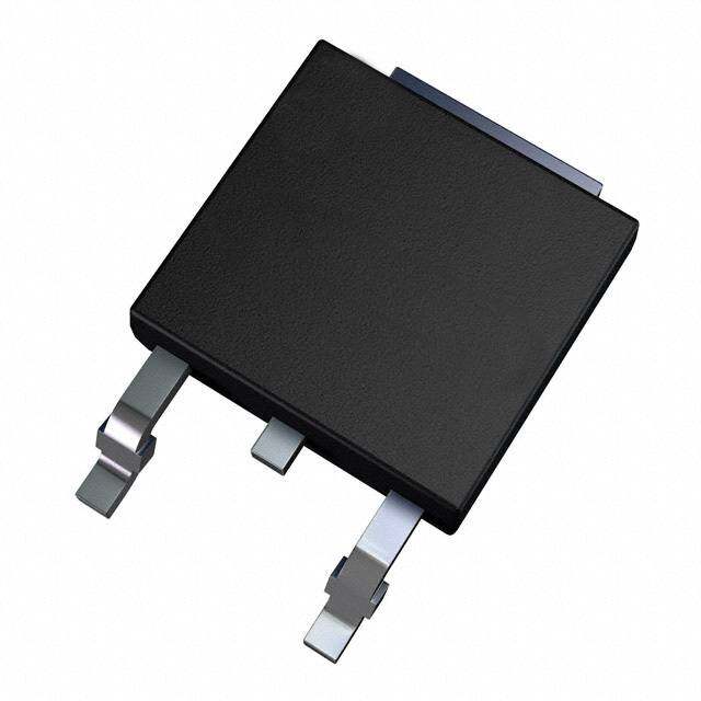
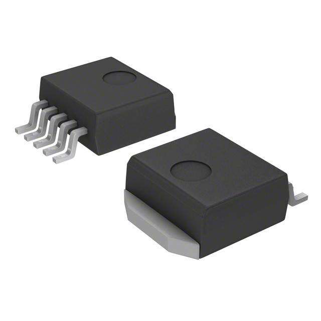
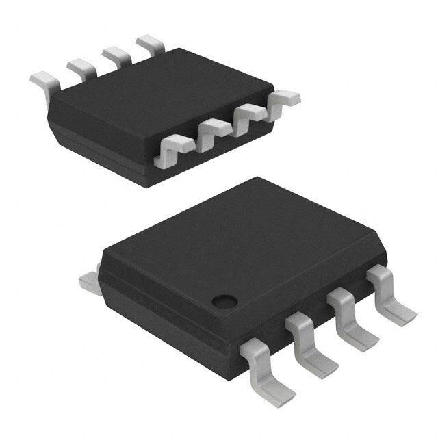
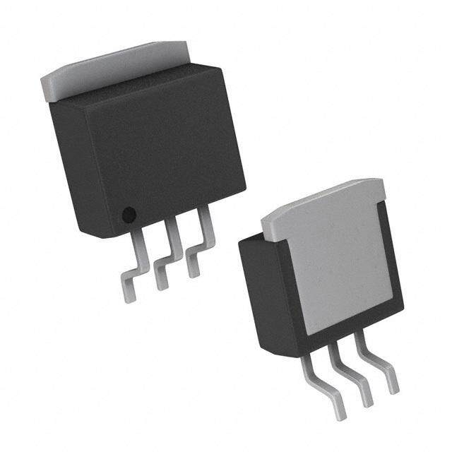
| 产品图片 |
|
| rohs | 符合RoHS无铅 / 符合限制有害物质指令(RoHS)规范要求 |
| 产品系列 | 电源管理 IC,低压差稳压器,Texas Instruments LP3982IMM-2.5/NOPB- |
| 数据手册 | |
| 产品型号 | LP3982IMM-2.5/NOPB |
| 产品 | Mircopower Ultra Low-Dropout Low-Noise CMOS Regulator |
| 产品目录页面 | |
| 产品种类 | 低压差稳压器 |
| 供应商器件封装 | 8-VSSOP |
| 其它名称 | LP3982IMM-2.5/NOPBDKR |
| 包装 | Digi-Reel® |
| 商标 | Texas Instruments |
| 回动电压—最大值 | 220 mV |
| 安装类型 | 表面贴装 |
| 安装风格 | SMD/SMT |
| 封装 | Reel |
| 封装/外壳 | 8-TSSOP,8-MSOP(0.118",3.00mm 宽) |
| 封装/箱体 | VSSOP-8 |
| 工作温度 | -40°C ~ 85°C |
| 工厂包装数量 | 1000 |
| 最大功率耗散 | 4.5 mW |
| 最大工作温度 | + 85 C |
| 最大输入电压 | 6 V |
| 最小工作温度 | - 40 C |
| 最小输入电压 | 2.5 V |
| 标准包装 | 1 |
| 电压-跌落(典型值) | 0.12V @ 300mA |
| 电压-输入 | 最高 6V |
| 电压-输出 | 2.5V |
| 电流-输出 | 300mA |
| 电流-限制(最小值) | 330mA |
| 稳压器拓扑 | 正,固定式 |
| 稳压器数 | 1 |
| 类型 | Low-dropout CMOS Linear Regulator |
| 系列 | LP3982 |
| 线路调整率 | 0.01 % |
| 设计资源 | http://www.digikey.com/product-highlights/cn/zh/texas-instruments-webench-design-center/3176 |
| 负载调节 | 0.002 % |
| 输出电压 | 2.5 V |
| 输出电压容差 | +/- 3 % |
| 输出电流 | 200 mA |
| 输出端数量 | 2 Output |
| 输出类型 | Fixed |





- 商务部:美国ITC正式对集成电路等产品启动337调查
- 曝三星4nm工艺存在良率问题 高通将骁龙8 Gen1或转产台积电
- 太阳诱电将投资9.5亿元在常州建新厂生产MLCC 预计2023年完工
- 英特尔发布欧洲新工厂建设计划 深化IDM 2.0 战略
- 台积电先进制程称霸业界 有大客户加持明年业绩稳了
- 达到5530亿美元!SIA预计今年全球半导体销售额将创下新高
- 英特尔拟将自动驾驶子公司Mobileye上市 估值或超500亿美元
- 三星加码芯片和SET,合并消费电子和移动部门,撤换高东真等 CEO
- 三星电子宣布重大人事变动 还合并消费电子和移动部门
- 海关总署:前11个月进口集成电路产品价值2.52万亿元 增长14.8%




PDF Datasheet 数据手册内容提取
Product Order Technical Tools & Support & Reference Folder Now Documents Software Community Design LP3982 SNVS185F–FEBRUARY2002–REVISEDAPRIL2017 LP3982 Micropower, Ultra-Low-Dropout, Low-Noise, 300-mA CMOS Regulator 1 Features 3 Description • 2.5-Vto6-VInputRange The LP3982 low-dropout (LDO) CMOS linear 1 regulatorisavailablein1.8-V,2.5-V,2.82-V,3-V, • MAX8860Pin,Package,andSpecification 3.3-V, and adjustable versions. They deliver 300 mA Compatible of output current. Packaged in an 8-pin VSSOP, the • 300-mAOutputCurrent LP3982 is pin- and package-compatible with Maxim's • 120-mVTypicalDropoutat300mA MAX8860. The LM3982 is also available in the small footprintWSONpackage. • 90-μATypicalQuiescentCurrent • 1-nATypicalShutdownMode The LP3982 suits battery-powered applications because of its shutdown mode (1 nA typical), low • 60-dBTypicalPSRR quiescent current (90 μA typical), and LDO voltage • 120-μsTypicalTurnonTime (120 mV typical). The low dropout voltage allows for • StableWithSmallCeramicOutputCapacitors more utilization of a battery’s available energy by operating closer to its end-of-life voltage. The LP3982 • 37-μV OutputVoltageNoise RMS device's PMOS output transistor consumes relatively (10Hzto100kHz) nodrivecurrentcomparedtoPNPLDOregulators. • Overtemperature/OvercurrentProtection This PMOS regulator is stable with small ceramic • ±2%OutputVoltageTolerance capacitiveloads(2.2μFtypical). • CreateaCustomDesignUsingtheLP3982With These devices also include regulation fault detection, theWEBENCH®PowerDesigner a bandgap voltage reference, constant current limiting,andthermal-overloadprotection. 2 Applications • WirelessHandsets DeviceInformation(1) • DSPCorePower PARTNUMBER PACKAGE BODYSIZE(NOM) • BatteryPoweredElectronics WSON(8) 2.50mm×3.00mm LP3982 • PortableInformationAppliances VSSOP(8) 3.00mm×3.00mm (1) For all available packages, see the orderable addendum at theendofthedatasheet. ApplicationCircuit(FixedV Version) OUT VIN VO IN OUT 2.2 PF 2.2 PF 100 CERAMIC k(cid:159) SHDN FAULT CC GND 33 nF 1 An IMPORTANT NOTICE at the end of this data sheet addresses availability, warranty, changes, use in safety-critical applications, intellectualpropertymattersandotherimportantdisclaimers.PRODUCTIONDATA.
LP3982 SNVS185F–FEBRUARY2002–REVISEDAPRIL2017 www.ti.com Table of Contents 1 Features.................................................................. 1 8 ApplicationandImplementation........................ 11 2 Applications........................................................... 1 8.1 ApplicationInformation............................................11 3 Description............................................................. 1 8.2 TypicalApplication .................................................11 4 RevisionHistory..................................................... 2 9 PowerSupplyRecommendations...................... 16 5 PinConfigurationandFunctions......................... 3 10 Layout................................................................... 17 6 Specifications......................................................... 4 10.1 LayoutGuidelines.................................................17 6.1 AbsoluteMaximumRatings......................................4 10.2 LayoutExample....................................................17 6.2 ESDRatings..............................................................4 10.3 WSONMounting...................................................17 6.3 RecommendedOperatingConditions.......................4 11 DeviceandDocumentationSupport................. 18 6.4 ThermalInformation..................................................4 11.1 DocumentationSupport .......................................18 6.5 ElectricalCharacteristics...........................................5 11.2 ReceivingNotificationofDocumentationUpdates18 6.6 TypicalCharacteristics..............................................7 11.3 CommunityResources..........................................18 7 DetailedDescription.............................................. 9 11.4 Trademarks...........................................................18 7.1 Overview...................................................................9 11.5 ElectrostaticDischargeCaution............................18 7.2 FunctionalBlockDiagram.........................................9 11.6 Glossary................................................................19 7.3 FeatureDescription...................................................9 12 Mechanical,Packaging,andOrderable Information........................................................... 19 7.4 DeviceFunctionalModes........................................10 4 Revision History NOTE:Pagenumbersforpreviousrevisionsmaydifferfrompagenumbersinthecurrentversion. ChangesfromRevisionE(October2015)toRevisionF Page • AddedlinksforWebenchandchangedtopnavigatoriconforTIDesigns ........................................................................... 1 ChangesfromRevisionD(April2013)toRevisionE Page • AddedDeviceInformationandPinConfigurationandFunctionssections,ESDRatingstable,FeatureDescription, DeviceFunctionalModes,ApplicationandImplementation,PowerSupplyRecommendations,Layout,Deviceand DocumentationSupport,andMechanical,Packaging,andOrderableInformationsections;updateThermalInformation...1 • DeletedleadtemperaturefromAbsMaxtable(inPOA);revisedwordingforfootnote4 ..................................................... 4 ChangesfromRevisionC(April2013)toRevisionD Page • ChangedlayoutofNationalDataSheettoTIformat............................................................................................................. 9 2 SubmitDocumentationFeedback Copyright©2002–2017,TexasInstrumentsIncorporated ProductFolderLinks:LP3982
LP3982 www.ti.com SNVS185F–FEBRUARY2002–REVISEDAPRIL2017 5 Pin Configuration and Functions DGKPackage 8-PinVSSOP TopView 1 8 OUT FAULT 2 7 IN SHDN 3 6 GND CC 4 5 OUT SET * TheSETpinisinternallydisconnectedforthefixedversions. NGMPackage 8-PinWSONWithThermalPad TopView OUT 1 8 FAULT IN 2 7 SHDN DAP GND 3 6 CC OUT 4 5 SET* TheSETpinisinternallydisconnectedforthefixedversions. PinFunctions PIN I/O DESCRIPTION NAME NO. ConnectacapacitorbetweenCCpinandgroundtoreducetheoutputnoise.Theoptimum CC 6 — valueforCCis33nF. FAULTpingoeslowduringoutofregulationconditionslikecurrentlimitandthermal FAULT 8 Output shutdown,orwhenitapproachesdropout.Requiresapullupresistorbecauseitisanactive- low,open-drainoutput. GND 3 Ground Ground IN 2 Input Thisistheinputsupplyvoltagetotheregulator. OUT 1,4 Output Regulatedoutputvoltage Intheadjustableversionaresistordividerconnectedtothispinsetstheoutputvoltage.The SET 5 Input SETpinisinternallydisconnectedforthefixedversions. TheSHDNpinallowstheparttobeturnedtoanONorOFFstatebypullingSHDNpinhigh SHDN 7 Input orlow. WSONOnly-TheDAP(DieAttachedPad)isanexposedpadthatdoesnothaveaninternal DAP √ — connection;itfunctionsasathermalreliefwhensolderedtoacopperplane.Itisrecommend thattheDAPbeconnectedtoGND.SeeWSONMountingsectionformoreinformation. Copyright©2002–2017,TexasInstrumentsIncorporated SubmitDocumentationFeedback 3 ProductFolderLinks:LP3982
LP3982 SNVS185F–FEBRUARY2002–REVISEDAPRIL2017 www.ti.com 6 Specifications 6.1 Absolute Maximum Ratings overoperatingfree-airtemperaturerange(unlessotherwisenoted)(1)(2)(3) MIN MAX UNIT V ,V ,V ,V ,V ,V −0.3 6.5 V IN OUT SHDN SET CC FAULT Faultsinkcurrent 20 mA Powerdissipation See(4) Junctiontemperature,T 150 °C J Storagetemperature,T –65 160 °C stg (1) StressesbeyondthoselistedunderAbsoluteMaximumRatingsmaycausepermanentdamagetothedevice.Thesearestressratings only,whichdonotimplyfunctionaloperationofthedeviceattheseoranyotherconditionsbeyondthoseindicatedunderRecommended OperatingConditions.Exposuretoabsolute-maximum-ratedconditionsforextendedperiodsmayaffectdevicereliability. (2) AllvoltagesarewithrespecttothepotentialattheGNDpin. (3) IfMilitary/Aerospace-specifieddevicesarerequired,contactTexasInstrumentsSalesOffice/Distributorsforavailabilityand specifications. (4) Inapplicationswherehighpowerdissipationand/orpoorthermalresistanceispresent,themaximumambienttemperaturemayhaveto bederated.Maximumambienttemperature(T )isdependantonthemaximumoperatingjunctiontemperature(T ),the A(MAX) J(MAX-OP) maximumpowerdissipation(P ),andthejunction-to-ambientthermalresistanceintheapplication(R ).Thisrelationshipisgiven D(MAX) θJA by:T =T −(P ×R ).ThevalueoftheR fortheWSONpackageisspecificallydependentonthePCBtrace A(MAX) J(MAX-OP) D(MAX) θJA θJA area,tracematerial,andthenumberoflayersandthermalvias.ForimprovedthermalresistanceandpowerdissipationfortheWSON package,refertoTIApplicationNoteAN-1187LeadlessLeadframePackage(LLP)(SNOA401). 6.2 ESD Ratings VALUE UNIT Human-bodymodel(HBM),perANSI/ESDA/JEDECJS-001(1) ±2000 V V Electrostaticdischarge (ESD) Machinemodel ±200 V (1) JEDECdocumentJEP155statesthat500-VHBMallowssafemanufacturingwithastandardESDcontrolprocess. 6.3 Recommended Operating Conditions(1)(2) MIN NOM MAX UNIT Operatingtemperature –40 85 °C Supplyvoltage 2.5 6 V (1) StressesbeyondthoselistedunderAbsoluteMaximumRatingsmaycausepermanentdamagetothedevice.Thesearestressratings only,whichdonotimplyfunctionaloperationofthedeviceattheseoranyotherconditionsbeyondthoseindicatedunderRecommended OperatingConditions.Exposuretoabsolute-maximum-ratedconditionsforextendedperiodsmayaffectdevicereliability. (2) AllvoltagesarewithrespecttothepotentialattheGNDpin. 6.4 Thermal Information LP3982 THERMALMETRIC(1) DGK(VSSOP) NGM(WSON)(2) UNIT 8PINS 8PINS R (3) Junction-to-ambientthermalresistance,High-K 175.2 52.6 °C/W θJA R Junction-to-case(top)thermalresistance 66.0 66.2 °C/W θJC(top) R Junction-to-boardthermalresistance 95.6 16.7 °C/W θJB ψ Junction-to-topcharacterizationparameter 9.7 1.9 °C/W JT ψ Junction-to-boardcharacterizationparameter 94.2 16.7 °C/W JB R Junction-to-case(bottom)thermalresistance n/a 11.1 °C/W θJC(bot) (1) Formoreinformationabouttraditionalandnewthermalmetrics,seetheSemiconductorandICPackageThermalMetricsapplication report. (2) ThePCBfortheWSON/NGNpackageR includesthermalviasundertheexposedthermalpadperEIA/JEDECJESD51-5. θJA (3) ThermalresistancevalueR isbasedontheEIA/JEDECHigh-Kprintedcircuitboarddefinedby:JESD51-7-HighEffectiveThermal θJA ConductivityTestBoardforLeadedSurfaceMountPackages. 4 SubmitDocumentationFeedback Copyright©2002–2017,TexasInstrumentsIncorporated ProductFolderLinks:LP3982
LP3982 www.ti.com SNVS185F–FEBRUARY2002–REVISEDAPRIL2017 6.5 Electrical Characteristics Unlessotherwisespecified,alllimitsarespecifiedforV =V +0.5V(1),V =V ,C =C =2.2μF,C =33nF,T IN OUT SHDN IN IN OUT CC J =25°C. PARAMETER TESTCONDITIONS MIN(2) TYP(3) MAX(2) UNIT V Inputvoltage Foroperatingtemperatureextremes: IN 2.5 6 V −40°Cto85°C 100μA≤I ≤300mA OUT V =V +0.5V(1) −2 2 IN OUT ΔV Outputvoltagetolerance SET=OUTfortheADJVersions %ofVOUT OUT (NOM) Foroperatingtemperatureextremes: −3 3 −40°Cto85°C Outputadjustrange ADJversiononly; V foroperatingtemperatureextremes: 1.25 6 V OUT −40°Cto85°C Maximumoutputcurrent AverageDCcurrentrating; I Foroperatingtemperatureextremes: 300 mA OUT −40°Cand85°C Outputcurrentlimit 770 ILIMIT Foroperatingtemperatureextremes: mA 330 −40°Cto85°C I =0mA 90 OUT I =0mA; OUT Supplycurrent foroperatingtemperatureextremes: 270 μA IQ −40°Cto85°C I =300mA 225 OUT Shutdownsupplycurrent V =0V,SHDN=GND 0.001 1 μA O I =1mA 0.4 OUT I =200mA 80 OUT VDO Dropoutvoltage(1)(4) IOUT=200mA; mV foroperatingtemperatureextremes: 220 −40°Cto85°C I =300mA 120 OUT I =1mA, (OVUT +0.5V)≤V ≤6V(1) 0.01 OUT I Lineregulation IOUT=1mA,(VOUT+0.5V)≤VI≤6 %/V ΔV V(1); OUT −0.1 0.1 foroperatingtemperatureextremes: −40°Cto85°C Loadregulation 100μA≤I ≤300mA 0.002 %/mA OUT Outputvoltagenoise I =10mA,10Hz≤f≤100kHz 37 μV OUT RMS e n Outputvoltagenoisedensity 10Hz≤f≤100kHz,C =10μF 190 nV/√Hz OUT V ,(V +0.5V)≤V ≤6V(1); IH OUT IN foroperatingtemperatureextremes: 2 −40°Cto85°C V SHDNinputthreshold V SHDN V ,(V +0.5V)≤V ≤6V(1); IL OUT IN foroperatingtemperature 0.4 extremes:−40°Cto85°C I SHDNinputbiascurrent SHDN=GNDorIN 0.1 100 nA SHDN I SETinputleakage SET=1.3V,ADJversiononly(5) 0.1 2.5 nA SET (1) Conditiondoesnotapplytoinputvoltagesbelow2.5Vbecausethisistheminimuminputoperatingvoltage. (2) Alllimitsareverifiedbytestingorstatisticalanalysis. (3) Typicalvaluesrepresentthemostlikelyparametricnorm. (4) DropoutvoltageismeasuredbyreducingV untilV drops100mVfromitsnominalvalueatV –V =0.5V.Dropoutvoltage IN OUT IN OUT doesnotapplytothe1.8-Vversion. (5) TheSETpinisnotexternallyconnectedforthefixedversions. Copyright©2002–2017,TexasInstrumentsIncorporated SubmitDocumentationFeedback 5 ProductFolderLinks:LP3982
LP3982 SNVS185F–FEBRUARY2002–REVISEDAPRIL2017 www.ti.com Electrical Characteristics (continued) Unlessotherwisespecified,alllimitsarespecifiedforV =V +0.5V(1),V =V ,C =C =2.2μF,C =33nF,T IN OUT SHDN IN IN OUT CC J =25°C. PARAMETER TESTCONDITIONS MIN(2) TYP(3) MAX(2) UNIT V ≥2.5V,I =200mA(6) 120 O OUT FAULTdetectionvoltage VOUT≥2.5V,IOUT=200mA(6); mV foroperatingtemperatureextremes: 280 −40°Cto85°C V FAULT I =2mA 0.115 SINK FAULToutputlowvoltage ISINK=2mA; V foroperatingtemperatureextremes: 0.25 −40°Cto85°C I FAULToff-leakagecurrent FAULT=3.6V,SHDN=0V 0.1 100 nA FAULT Thermalshutdowntemperature 160 T °C SD Thermalshutdownhysteresis 10 C =10μF,V at90%offinal T Start-uptime OUT OUT 120 μs ON value (6) TheFAULTdetectionvoltageisspecifiedfortheinput-to-outputvoltagedifferentialatwhichtheFAULTpingoesactivelow. 6 SubmitDocumentationFeedback Copyright©2002–2017,TexasInstrumentsIncorporated ProductFolderLinks:LP3982
LP3982 www.ti.com SNVS185F–FEBRUARY2002–REVISEDAPRIL2017 6.6 Typical Characteristics Unlessotherwisespecified,V =V +0.5V,C =C =2.2μF,C =33nF,T =25°C,V =V . IN O IN OUT CC J SHDN IN 140 160 VO = 2.77V 140 120 25(cid:176)C )Vm )Vm 120 ( EG 100 VO = 2.5V ( EG 100 85(cid:176)C AT 80 AT LO VO = 3.3V LO 80 V T 60 V T -40(cid:176)C U U 60 O O P 40 P O O 40 R R D D 20 20 0 0 0 50 100 150 200 250 300 0 50 100 150 200 250 300 LOAD CURRENT (mA) LOAD CURRENT (mA) Figure1.DropoutVoltagevsLoadCurrent Figure2.DropoutVoltagevsLoadCurrent (forDifferentOutputVoltages) (forDifferentOutputTemperatures) 180 240 )V 160 220 IL = 0mA m 200 ( DLOH 112400 FAULT = HIGH )A( TP 116800 TA = 85°C S N E E 140 TA = 25°C R 100 R HT RU 120 TC 80 FAULT = LOW C Y 100 E L T 60 P 80 E P D TLU 40 US 4600 TA = -40°C A 20 F 20 0 0 0 50 100 150 200 250 300 0 1 2 3 4 5 6 LOAD CURRENT (mA) INPUT VOLTAGE (V) Figure3.FAULTDetectThresholdvsLoadCurrent Figure4.SupplyCurrentvsInputVoltage 250 0 85(cid:176)C -10 )A 200 P 25(cid:176)C ( T -20 N ERRU 150 -40(cid:176)C )Bd( R -30 C R YL 100 SP -40 P P U -50 S 50 -60 0 -70 0 50 100 150 200 250 300 10 100 1k 10k 100k LOAD CURRENT (mA) FREQUENCY (Hz) Figure5.SupplyCurrentvsLoadCurrent Figure6.PowerSupplyRejectionRatiovsFrequency Copyright©2002–2017,TexasInstrumentsIncorporated SubmitDocumentationFeedback 7 ProductFolderLinks:LP3982
LP3982 SNVS185F–FEBRUARY2002–REVISEDAPRIL2017 www.ti.com Typical Characteristics (continued) Unlessotherwisespecified,V =V +0.5V,C =C =2.2μF,C =33nF,T =25°C,V =V . IN O IN OUT CC J SHDN IN 10 Hz) 1 V V/ COUT = 10PF ID E (P /VP OIS 00 N 0.1 1 COUT = 2.2PF 0.01 10 100 1k 100k k 1 ms/DIV FREQUENCY (Hz) Figure8.OutputNoise(10Hzto100kHz) Figure7.OutputNoiseSpectralDensity 2 1.8 V :)( E 11..46 ID/V 2 VSHDN C 0V NA 1.2 D E 1 P M I T 0.8 VOUT U P 0.6 T V UO 0.4 ID /V 0.2 1 0V 0 10 100 1k 10k 100k 500 Ps/DIV FREQUENCY (Hz) Figure10.ShutdownResponse Figure9.OutputImpedancevsFrequency V V FAULT DI ID 2 V/ FAULT VIN /V 2 VIN VIN VO V VO V ID/V VIN 1 V/DI VO 1 VO 5 mS/DIV 5 ms/DIV Figure11.Power-UpResponse Figure12.Power-DownResponse 8 SubmitDocumentationFeedback Copyright©2002–2017,TexasInstrumentsIncorporated ProductFolderLinks:LP3982
LP3982 www.ti.com SNVS185F–FEBRUARY2002–REVISEDAPRIL2017 7 Detailed Description 7.1 Overview The LP3982 is package, pin, and performance compatible with Maxim's MAX8860, excluding reverse battery protectionanddual-modefunction(fixedandadjustablecombined). A 1.25-V bandgap reference, an error amplifier, and a PMOS pass transistor perform voltage regulation while being supported by shutdown, fault, and the usual temperature and current protection circuitry (see Functional BlockDiagram). The regulator topology is the classic type with negative feedback from the output to one of the inputs of the error amplifier. Feedback resistors R1 and R2 are either internal or external to the device, depending on whether it is the fixed-voltage version or the adjustable version. The negative feedback and high open loop gain of the error amplifier cause the two inputs of the error amplifier to be virtually equal in voltage. If the output voltage changes due to load changes, the error amplifier provides the appropriate drive to the pass transistor to maintain the error amplifier'sinputsasvirtuallyequal.Inshort,theerroramplifierkeepstheoutputvoltageconstantinordertokeep itsinputsequal. 7.2 Functional Block Diagram IN OUT FAST START-UP CURRENT CIRCUIT LIMIT R1 + SET FAULT ERROR FAULT COMPARATORS AMP OFF - CC SHDN R2 1.25-V THERMAL BANDGAP PROTECTION GND 7.3 Feature Description 7.3.1 No-LoadStability The LP3982 remains stable during no-load conditions, a necessary feature for CMOS RAM keep-alive applications. 7.3.2 FastStart-Up The LP3982 provides fast start-up time for better system efficiency. The start-up speed is maintained when using the optional noise bypass capacitor. An internal 500-μA current source charges the capacitor until it reaches about90%ofitsfinalvalue. Copyright©2002–2017,TexasInstrumentsIncorporated SubmitDocumentationFeedback 9 ProductFolderLinks:LP3982
LP3982 SNVS185F–FEBRUARY2002–REVISEDAPRIL2017 www.ti.com 7.4 Device Functional Modes 7.4.1 Shutdown The LP3982 goes into sleep mode when the SHDN pin is in a logic low condition. During this condition, the pass transistor, error amplifier, and bandgap are turned off, reducing the supply current to 1 nA typical. The maximum voltage for a logic low at the SHDN pin is 0.4 V. A minimum voltage of 2 V at the SHDN pin turns the LP3982 back on. The SHDN pin may be directly tied to V to keep the part on. The SHDN pin may exceed V but not IN IN themaximumof6.5V. Figure 13 shows an application that uses the SHDN pin. It detects when the battery is too low and disconnects the load by turning off the regulator. A micropower comparator (LMC7215) and reference (LM385) are combined with resistors to set the minimum battery voltage. At the minimum battery voltage, the comparator output goes low and tuns off the LP3982 and corresponding load. Hysteresis is added to the minimum battery threshold to prevent the battery's recovery voltage from falsely indicating an above minimum condition. When the load is disconnected from the battery, it automatically increases in terminal voltage because of the reduced IR drop across its internal resistance. The minimum battery detector of Figure 13 has a low detection threshold (V ) of LT 3.6 V that corresponds to the minimum battery voltage. The upper threshold (V ) is set for 4.6 V to exceed the UT recoveryvoltageofthebattery. VB IN OUT R1 R4 R2 2.2PF 768k 180k 2.74M LP3982 100k C2.E2RPFAMIC + VB 4 Cells LMC7215 SHDN FAULT NiMH - GND R3 301k VREF LM385A-1.2V Figure13. MinimumBatteryDetectorthatDisconnectstheLoadViathe SHDNPinoftheLP3982 ResistorvalueforV andV aredeterminedasfollows: UT LT 1 1 1 GT = + + R1 R2 R3 VUT = R1 (VREF) GT VLT = R1 // R2 (VREF) GT (1) (TheapplicationofFigure13usedaG of5 μ mho.) T VUT1 R1 = VREF (GT) (2) 1 R2 = VREF (GT) 1 - VLT R1 (3) 1 R3 = 1 1 GT - R1 + R2 (4) The above procedure assumes a rail-to-rail output comparator. Essentially, R is in parallel with R prior to 2 1 reaching the lower threshold, then R becomes parallel with R for the upper threshold. Note that the application 2 3 requiresrail-to-railinputaswell. TheresistorvaluesshowninFigure13aretheclosestpracticaltocalculatedvalues. 10 SubmitDocumentationFeedback Copyright©2002–2017,TexasInstrumentsIncorporated ProductFolderLinks:LP3982
LP3982 www.ti.com SNVS185F–FEBRUARY2002–REVISEDAPRIL2017 8 Application and Implementation NOTE Information in the following applications sections is not part of the TI component specification, and TI does not warrant its accuracy or completeness. TI’s customers are responsible for determining suitability of components for their purposes. Customers should validateandtesttheirdesignimplementationtoconfirmsystemfunctionality. 8.1 Application Information The LP3982 can provide 300-mA output current with 2.5-V to 6-V input. It is stable with a 2.2-μF ceramic output capacitor. An optional external bypass capacitor reduces the output noise without slowing down the load transientresponse.Typicaloutputnoiseis37μV atfrequenciesfrom10Hzto100kHz.TypicalPSSRis RMS 60dBat1kHz. 8.2 Typical Application VIN VO IN OUT 2.2 PF 2.2 PF 100 CERAMIC k(cid:159) SHDN FAULT CC GND 33 nF Figure14. LP3982TypicalApplication(FixedV Version) OUT 8.2.1 DesignRequirements Fortypicalultralow-dropoutCMOS-regulatorapplications,usetheparameterslistedinTable1. Table1.DesignParameters DESIGNPARAMETER EXAMPLEVALUE Minimuminputvoltage V +0.5V OUT Nominaloutputvoltage 3.3V Maximumoutputcurrent 300mA RMSnoise,10Hzto100kHz 37µV RMS PSRRat1kHz 60dB 8.2.2 DetailedDesignProcedure 8.2.2.1 CustomDesignWithWEBENCH® Tools ClickheretocreateacustomdesignusingtheLP3982devicewiththeWEBENCH®PowerDesigner. 1. Startbyenteringtheinputvoltage(V ),outputvoltage(V ),andoutputcurrent(I )requirements. IN OUT OUT 2. Optimizethedesignforkeyparameterssuchasefficiency,footprint,andcostusingtheoptimizerdial. 3. ComparethegenerateddesignwithotherpossiblesolutionsfromTexasInstruments. The WEBENCH Power Designer provides a customized schematic along with a list of materials with real-time pricingandcomponentavailability. Copyright©2002–2017,TexasInstrumentsIncorporated SubmitDocumentationFeedback 11 ProductFolderLinks:LP3982
LP3982 SNVS185F–FEBRUARY2002–REVISEDAPRIL2017 www.ti.com Inmostcases,theseactionsareavailable: • Runelectricalsimulationstoseeimportantwaveformsandcircuitperformance • Runthermalsimulationstounderstandboardthermalperformance • ExportcustomizedschematicandlayoutintopopularCADformats • PrintPDFreportsforthedesign,andsharethedesignwithcolleagues GetmoreinformationaboutWEBENCHtoolsatwww.ti.com/WEBENCH. 8.2.2.2 OutputVoltageSetting(ADJVersionOnly) The output voltage is set according to the amount of negative feedback (the pass transistor inverts the feedback signal.) Figure 15 simplifies the topology of the LP3982. This type of regulator can be represented as an op amp configured as non-inverting amplifier and a fixed DC Voltage (V ) for its input signal. The special characteristic REF of this op amp is its extra-large output transistor that only sources current. In terms of its non-inverting configuration,theoutputvoltageequalsV timestheclosedloopgain: REF R1 VO = VREF R2 +1 (5) UseEquation6foradjustingtheoutputtoaparticularvoltage: é V ù R =R O -1 1 2 êë1.25V úû (6) ChooseR =100kΩtooptimizeaccuracy,powersupplyrejection,noise,andpowerconsumption. 2 VIN VREF + (cid:2) VOUT - R1 R2 Figure15. RegulatorTopologySimplified Similarity in the output capabilities exists between op amps and linear regulators. Just as rail-to-rail output op amps allow their output voltage to approach the supply voltage, low dropout regulators (LDOs) allow their output voltage to operate close to the input voltage. Both achieve this by the configuration of their output transistors. Standard operational amplifiers and regulator outputs are at the source (or emitter) of the output transistor. Rail- to-rail op amp and LDO regulator outputs are at the drain (or collector) of the output transistor. This replaces the threshold (or diode drop) limitations on the output with the less restrictive source-to-drain (or V ) limitations. SAT Thereisatrade-off;theoutputimpedancebecomesignificantlyhigher,thusprovidingacriticallylowerpolewhen combined with the capacitive load. That is why rail-to-rail operational amplifiers are usually poor at driving capacitive loads and a series output resistor recommended when doing so. LDOs require the same series resistance except that the internal resistance of the output capacitor will usually suffice. Refer to the Output Capacitancesectionformoreinformation. 8.2.2.3 OutputCapacitance The LP3982 is specifically designed to employ ceramic output capacitors as low as 2.2 μF. Ceramic capacitors below 10 μF offer significant cost and space savings, along with high frequency noise filtering. Higher values and othertypesandofcapacitormaybeused,buttheirequivalentseriesresistance(ESR)mustbemaintainedbelow 0.5 Ω. 12 SubmitDocumentationFeedback Copyright©2002–2017,TexasInstrumentsIncorporated ProductFolderLinks:LP3982
LP3982 www.ti.com SNVS185F–FEBRUARY2002–REVISEDAPRIL2017 Ceramic capacitor of the value required by the LP3982 are available in the following dielectric types: Z5U, Y5V, X5R, and X7R. The Z5U and Y5V types exhibit a 50% or more drop in capacitance value as their temperature increases from 25°C, an important consideration. The X5R generally maintain their capacitance value within ±20%.TheX7Rtypearedesirablefortheirtightertoleranceof10%overtemperature. Ceramic capacitors pose a challenge because of their relatively low ESR. Like most other LDOs, the LP3982 relies on a zero in the frequency response to compensate against excessive phase shift in the feedback loop of the regulator. If the phase shift reaches 360° (that is, becomes positive), the regulator oscillates. This compensation usually resides in the zero generated by the combination of the output capacitor with its ESR. The zero is intended to cancel the effects of the pole generated by the load capacitance (C ) combined with the L parallel combination of the load resistance (R ) and the output resistance (R ) of the regulator. The challenge L O posed by low ESR capacitors is that the zero it generates can be too high in frequency for the pole it is intended tocompensate.TheLP3982overcomesthischallengebyinternallygeneratingastrategicallyplacedzero. LOOP - GAIN RO VREF + R S E CL RL Figure16. SimplifiedModelofRegulatorLoopGainComponents Figure16showsabasicmodelforthelinearregulatorthathelpsdescribewhathappenstotheoutputsignalasit is processed through its feedback loop; that is, describe its loop gain (LG). The LG includes two main transfer functions: the error amplifier and the load. The error amplifier provides voltage gain and a dominant pole, while theloadprovidesazeroandapole.TheLGofthemodelinFigure16isdescribedbyEquation7: AO 1 + jω(ESR x CL) LG(jω)= * 1 +j ω 1 + jω((ESR + RO// RL) CL) ωPOLE (7) The first term of Equation 7 expresses the voltage gain (numerator) and a single pole role-off (denominator) of the error amplifier. The second term expresses the zero (numerator) and pole (denominator) of the load in combinationwiththeR oftheregulator. O Figure 17 shows a Bode plot that represents a case where the zero contributed by the load is too high to cancel the effect of the pole contributed by the load and R . The solid line represents the loop gain while the dashed O line represents the corresponding phase shift. Notice that the phase shift at unity gain is a total 360°, the criteria foroscillation. Copyright©2002–2017,TexasInstrumentsIncorporated SubmitDocumentationFeedback 13 ProductFolderLinks:LP3982
LP3982 SNVS185F–FEBRUARY2002–REVISEDAPRIL2017 www.ti.com ERROR AMP POLE: ZPOLE -180° LOOP GAIN 1/(2S (ESLRO A+D R POO //L REL)CL) SHIFTLOOP PHA S E 0 dB -360° LOAD ZERO 1/(2S (ESR x CL) Figure17. LoopGainBodePlotIllustratingInadequatelyHighZeroforStabilityCompensation The LP3982 generates an internal zero that makes up for the inadequately high zero of the low ESR ceramic output capacitor. This internally generated zero is strategically placed to provide positive phase shift near unity gain,thusprovidingastablephasemargin. 8.2.2.4 InputCapacitor The LP3982 requires a minimum input capacitance of about 1 μF. The value may be increased indefinitely. The type is not critical to stability. However, instability may occur with bench set-ups where long supply leads are used,particularlyatneardropoutandhighcurrentconditions.Thisisattributedtotheleadinductancecouplingto the output through the gate oxide of the pass transistor; thus, forming a pseudo LCR network within the loop gain. A 10-μF tantalum input capacitor remedies this non-situ condition; its larger ESR acts to dampen the pseudo-LCR network. This may only be necessary for some bench setups. A 1-μF ceramic input capacitor are fineformostend-useapplications. If a tantalum input capacitor is intended for the final application, it is important to consider their tendency to fail in shortcircuitmode,thuspotentiallydamagingthepart. 8.2.2.5 NoiseBypassCapacitor Thenoisebypasscapacitor(CC)significantlyreducesoutputnoiseoftheLP3982.Itconnectsbetweenpin6and ground.TheoptimumvalueforCCis33nF. Pin 6 directly connects to the high impedance output of the bandgap. The DC leakage of the CC capacitor must be considered; loading down the reference reduces the output voltage. NPO and COG ceramic capacitors typically offer very low leakage. Polypropylene and polycarbonate film carbonate capacitor offer even lower leakagecurrents. CC does not affect the transient response; however, it does affect turnon time. The smaller the CC value, the fastertheturnontime. 8.2.2.6 FaultDetection The LP3982 provides a FAULT pin that goes low during out of regulation conditions like current limit and thermal shutdown, or when it approaches dropout. The latter monitors the input-to-output voltage differential and compares it against a threshold that is slightly above the dropout voltage. This threshold also tracks the dropout voltageasitvarieswithloadcurrent.RefertoFigure3 intheTypicalCharacteristicssection. The FAULT pin requires a pullup resistor because it is an open-drain output. This resistor must be large in value toreduceenergydrain.A100-kΩ pullupresistorworkswellformostapplications. Figure 18 shows the LP3982 with delay added to the FAULT pin for the reset pin of a microprocessor. The outputofthecomparatorstayslowforapresetamountoftimeaftertheregulatorcomesoutofafaultcondition. 14 SubmitDocumentationFeedback Copyright©2002–2017,TexasInstrumentsIncorporated ProductFolderLinks:LP3982
LP3982 www.ti.com SNVS185F–FEBRUARY2002–REVISEDAPRIL2017 VIN VO = 3V IN OUT LP3982 RP 100k M SHDN ICR O FAULT + PR CDELAY OC GND CC LMC7225 RESET E S 0.1PF - SO R Figure18. Power-OnDelayedResetApplication ThedelaytimefortheapplicationofFigure18issetbyEquation8: -t CDELAY= VREF RPln 1- VO (8) The application is set for a reset delay time of 8.8 ms. The comparator must have high impedance inputs so as tonotloaddowntheV attheCCpinoftheLP3982. REF 8.2.2.7 PowerDissipation Knowing the device power dissipation and proper sizing of the thermal plane connected to the tab or pad is critical to ensuring reliable operation. Device power dissipation depends on input voltage, output voltage, and loadconditionsandcanbecalculatedwithEquation9: P =(V –V )×I (9) D(MAX) IN(MAX) OUT OUT(MAX) Power dissipation can be minimized, and greater efficiency can be achieved, by using the lowest available voltage drop option that would still be greater than the dropout voltage (V ). However, keep in mind that higher DO voltage drops result in better dynamic (that is, PSRR and transient) performance. On the WSON (NGM) package, the primary conduction path for heat is through the exposed power pad to the PCB. To ensure the device does not overheat, connect the exposed pad, through thermal vias, to an internal ground plane with an appropriate amount of copper PCB area. On the VSSOP (DGK) package, the primary conduction path for heat is through the pins to the PCB. The maximum allowable junction temperature (T ) determines maximum power J(MAX) dissipation allowed (P ) for the device package. Power dissipation and junction temperature are most often D(MAX) related by the junction-to-ambient thermal resistance (R ) of the combined PCB and device package and the θJA temperatureoftheambientair(T ),accordingtoEquation10orEquation11: A (T =T +(R ×P ) (10) J(MAX) A(MAX) θJA D(MAX) P =(T –T )/R (11) D(MAX) J(MAX) A(MAX) θJA R is highly dependent on the heat-spreading capability of the particular PCB design, and therefore varies θJA according to the total copper area, copper weight, and location of the planes. The R recorded in Thermal θJA Information is determined by the specific EIA/JEDEC JESD51-7 standard for PCB and copper-spreading area, and is to be used only as a relative measure of package thermal performance. For a well-designed thermal layout, R is the sum of the package junction-to-case (bottom) thermal resistance (R ) plus the thermal θJA θJCbot resistancecontributionbythePCBcopperareaactingasaheatsink. Improvements and absolute measurements of the R can be estimated by utilizing the thermal shutdown θJA circuitry that is internal to the device. The thermal shutdown turns off the pass transistor of the device when its junction temperature reaches 160°C (typical). The pass transistor does not turn on again until the junction temperaturedropsabout10°C(hysteresis). Using the thermal shutdown circuit to estimate, R can be as follows: with a low input-to-output voltage θJA differential, set the load current to 300 mA. Increase the input voltage until the thermal shutdown begins to cycle onandoff.ThenslowlydecreaseV (100-mVincrements)untilthedevicestayson.Recordtheresultingvoltage IN differential(V )anduseitinEquation12: D Copyright©2002–2017,TexasInstrumentsIncorporated SubmitDocumentationFeedback 15 ProductFolderLinks:LP3982
LP3982 SNVS185F–FEBRUARY2002–REVISEDAPRIL2017 www.ti.com (160 - T ) RTJA (0.300 x VAD) (12) 8.2.2.8 EstimatingJunctionTemperature The EIA/JEDEC standard recommends the use of psi (Ψ) thermal characteristics to estimate the junction temperatures of surface mount devices on a typical PCB board application. These characteristics are not true thermal resistance values, but rather package specific thermal characteristics that offer practical and relative means of estimating junction temperatures. These psi metrics are determined to be significantly independent of copper-spreading area. The key thermal characteristics (Ψ and Ψ ) are given in Thermal Information and are JT JB usedinaccordancewithEquation13orEquation14. T =T +(Ψ ×P ) J(MAX) TOP JT D(MAX) where • P isexplainedinEquation9. D(MAX) • T isthetemperaturemeasuredatthecenter-topofthedevicepackage. (13) TOP T =T +(Ψ ×P ) J(MAX) BOARD JB D(MAX) where • P isexplainedinEquation9. D(MAX) • T isthePCBsurfacetemperaturemeasured1-mmfromthedevicepackageandcenteredonthe BOARD packageedge. (14) Formoreinformationaboutthethermalcharacteristics Ψ and Ψ ,seetheTIApplicationReportSemiconductor JT JB andICPackageThermalMetrics(SPRA953),availablefordownloadatwww.ti.com. For more information about measuring T and T , see the TI Application Report Using New Thermal TOP BOARD Metrics(SBVA025),availablefordownloadatwww.ti.com. For more information about the EIA/JEDEC JESD51 PCB used for validating R , see the TI Application Report θJA Thermal Characteristics of Linear and Logic Packages Using JEDEC PCB Designs (SZZA017), available for downloadatwww.ti.com. 8.2.3 ApplicationCurves IL = IL = 300mA V 300mA 4.3V ID )V /V ( VNI m 02 VOUT 3.3V )V ID /V IOUT m V 0 ID 1 /A ( O m V 0 0 1 500 Ps/DIV 500(cid:3)Ps/DIV Figure19.LineTransientResponse Figure20.LoadTransient 9 Power Supply Recommendations TheLP3982isdesignedtooperatefromaninputvoltagesupplyrangebetween2.5Vand6V.Theinputvoltage range provides adequate headroom in order for the device to have a regulated output. This input supply must be well regulated. If the input supply is noisy, additional input capacitors with low ESR can help to improve the outputnoiseperformance. 16 SubmitDocumentationFeedback Copyright©2002–2017,TexasInstrumentsIncorporated ProductFolderLinks:LP3982
LP3982 www.ti.com SNVS185F–FEBRUARY2002–REVISEDAPRIL2017 10 Layout 10.1 Layout Guidelines BestperformanceisachievedbyplacingC ,C ,andC onthesamesideofthePCBastheLP3982device, IN OUT CC and as close as is practical to the package. The ground connections for C and C must be back to the IN OUT LP3982deviceGNDpinusingaswideandasshortofacoppertraceasispractical. Avoid connections using long trace lengths and narrow trace widths. These add parasitic inductances and resistancethatresultsininferiorperformanceespeciallyduringtransientconditions. 10.2 Layout Example VIA connect to ground layer VIA connect to V OUT C OUT R PULLUP OUT 1 8 FAULT IN 2 7 SHDN DAP C C CC IN (GND) GND 3 6 CC OUT 4 5 SET R1 R2 Figure21. WSONPackageAdjustableVersion(NottoScale) 10.3 WSON Mounting The WSON package requires specific mounting techniques which are detailed in TI Application Report Leadless Leadframe Package (LLP) (SNOA401). Referring to the section PCB Design Recommendations, the pad style which must be used with the WSON package is the NSMD (non-solder mask defined) type. Additionally, it is recommended the PCB terminal pads be 0.2 mm longer than the package pads to create a solder fillet to improve reliability and inspection. The thermal dissipation of the WSON package is directly related to the printed circuit board construction and the amount of additional copper area connected to the DAP. The DAP (exposed pad) on the bottom of the WSON package is connected to the die substrate with a conductive die attach adhesive. The DAP has no direct electrical (wire) connection to any of the pins. There is a parasitic PN junction between the die substrate and the device ground. As such, it is strongly recommend that the DAP be connected directly to the ground at device pin 3 (GND). Alternately, but not recommended, the DAP may be left floating (no electricalconnection).TheDAPmustnotbeconnectedtoanypotentialotherthanground. Copyright©2002–2017,TexasInstrumentsIncorporated SubmitDocumentationFeedback 17 ProductFolderLinks:LP3982
LP3982 SNVS185F–FEBRUARY2002–REVISEDAPRIL2017 www.ti.com 11 Device and Documentation Support 11.1 Documentation Support 11.1.1 RelatedDocumentation Foradditionalinformation,seethefollowing: • AN-1187LeadlessLeadframePackage(LLP) • SemiconductorandICPackageThermalMetrics • UsingNewThermalMetrics • ThermalCharacteristicsofLinearandLogicPackagesUsingJEDECPCBDesigns 11.1.2 DevelopmentSupport 11.1.2.1 CustomDesignWithWEBENCH® Tools ClickheretocreateacustomdesignusingtheLP3982devicewiththeWEBENCH®PowerDesigner. 1. Startbyenteringtheinputvoltage(V ),outputvoltage(V ),andoutputcurrent(I )requirements. IN OUT OUT 2. Optimizethedesignforkeyparameterssuchasefficiency,footprint,andcostusingtheoptimizerdial. 3. ComparethegenerateddesignwithotherpossiblesolutionsfromTexasInstruments. The WEBENCH Power Designer provides a customized schematic along with a list of materials with real-time pricingandcomponentavailability. Inmostcases,theseactionsareavailable: • Runelectricalsimulationstoseeimportantwaveformsandcircuitperformance • Runthermalsimulationstounderstandboardthermalperformance • ExportcustomizedschematicandlayoutintopopularCADformats • PrintPDFreportsforthedesign,andsharethedesignwithcolleagues GetmoreinformationaboutWEBENCHtoolsatwww.ti.com/WEBENCH. 11.2 Receiving Notification of Documentation Updates To receive notification of documentation updates, navigate to the device product folder on ti.com. In the upper right corner, click on Alert me to register and receive a weekly digest of any product information that has changed.Forchangedetails,reviewtherevisionhistoryincludedinanyreviseddocument. 11.3 Community Resources The following links connect to TI community resources. Linked contents are provided "AS IS" by the respective contributors. They do not constitute TI specifications and do not necessarily reflect TI's views; see TI's Terms of Use. TIE2E™OnlineCommunity TI'sEngineer-to-Engineer(E2E)Community.Createdtofostercollaboration amongengineers.Ate2e.ti.com,youcanaskquestions,shareknowledge,exploreideasandhelp solveproblemswithfellowengineers. DesignSupport TI'sDesignSupport QuicklyfindhelpfulE2Eforumsalongwithdesignsupporttoolsand contactinformationfortechnicalsupport. 11.4 Trademarks E2EisatrademarkofTexasInstruments. WEBENCHisaregisteredtrademarkofTexasInstruments. Allothertrademarksarethepropertyoftheirrespectiveowners. 11.5 Electrostatic Discharge Caution Thesedeviceshavelimitedbuilt-inESDprotection.Theleadsshouldbeshortedtogetherorthedeviceplacedinconductivefoam duringstorageorhandlingtopreventelectrostaticdamagetotheMOSgates. 18 SubmitDocumentationFeedback Copyright©2002–2017,TexasInstrumentsIncorporated ProductFolderLinks:LP3982
LP3982 www.ti.com SNVS185F–FEBRUARY2002–REVISEDAPRIL2017 11.6 Glossary SLYZ022—TIGlossary. Thisglossarylistsandexplainsterms,acronyms,anddefinitions. 12 Mechanical, Packaging, and Orderable Information The following pages include mechanical, packaging, and orderable information. This information is the most current data available for the designated devices. This data is subject to change without notice and revision of thisdocument.Forbrowser-basedversionsofthisdatasheet,refertotheleft-handnavigation. Copyright©2002–2017,TexasInstrumentsIncorporated SubmitDocumentationFeedback 19 ProductFolderLinks:LP3982
PACKAGE OPTION ADDENDUM www.ti.com 6-Feb-2020 PACKAGING INFORMATION Orderable Device Status Package Type Package Pins Package Eco Plan Lead/Ball Finish MSL Peak Temp Op Temp (°C) Device Marking Samples (1) Drawing Qty (2) (6) (3) (4/5) LP3982ILD-1.8/NOPB ACTIVE WSON NGM 8 1000 Green (RoHS SN Level-3-260C-168 HR -40 to 85 LNB & no Sb/Br) LP3982ILD-2.5/NOPB ACTIVE WSON NGM 8 1000 Green (RoHS SN Level-3-260C-168 HR -40 to 85 LPB & no Sb/Br) LP3982ILD-3.0/NOPB ACTIVE WSON NGM 8 1000 Green (RoHS NIPDAU | SN Level-3-260C-168 HR -40 to 85 LTB & no Sb/Br) LP3982ILD-3.3/NOPB ACTIVE WSON NGM 8 1000 Green (RoHS NIPDAU | SN Level-3-260C-168 HR -40 to 85 LUB & no Sb/Br) LP3982ILD-ADJ/NOPB ACTIVE WSON NGM 8 1000 Green (RoHS NIPDAU | SN Level-3-260C-168 HR -40 to 85 LVB & no Sb/Br) LP3982ILDX-1.8/NOPB ACTIVE WSON NGM 8 4500 Green (RoHS SN Level-3-260C-168 HR -40 to 85 LNB & no Sb/Br) LP3982ILDX-3.3/NOPB ACTIVE WSON NGM 8 4500 Green (RoHS NIPDAU | SN Level-3-260C-168 HR -40 to 85 LUB & no Sb/Br) LP3982ILDX-ADJ/NOPB ACTIVE WSON NGM 8 4500 Green (RoHS NIPDAU | SN Level-3-260C-168 HR -40 to 85 LVB & no Sb/Br) LP3982IMM-1.8/NOPB ACTIVE VSSOP DGK 8 1000 Green (RoHS SN Level-1-260C-UNLIM -40 to 85 LENB & no Sb/Br) LP3982IMM-2.5/NOPB ACTIVE VSSOP DGK 8 1000 Green (RoHS SN Level-1-260C-UNLIM -40 to 85 LEPB & no Sb/Br) LP3982IMM-3.0 NRND VSSOP DGK 8 1000 TBD Call TI Call TI -40 to 85 LETB LP3982IMM-3.0/NOPB ACTIVE VSSOP DGK 8 1000 Green (RoHS SN Level-1-260C-UNLIM -40 to 85 LETB & no Sb/Br) LP3982IMM-3.3 NRND VSSOP DGK 8 1000 TBD Call TI Call TI -40 to 85 LEUB LP3982IMM-3.3/NOPB ACTIVE VSSOP DGK 8 1000 Green (RoHS SN Level-1-260C-UNLIM -40 to 85 LEUB & no Sb/Br) LP3982IMM-ADJ ACTIVE VSSOP DGK 8 1000 TBD Call TI Call TI -40 to 85 LEVB LP3982IMM-ADJ/NOPB ACTIVE VSSOP DGK 8 1000 Green (RoHS SN Level-1-260C-UNLIM -40 to 85 LEVB & no Sb/Br) LP3982IMMX-1.8/NOPB ACTIVE VSSOP DGK 8 3500 Green (RoHS SN Level-1-260C-UNLIM -40 to 85 LENB & no Sb/Br) LP3982IMMX-2.5/NOPB ACTIVE VSSOP DGK 8 3500 Green (RoHS SN Level-1-260C-UNLIM -40 to 85 LEPB & no Sb/Br) Addendum-Page 1
PACKAGE OPTION ADDENDUM www.ti.com 6-Feb-2020 Orderable Device Status Package Type Package Pins Package Eco Plan Lead/Ball Finish MSL Peak Temp Op Temp (°C) Device Marking Samples (1) Drawing Qty (2) (6) (3) (4/5) LP3982IMMX-2.82/NOPB ACTIVE VSSOP DGK 8 3500 Green (RoHS SN Level-1-260C-UNLIM -40 to 85 LESB & no Sb/Br) LP3982IMMX-ADJ/NOPB ACTIVE VSSOP DGK 8 3500 Green (RoHS SN Level-1-260C-UNLIM -40 to 85 LEVB & no Sb/Br) (1) The marketing status values are defined as follows: ACTIVE: Product device recommended for new designs. LIFEBUY: TI has announced that the device will be discontinued, and a lifetime-buy period is in effect. NRND: Not recommended for new designs. Device is in production to support existing customers, but TI does not recommend using this part in a new design. PREVIEW: Device has been announced but is not in production. Samples may or may not be available. OBSOLETE: TI has discontinued the production of the device. (2) RoHS: TI defines "RoHS" to mean semiconductor products that are compliant with the current EU RoHS requirements for all 10 RoHS substances, including the requirement that RoHS substance do not exceed 0.1% by weight in homogeneous materials. Where designed to be soldered at high temperatures, "RoHS" products are suitable for use in specified lead-free processes. TI may reference these types of products as "Pb-Free". RoHS Exempt: TI defines "RoHS Exempt" to mean products that contain lead but are compliant with EU RoHS pursuant to a specific EU RoHS exemption. Green: TI defines "Green" to mean the content of Chlorine (Cl) and Bromine (Br) based flame retardants meet JS709B low halogen requirements of <=1000ppm threshold. Antimony trioxide based flame retardants must also meet the <=1000ppm threshold requirement. (3) MSL, Peak Temp. - The Moisture Sensitivity Level rating according to the JEDEC industry standard classifications, and peak solder temperature. (4) There may be additional marking, which relates to the logo, the lot trace code information, or the environmental category on the device. (5) Multiple Device Markings will be inside parentheses. Only one Device Marking contained in parentheses and separated by a "~" will appear on a device. If a line is indented then it is a continuation of the previous line and the two combined represent the entire Device Marking for that device. (6) Lead/Ball Finish - Orderable Devices may have multiple material finish options. Finish options are separated by a vertical ruled line. Lead/Ball Finish values may wrap to two lines if the finish value exceeds the maximum column width. Important Information and Disclaimer:The information provided on this page represents TI's knowledge and belief as of the date that it is provided. TI bases its knowledge and belief on information provided by third parties, and makes no representation or warranty as to the accuracy of such information. Efforts are underway to better integrate information from third parties. TI has taken and continues to take reasonable steps to provide representative and accurate information but may not have conducted destructive testing or chemical analysis on incoming materials and chemicals. TI and TI suppliers consider certain information to be proprietary, and thus CAS numbers and other limited information may not be available for release. In no event shall TI's liability arising out of such information exceed the total purchase price of the TI part(s) at issue in this document sold by TI to Customer on an annual basis. Addendum-Page 2
PACKAGE MATERIALS INFORMATION www.ti.com 4-Dec-2019 TAPE AND REEL INFORMATION *Alldimensionsarenominal Device Package Package Pins SPQ Reel Reel A0 B0 K0 P1 W Pin1 Type Drawing Diameter Width (mm) (mm) (mm) (mm) (mm) Quadrant (mm) W1(mm) LP3982ILD-1.8/NOPB WSON NGM 8 1000 178.0 12.4 3.3 2.8 1.0 8.0 12.0 Q1 LP3982ILD-2.5/NOPB WSON NGM 8 1000 178.0 12.4 3.3 2.8 1.0 8.0 12.0 Q1 LP3982ILD-3.0/NOPB WSON NGM 8 1000 180.0 12.4 3.3 2.8 1.0 8.0 12.0 Q1 LP3982ILD-3.3/NOPB WSON NGM 8 1000 180.0 12.4 3.3 2.8 1.0 8.0 12.0 Q1 LP3982ILD-ADJ/NOPB WSON NGM 8 1000 178.0 12.4 3.3 2.8 1.0 8.0 12.0 Q1 LP3982ILDX-1.8/NOPB WSON NGM 8 4500 330.0 12.4 3.3 2.8 1.0 8.0 12.0 Q1 LP3982ILDX-3.3/NOPB WSON NGM 8 4500 330.0 12.4 3.3 2.8 1.0 8.0 12.0 Q1 LP3982ILDX-ADJ/NOPB WSON NGM 8 4500 330.0 12.4 3.3 2.8 1.0 8.0 12.0 Q1 LP3982IMM-1.8/NOPB VSSOP DGK 8 1000 178.0 12.4 5.3 3.4 1.4 8.0 12.0 Q1 LP3982IMM-2.5/NOPB VSSOP DGK 8 1000 178.0 12.4 5.3 3.4 1.4 8.0 12.0 Q1 LP3982IMM-3.0 VSSOP DGK 8 1000 178.0 12.4 5.3 3.4 1.4 8.0 12.0 Q1 LP3982IMM-3.0/NOPB VSSOP DGK 8 1000 178.0 12.4 5.3 3.4 1.4 8.0 12.0 Q1 LP3982IMM-3.3 VSSOP DGK 8 1000 178.0 12.4 5.3 3.4 1.4 8.0 12.0 Q1 LP3982IMM-3.3/NOPB VSSOP DGK 8 1000 178.0 12.4 5.3 3.4 1.4 8.0 12.0 Q1 LP3982IMM-ADJ VSSOP DGK 8 1000 178.0 12.4 5.3 3.4 1.4 8.0 12.0 Q1 LP3982IMM-ADJ/NOPB VSSOP DGK 8 1000 178.0 12.4 5.3 3.4 1.4 8.0 12.0 Q1 LP3982IMMX-1.8/NOPB VSSOP DGK 8 3500 330.0 12.4 5.3 3.4 1.4 8.0 12.0 Q1 LP3982IMMX-2.5/NOPB VSSOP DGK 8 3500 330.0 12.4 5.3 3.4 1.4 8.0 12.0 Q1 PackMaterials-Page1
PACKAGE MATERIALS INFORMATION www.ti.com 4-Dec-2019 Device Package Package Pins SPQ Reel Reel A0 B0 K0 P1 W Pin1 Type Drawing Diameter Width (mm) (mm) (mm) (mm) (mm) Quadrant (mm) W1(mm) LP3982IMMX-2.82/NOPB VSSOP DGK 8 3500 330.0 12.4 5.3 3.4 1.4 8.0 12.0 Q1 LP3982IMMX-ADJ/NOPB VSSOP DGK 8 3500 330.0 12.4 5.3 3.4 1.4 8.0 12.0 Q1 *Alldimensionsarenominal Device PackageType PackageDrawing Pins SPQ Length(mm) Width(mm) Height(mm) LP3982ILD-1.8/NOPB WSON NGM 8 1000 210.0 185.0 35.0 LP3982ILD-2.5/NOPB WSON NGM 8 1000 210.0 185.0 35.0 LP3982ILD-3.0/NOPB WSON NGM 8 1000 195.0 200.0 45.0 LP3982ILD-3.3/NOPB WSON NGM 8 1000 195.0 200.0 45.0 LP3982ILD-ADJ/NOPB WSON NGM 8 1000 210.0 185.0 35.0 LP3982ILDX-1.8/NOPB WSON NGM 8 4500 367.0 367.0 35.0 LP3982ILDX-3.3/NOPB WSON NGM 8 4500 370.0 355.0 55.0 LP3982ILDX-ADJ/NOPB WSON NGM 8 4500 370.0 355.0 55.0 LP3982IMM-1.8/NOPB VSSOP DGK 8 1000 210.0 185.0 35.0 LP3982IMM-2.5/NOPB VSSOP DGK 8 1000 210.0 185.0 35.0 LP3982IMM-3.0 VSSOP DGK 8 1000 210.0 185.0 35.0 LP3982IMM-3.0/NOPB VSSOP DGK 8 1000 210.0 185.0 35.0 LP3982IMM-3.3 VSSOP DGK 8 1000 210.0 185.0 35.0 LP3982IMM-3.3/NOPB VSSOP DGK 8 1000 210.0 185.0 35.0 LP3982IMM-ADJ VSSOP DGK 8 1000 210.0 185.0 35.0 PackMaterials-Page2
PACKAGE MATERIALS INFORMATION www.ti.com 4-Dec-2019 Device PackageType PackageDrawing Pins SPQ Length(mm) Width(mm) Height(mm) LP3982IMM-ADJ/NOPB VSSOP DGK 8 1000 210.0 185.0 35.0 LP3982IMMX-1.8/NOPB VSSOP DGK 8 3500 367.0 367.0 35.0 LP3982IMMX-2.5/NOPB VSSOP DGK 8 3500 367.0 367.0 35.0 LP3982IMMX-2.82/NOPB VSSOP DGK 8 3500 367.0 367.0 35.0 LP3982IMMX-ADJ/NOPB VSSOP DGK 8 3500 367.0 367.0 35.0 PackMaterials-Page3
None
None
MECHANICAL DATA NGM0008C LDA08C (Rev B) www.ti.com
IMPORTANTNOTICEANDDISCLAIMER TI PROVIDES TECHNICAL AND RELIABILITY DATA (INCLUDING DATASHEETS), DESIGN RESOURCES (INCLUDING REFERENCE DESIGNS), APPLICATION OR OTHER DESIGN ADVICE, WEB TOOLS, SAFETY INFORMATION, AND OTHER RESOURCES “AS IS” AND WITH ALL FAULTS, AND DISCLAIMS ALL WARRANTIES, EXPRESS AND IMPLIED, INCLUDING WITHOUT LIMITATION ANY IMPLIED WARRANTIES OF MERCHANTABILITY, FITNESS FOR A PARTICULAR PURPOSE OR NON-INFRINGEMENT OF THIRD PARTY INTELLECTUAL PROPERTY RIGHTS. These resources are intended for skilled developers designing with TI products. You are solely responsible for (1) selecting the appropriate TI products for your application, (2) designing, validating and testing your application, and (3) ensuring your application meets applicable standards, and any other safety, security, or other requirements. These resources are subject to change without notice. TI grants you permission to use these resources only for development of an application that uses the TI products described in the resource. Other reproduction and display of these resources is prohibited. No license is granted to any other TI intellectual property right or to any third party intellectual property right. TI disclaims responsibility for, and you will fully indemnify TI and its representatives against, any claims, damages, costs, losses, and liabilities arising out of your use of these resources. TI’s products are provided subject to TI’s Terms of Sale (www.ti.com/legal/termsofsale.html) or other applicable terms available either on ti.com or provided in conjunction with such TI products. TI’s provision of these resources does not expand or otherwise alter TI’s applicable warranties or warranty disclaimers for TI products. Mailing Address: Texas Instruments, Post Office Box 655303, Dallas, Texas 75265 Copyright © 2020, Texas Instruments Incorporated

 Datasheet下载
