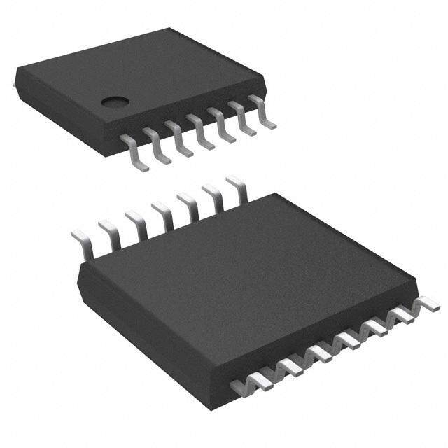
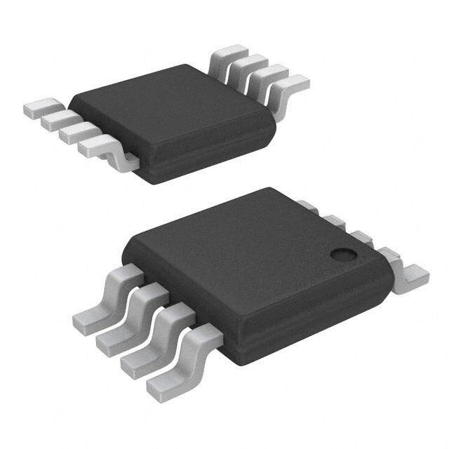
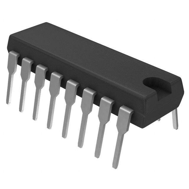
- 型号: LP339M/NOPB
- 制造商: Texas Instruments
- 库位|库存: xxxx|xxxx
- 要求:
| 数量阶梯 | 香港交货 | 国内含税 |
| +xxxx | $xxxx | ¥xxxx |
查看当月历史价格
查看今年历史价格
LP339M/NOPB产品简介:
ICGOO电子元器件商城为您提供LP339M/NOPB由Texas Instruments设计生产,在icgoo商城现货销售,并且可以通过原厂、代理商等渠道进行代购。 LP339M/NOPB价格参考¥3.13-¥7.74。Texas InstrumentsLP339M/NOPB封装/规格:线性 - 比较器, 通用 比较器 CMOS,MOS,开路集电极 14-SOIC。您可以下载LP339M/NOPB参考资料、Datasheet数据手册功能说明书,资料中有LP339M/NOPB 详细功能的应用电路图电压和使用方法及教程。
| 参数 | 数值 |
| 产品目录 | 集成电路 (IC)半导体 |
| CMRR,PSRR(典型值) | - |
| 描述 | IC COMPARATOR QUAD LO PWR 14SOIC模拟比较器 LOW PWR QUAD COMP |
| 产品分类 | |
| 品牌 | Texas Instruments |
| 产品手册 | |
| 产品图片 |
|
| rohs | 符合RoHS无铅 / 符合限制有害物质指令(RoHS)规范要求 |
| 产品系列 | 校验器 IC,Texas Instruments LP339M/NOPB- |
| 数据手册 | |
| 产品型号 | LP339M/NOPB |
| 产品 | Analog Comparators |
| 产品目录页面 | |
| 产品种类 | 模拟比较器 |
| 传播延迟(最大值) | - |
| 供应商器件封装 | 14-SOICN |
| 偏转电压—最大值 | 5 mV |
| 元件数 | 4 |
| 其它名称 | *LP339M/NOPB |
| 包装 | 管件 |
| 响应时间 | 8 us |
| 商标 | Texas Instruments |
| 安装类型 | 表面贴装 |
| 安装风格 | SMD/SMT |
| 封装 | Tube |
| 封装/外壳 | 14-SOIC(0.154",3.90mm 宽) |
| 封装/箱体 | SOIC-14 |
| 工作温度 | 0°C ~ 70°C |
| 工厂包装数量 | 55 |
| 标准包装 | 55 |
| 比较器类型 | General Purpose |
| 滞后 | - |
| 电压-电源,单/双 (±) | 2 V ~ 36 V, ±1 V ~ 18 V |
| 电压-输入失调(最大值) | 5mV @ 5V |
| 电流-输入偏置(最大值) | 0.025µA @ 5V |
| 电流-输出(典型值) | 10mA @ 5V |
| 电流-静态(最大值) | 100µA |
| 电源电压-最大 | 36 V |
| 电源电压-最小 | 2 V |
| 电源电流 | 21.25 uA |
| 电源电流—最大值 | 21.25 uA |
| 类型 | 通用 |
| 系列 | LP339-N |
| 输出类型 | Open Collector, Open Drain |
| 通道数量 | 4 Channel |


- 商务部:美国ITC正式对集成电路等产品启动337调查
- 曝三星4nm工艺存在良率问题 高通将骁龙8 Gen1或转产台积电
- 太阳诱电将投资9.5亿元在常州建新厂生产MLCC 预计2023年完工
- 英特尔发布欧洲新工厂建设计划 深化IDM 2.0 战略
- 台积电先进制程称霸业界 有大客户加持明年业绩稳了
- 达到5530亿美元!SIA预计今年全球半导体销售额将创下新高
- 英特尔拟将自动驾驶子公司Mobileye上市 估值或超500亿美元
- 三星加码芯片和SET,合并消费电子和移动部门,撤换高东真等 CEO
- 三星电子宣布重大人事变动 还合并消费电子和移动部门
- 海关总署:前11个月进口集成电路产品价值2.52万亿元 增长14.8%


PDF Datasheet 数据手册内容提取
LP339 LP339 Ultra-Low Power Quad Comparator Literature Number: SNOSBE0A
L August2000 P 3 3 9 U LP339 lt r a Ultra-Low Power Quad Comparator - L o General Description n Singlesupplyoperation w n Sensingatground P The LP339 consists of four independent voltage compara- n CompatiblewithCMOSlogicfamily o tors designed specifically to operate from a single power n Pin-outidenticaltoLM339 w supply and draw typically 60 µAof power supply drain cur- e rentoverawiderangeofpowersupplyvoltages.Operation Features r from split supplies is also possible and the ultra-low power Q supplydraincurrentisindependentofthepowersupplyvolt- n Ultra-lowpowersupplycurrentdrain age. These comparators also feature a common-mode (60µA)—independentofthesupplyvoltage u a range which includes ground, even when operated from a (75µW/comparatorat+5VDC) d singlesupply. n Lowinputbiasingcurrent: 3nA C Applications include limit comparators, simple n Lowinputoffsetcurrent: ±0.5nA o analog-to-digital converters, pulse, square and time delay n Lowinputoffsetvoltage: ±2mV m generators; VCO’s; multivibrators; high voltage logic gates. n Inputcommon-modevoltageincludesground The LP339 was specifically designed to interface with the p CMOS logic family.The ultra-low supply current makes the n OutputvoltagecompatiblewithMOSandCMOSlogic a n Highoutputsinkcurrentcapability(30mAatV =2V ) r LP339valuableinbatterypoweredapplications. O DC a n SupplyInputprotectedagainstreversevoltages t o Advantages r n Ultra-lowpowersupplydrainsuitableforbattery applications Schematic and Connection Diagrams DS005226-2 OrderNumberLP339MforS.O.Package DS005226-1 SeeNSPackageNumberM14A OrderNumberLP339NforDual-In-LinePackage SeeNSPackageNumberN14A Typical Applications (V+= 5.0 V ) DC BasicComparator DrivingCMOS DS005226-3 DS005226-4 ©2000NationalSemiconductorCorporation DS005226 www.national.com
9 3 3 Absolute Maximum Ratings (Note 1) OperatingTemperatureRange 0˚Cto+70˚C P L If Military/Aerospace specified devices are required, StorageTemperatureRange −65˚to+150˚C pleasecontacttheNationalSemiconductorSalesOffice/ SolderingInformation: Distributorsforavailabilityandspecifications. Dual-In-LinePackage(10sec.) +260˚C SupplyVoltage 36V or ±18V S.O.Package: DC DC DifferentialInputVoltage ±36V VaporPhase(60sec.) +215˚C DC InputVoltage −0.3V to36V Infrared(15sec.) +220˚C DC DC PowerDissipation(Note2) SeeAN-450“SurfaceMountingMethodsandTheirEffecton Product Reliability” for other methods of soldering surface MoldedDIP 570mW mountdevices. OutputShortCircuittoGND(Note3) Continuous InputCurrentV <−0.3V (Note4) 50mA IN DC Electrical Characteristics (V+=5V )(Note5) DC Parameter Conditions Min Typ Max Units InputOffsetVoltage T =25˚C(Note10) ±2 ±5 mV A DC InputBiasCurrent I (+)orI (−)withthe 2.5 25 nA IN IN DC OutputintheLinearRange,T =25˚C(Note6) A InputOffsetCurrent I (+)−I (−),T =25˚C ±0.5 ±5 nA IN IN A DC InputCommon T =25˚C(Note7) 0 V+−1.5 V A DC ModeVoltageRange SupplyCurrent R =InfiniteonallComparators,T =25˚C 60 100 µA L A DC VoltageGain V = 1V to11V , 500 V/mV O DC DC R =15kW ,V+=15V ,T =25˚C L DC A LargeSignal V =TTLLogicSwing,V =1.4V , 1.3 µSec IN REF DC ResponseTime V =5V ,R =5.1kW ,T =25˚C RL DC L A ResponseTime V =5V ,R =5.1kW ,T =25˚C(Note8) 8 µSec RL DC L A OutputSinkCurrent V (−)=1V ,V (+)=0,V =2V , 15 30 mA IN DC IN O DC DC T =25˚C(Note12) A V =0.4V 0.20 0.70 mA O DC DC OutputLeakageCurrent V (+)=1V ,V (−)=0,V =5V ,T =25˚C 0.1 nA IN DC IN O DC A DC InputOffsetVoltage (Note10) ±9 mV DC InputOffsetCurrent I (+)−I (−) ±1 ±15 nA IN IN DC InputBiasCurrent I (+)orI (−)withOutputinLinearRange 4 40 nA IN IN DC InputCommon SingleSupply 0 V+−2.0 V DC ModeVoltageRange OutputSinkCurrent V (−)=1V ,V (+)=0,V =2V 10 mA IN DC IN O DC DC OutputLeakageCurrent V (+)=1V ,V (−)=0,V =30V 1.0 µA IN DC IN O DC DC DifferentialInputVoltage AllV ‡ 0V (orV−onsplitsupplies)(Note9) 36 V IN’s DC DC Note1: AbsoluteMaximumRatingsindicatelimitsbeyondwhichdamagetothedevicemayoccur.OperatingRatingsindicateconditionsforwhichthedeviceisfunc- tional,butdonotguaranteespecificperformancelimits. Note2: Forelevatedtemperatureoperation,Tjmaxis125˚CfortheLP339.q ja(junctiontoambient)is175˚C/WfortheLP339Nand120˚C/WfortheLP339Mwhen eitherdeviceissolderedinaprintedcircuitboardinastillairenvironment.Thelowbiasdissipationandthe“ON-OFF”characteristicoftheoutputskeepsthechip dissipationverysmall(PD£ 100mW),providedtheoutputtransistorsareallowedtosaturate. Note3: ShortcircuitsfromtheoutputtoV+cancauseexcessiveheatingandeventualdestruction.Themaximumoutputcurrentisapproximately50mA. Note4: Thisinputcurrentwillonlyexistwhenthevoltageatanyoftheinputleadsisdrivennegative.Itisduetothecollector-basejunctionoftheinputPNPtran- sistorsbecomingforwardbiasedandtherebyactingasinputclampdiodes.Inadditiontothisdiodeaction,thereisalsolateralNPNparasitictransistoractiononthe ICchip.ThistransistoractioncancausetheoutputvoltageofthecomparatorstogototheV+voltagelevel(ortogroundforalargeinputoverdrive)forthetimedu- rationthataninputisdrivennegative.Thisisnotdestructiveandnormaloutputstateswillre-establishwhentheinputvoltage,whichisnegative,againreturnstoa valuegreaterthan−0.3VDC(TA=25˚C). Note5: ThesespecificationsapplyforV+=5VDCand0˚C£ TA£ 70˚C,unlessotherwisestated.Thetemperatureextremesareguaranteedbutnot100%production tested.TheseparametersarenotusedtocalculateoutgoingAQL. Note6: ThedirectionoftheinputcurrentisoutoftheICduetothePNPinputstage.Thiscurrentisessentiallyconstant,independentofthestateoftheoutput,so noloadingchangeexistsonthereferenceortheinputlinesaslongasthecommon-moderangeisnotexceeded. Note7: Theinputcommon-modevoltageoreitherinputvoltageshouldnotbeallowedtogonegativebymorethan0.3V.Theupperendofthecommon-modevolt- agerangeisV+−1.5V(TA=25˚C),buteitherorbothinputscangoto30VDCwithoutdamage. Note8: Theresponsetimespecifiedisfora100mVinputstepwith5mVoverdrive.Forlargeroverdrivesignals1.3µscanbeobtained.SeeTypicalPerformance Characteristicssection. www.national.com 2
L Electrical Characteristics P (Continued) 3 3 9 Note9: Positiveexcursionsofinputvoltagemayexceedthepowersupplylevel.Aslongastheothervoltageremainswithinthecommon-moderange,thecompara- torwillprovideaproperoutputstate.Thelowinputvoltagestatemustnotbelessthan−0.3VDC(or0.3VDCbelowthemagnitudeofthenegativepowersupply,if used)atTA=25˚C. Note10: Atoutputswitchpoint,VO=1.4V,RS=0W withV+from5VDC;andoverthefullinputcommon-moderange(0VDCtoV+−1.5VDC). Note11: ForinputsignalsthatexceedV+,onlytheoverdrivencomparatorisaffected.Witha5Vsupply,VINshouldbelimitedto25Vmaximum,andalimitingresistor shouldbeusedonallinputsthatmightexceedthepositivesupply. Note12: Theoutputsinkcurrentisafunctionoftheoutputvoltage.TheLP339hasabi-modaloutputsectionwhichallowsittosinklargecurrentsviaaDarlington connectionatoutputvoltagesgreaterthanapproximately1.5VDCandsinklowercurrentsbelowthispoint.(Seetypicalcharacteristicssectionandapplicationssec- tion). Typical Performance Characteristics SupplyCurrent InputCurrent OutputSinkCurrent DS005226-35 DS005226-36 DS005226-37 OutputSinkCurrent ResponseTimesfor ResponseTimesfor VariousInput VariousInput Overdrives — Overdrives — NegativeTransition PositiveTransition DS005226-38 DS005226-39 DS005226-40 3 www.national.com
9 3 3 Application Hints Notice that the output section is configured in a Darlington P connection(ignoringQ3).Therefore,iftheoutputvoltageis L All pins of any unused comparators should be tied to the held high enough (V ‡ 1 V ), Q1 is not saturated and the O DC negativesupply. output current is limited only by the product of the betas of The bias network of the LP339 establishes a drain current Q1,Q2andI1(andthe60W R ofQ2).TheLP339isthus SAT whichisindependentofthemagnitudeofthepowersupply capable of driving LED’s, relays, etc. in this mode while voltageovertherangeoffrom2V to30V . maintaining an ultra-low power supply current of typically DC DC It is usually unnecessary to use a bypass capacitor across 60µA. thepowersupplyline. IftransistorQ3wereomitted,andtheoutputvoltageallowed ThedifferentialinputvoltagemaybelargerthanV+without to drop below about 0.8 VDC, transistor Q1 would saturate damagingthedevice.Protectionshouldbeprovidedtopre- andtheoutputcurrentwoulddroptozero.Thecircuitwould, venttheinputvoltagesfromgoingnegativemorethan−0.3 therefore, be unable to “pull” low current loads down to V (at25˚C).Aninputclampdiodecanbeusedasshown ground (or the negative supply, if used).Transistor Q3 has DC intheapplicationsection. been included to bypass transistor Q1 under these condi- tionsandapplythecurrentI1directlytothebaseofQ2.The The output section of the LP339 has two distinct modes of outputsinkcurrentisnowapproximatelyI1timesthebetaof operation-aDarlingtonmodeandagroundedemittermode. Q2(700µAatV =0.4V ).TheoutputoftheLP339exhib- ThisuniquedrivecircuitpermitstheLP339tosink30mAat O DC its a bi-modal characteristic with a smooth transition be- V =2 V (Darlington mode) and 700 µA at V =0.4 V O DC O DC tween modes. (See Output Sink Current graphs in Typical (groundedemittermode).Figure1isasimplifiedschematic PerformanceCharacteristicssection.) diagramoftheLP339outputsection. Itisalsoimportanttonotethatinbothcasestheoutputisan uncommitted collector. Therefore, many collectors can be tiedtogethertoprovideanoutputOR’ingfunction.Anoutput pull-up resistor can be connected to any available power supply voltage within the permitted power supply voltage range and there is no restriction on this voltage due to the magnitudeofthevoltagewhichisappliedtotheV+terminal oftheLP339package. DS005226-11 FIGURE1. www.national.com 4
L P Typical Applications (V+=15 V ) 3 DC 3 9 One-ShotMultivibrator DS005226-13 Time-DelayGenerator DS005226-15 5 www.national.com
9 3 3 Typical Applications (V+=15 V ) (Continued) P DC L ORingtheOutputs DS005226-16 SquarewaveOscillator DS005226-17 www.national.com 6
L Typical Applications (V+=15 V ) (Continued) P3 DC 3 9 ThreeLevelAudioPeakIndicator DS005226-19 LEDDriver DS005226-22 PulseGenerator DS005226-18 7 www.national.com
9 3 3 Typical Applications (V+=15 V ) (Continued) P DC L Bi-StableMultivibrator DS005226-21 RelayDriver DS005226-23 BuzzerDriver ComparatorWith60mASinkCapability DS005226-24 DS005226-25 www.national.com 8
L Typical Applications (V+=15 V ) (Continued) P3 DC 3 9 Non-InvertingComparatorwithHysteresis InvertingComparatorwithHysteresis DS005226-26 DS005226-27 ComparingInputVoltages BasicComparator OutputStrobing ofOppositePolarity DS005226-29 DS005226-30 DS005226-28 TransducerAmplifier ZeroCrossingDetector(SinglePowerSupply) DS005226-32 DS005226-31 9 www.national.com
9 3 3 Typical Applications (V+=15 V ) (Continued) P DC L Split-SupplyApplications ComparatorWithaNegativeReference ZeroCrossingDetector DS005226-34 DS005226-33 www.national.com 10
L P Physical Dimensions inches (millimeters) unless otherwise noted 3 3 9 S.O.Package(M) OrderNumberLP339MorLP339MX NSPackageM14A MoldedDual-In-LinePackage(N) OrderNumberLP339N NSPackageNumberN14A 11 www.national.com
r o Notes t a r a p m o C d a u Q r e w o P w o L - a r t l U 9 3 3 P L LIFESUPPORTPOLICY NATIONAL’S PRODUCTS ARE NOT AUTHORIZED FOR USE AS CRITICAL COMPONENTS IN LIFE SUPPORT DEVICES OR SYSTEMS WITHOUT THE EXPRESS WRITTEN APPROVAL OF THE PRESIDENT AND GENERAL COUNSELOFNATIONALSEMICONDUCTORCORPORATION.Asusedherein: 1. Life support devices or systems are devices or 2. A critical component is any component of a life systems which, (a) are intended for surgical implant support device or system whose failure to perform into the body, or (b) support or sustain life, and can be reasonably expected to cause the failure of whose failure to perform when properly used in the life support device or system, or to affect its accordance with instructions for use provided in the safetyoreffectiveness. labeling, can be reasonably expected to result in a significantinjurytotheuser. NationalSemiconductor NationalSemiconductor NationalSemiconductor NationalSemiconductor Corporation Europe AsiaPacificCustomer JapanLtd. Americas Fax: +49(0)180-5308586 ResponseGroup Tel: 81-3-5639-7560 Tel:1-800-272-9959 Email: europe.support@nsc.com Tel:65-2544466 Fax:81-3-5639-7507 Fax:1-800-737-7018 Deutsch Tel: +49(0)6995086208 Fax:65-2504466 Email:support@nsc.com English Tel: +44(0)8702402171 Email:ap.support@nsc.com www.national.com FrançaisTel: +33(0)141918790 Nationaldoesnotassumeanyresponsibilityforuseofanycircuitrydescribed,nocircuitpatentlicensesareimpliedandNationalreservestherightatanytimewithoutnoticetochangesaidcircuitryandspecifications.
IMPORTANTNOTICE TexasInstrumentsIncorporatedanditssubsidiaries(TI)reservetherighttomakecorrections,modifications,enhancements,improvements, andotherchangestoitsproductsandservicesatanytimeandtodiscontinueanyproductorservicewithoutnotice.Customersshould obtainthelatestrelevantinformationbeforeplacingordersandshouldverifythatsuchinformationiscurrentandcomplete.Allproductsare soldsubjecttoTI’stermsandconditionsofsalesuppliedatthetimeoforderacknowledgment. TIwarrantsperformanceofitshardwareproductstothespecificationsapplicableatthetimeofsaleinaccordancewithTI’sstandard warranty.TestingandotherqualitycontroltechniquesareusedtotheextentTIdeemsnecessarytosupportthiswarranty.Exceptwhere mandatedbygovernmentrequirements,testingofallparametersofeachproductisnotnecessarilyperformed. TIassumesnoliabilityforapplicationsassistanceorcustomerproductdesign.Customersareresponsiblefortheirproductsand applicationsusingTIcomponents.Tominimizetherisksassociatedwithcustomerproductsandapplications,customersshouldprovide adequatedesignandoperatingsafeguards. TIdoesnotwarrantorrepresentthatanylicense,eitherexpressorimplied,isgrantedunderanyTIpatentright,copyright,maskworkright, orotherTIintellectualpropertyrightrelatingtoanycombination,machine,orprocessinwhichTIproductsorservicesareused.Information publishedbyTIregardingthird-partyproductsorservicesdoesnotconstitutealicensefromTItousesuchproductsorservicesora warrantyorendorsementthereof.Useofsuchinformationmayrequirealicensefromathirdpartyunderthepatentsorotherintellectual propertyofthethirdparty,oralicensefromTIunderthepatentsorotherintellectualpropertyofTI. ReproductionofTIinformationinTIdatabooksordatasheetsispermissibleonlyifreproductioniswithoutalterationandisaccompanied byallassociatedwarranties,conditions,limitations,andnotices.Reproductionofthisinformationwithalterationisanunfairanddeceptive businesspractice.TIisnotresponsibleorliableforsuchaltereddocumentation.Informationofthirdpartiesmaybesubjecttoadditional restrictions. ResaleofTIproductsorserviceswithstatementsdifferentfromorbeyondtheparametersstatedbyTIforthatproductorservicevoidsall expressandanyimpliedwarrantiesfortheassociatedTIproductorserviceandisanunfairanddeceptivebusinesspractice.TIisnot responsibleorliableforanysuchstatements. TIproductsarenotauthorizedforuseinsafety-criticalapplications(suchaslifesupport)whereafailureoftheTIproductwouldreasonably beexpectedtocauseseverepersonalinjuryordeath,unlessofficersofthepartieshaveexecutedanagreementspecificallygoverning suchuse.Buyersrepresentthattheyhaveallnecessaryexpertiseinthesafetyandregulatoryramificationsoftheirapplications,and acknowledgeandagreethattheyaresolelyresponsibleforalllegal,regulatoryandsafety-relatedrequirementsconcerningtheirproducts andanyuseofTIproductsinsuchsafety-criticalapplications,notwithstandinganyapplications-relatedinformationorsupportthatmaybe providedbyTI.Further,BuyersmustfullyindemnifyTIanditsrepresentativesagainstanydamagesarisingoutoftheuseofTIproductsin suchsafety-criticalapplications. TIproductsareneitherdesignednorintendedforuseinmilitary/aerospaceapplicationsorenvironmentsunlesstheTIproductsare specificallydesignatedbyTIasmilitary-gradeor"enhancedplastic."OnlyproductsdesignatedbyTIasmilitary-grademeetmilitary specifications.BuyersacknowledgeandagreethatanysuchuseofTIproductswhichTIhasnotdesignatedasmilitary-gradeissolelyat theBuyer'srisk,andthattheyaresolelyresponsibleforcompliancewithalllegalandregulatoryrequirementsinconnectionwithsuchuse. TIproductsareneitherdesignednorintendedforuseinautomotiveapplicationsorenvironmentsunlessthespecificTIproductsare designatedbyTIascompliantwithISO/TS16949requirements.Buyersacknowledgeandagreethat,iftheyuseanynon-designated productsinautomotiveapplications,TIwillnotberesponsibleforanyfailuretomeetsuchrequirements. FollowingareURLswhereyoucanobtaininformationonotherTexasInstrumentsproductsandapplicationsolutions: Products Applications Audio www.ti.com/audio CommunicationsandTelecom www.ti.com/communications Amplifiers amplifier.ti.com ComputersandPeripherals www.ti.com/computers DataConverters dataconverter.ti.com ConsumerElectronics www.ti.com/consumer-apps DLP®Products www.dlp.com EnergyandLighting www.ti.com/energy DSP dsp.ti.com Industrial www.ti.com/industrial ClocksandTimers www.ti.com/clocks Medical www.ti.com/medical Interface interface.ti.com Security www.ti.com/security Logic logic.ti.com Space,AvionicsandDefense www.ti.com/space-avionics-defense PowerMgmt power.ti.com TransportationandAutomotive www.ti.com/automotive Microcontrollers microcontroller.ti.com VideoandImaging www.ti.com/video RFID www.ti-rfid.com OMAPMobileProcessors www.ti.com/omap WirelessConnectivity www.ti.com/wirelessconnectivity TIE2ECommunityHomePage e2e.ti.com MailingAddress:TexasInstruments,PostOfficeBox655303,Dallas,Texas75265 Copyright©2011,TexasInstrumentsIncorporated

 Datasheet下载


