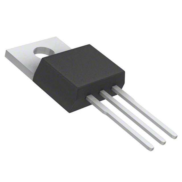
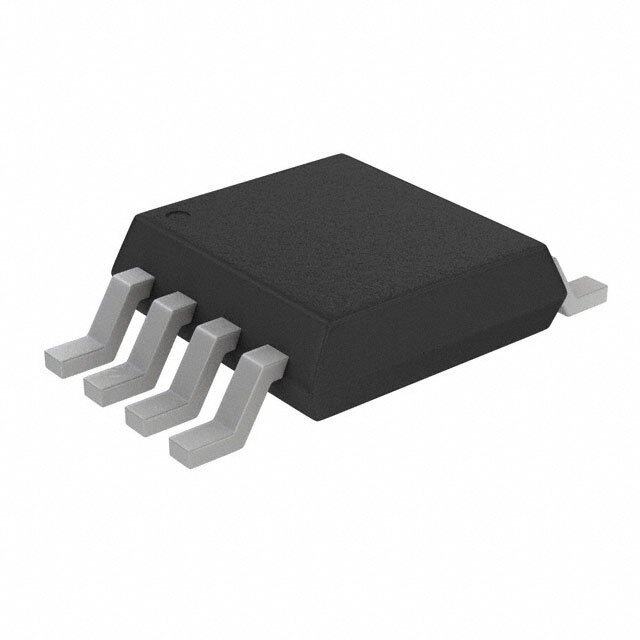
ICGOO在线商城 > 集成电路(IC) > PMIC - 稳压器 - 线性 > LP2951-33DRGR
- 型号: LP2951-33DRGR
- 制造商: Texas Instruments
- 库位|库存: xxxx|xxxx
- 要求:
| 数量阶梯 | 香港交货 | 国内含税 |
| +xxxx | $xxxx | ¥xxxx |
查看当月历史价格
查看今年历史价格
LP2951-33DRGR产品简介:
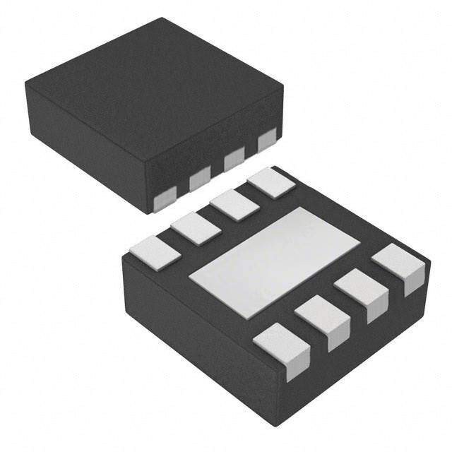
ICGOO电子元器件商城为您提供LP2951-33DRGR由Texas Instruments设计生产,在icgoo商城现货销售,并且可以通过原厂、代理商等渠道进行代购。 LP2951-33DRGR价格参考。Texas InstrumentsLP2951-33DRGR封装/规格:PMIC - 稳压器 - 线性, Linear Voltage Regulator IC 1 Output 100mA 8-SON (3x3)。您可以下载LP2951-33DRGR参考资料、Datasheet数据手册功能说明书,资料中有LP2951-33DRGR 详细功能的应用电路图电压和使用方法及教程。
| 参数 | 数值 |
| 产品目录 | 集成电路 (IC)半导体 |
| 描述 | IC REG LDO 3.3V/ADJ 0.1A 8SON低压差稳压器 Sgl Output LDO,100mA Fixed |
| 产品分类 | |
| 品牌 | Texas Instruments |
| 产品手册 | |
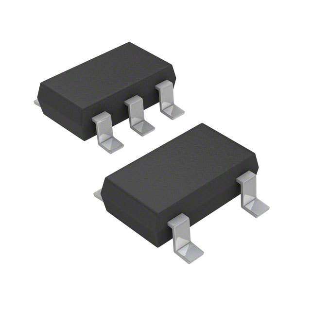
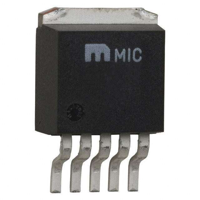
| 产品图片 |
|
| rohs | 符合RoHS无铅 / 符合限制有害物质指令(RoHS)规范要求 |
| 产品系列 | 电源管理 IC,低压差稳压器,Texas Instruments LP2951-33DRGR- |
| 数据手册 | |
| 产品型号 | LP2951-33DRGR |
| 产品种类 | 低压差稳压器 |
| 供应商器件封装 | 8-SON(3x3) |
| 其它名称 | 296-36937-1 |
| 包装 | 剪切带 (CT) |
| 商标 | Texas Instruments |
| 回动电压—最大值 | 0.08 V at 100 uA, 0.45 V at 100 mA |
| 安装类型 | 表面贴装 |
| 安装风格 | SMD/SMT |
| 封装 | Reel |
| 封装/外壳 | 8-WFDFN 裸露焊盘 |
| 封装/箱体 | WSON-8 |
| 工作温度 | -40°C ~ 125°C |
| 工厂包装数量 | 3000 |
| 最大工作温度 | + 125 C |
| 最大输入电压 | 30 V |
| 最小工作温度 | - 40 C |
| 最小输入电压 | 2 V |
| 标准包装 | 1 |
| 电压-跌落(典型值) | 0.38V @ 100mA |
| 电压-输入 | 最高 30V |
| 电压-输出 | 3.3V,1.235 V ~ 30 V |
| 电压调节准确度 | +/- 1.4 % |
| 电流-输出 | 100mA |
| 电流-限制(最小值) | - |
| 稳压器拓扑 | 正,固定式或可调式 |
| 稳压器数 | 1 |
| 系列 | LP2951-33 |
| 线路调整率 | 0.2 %/V |
| 负载调节 | 0.2 % |
| 输出电压 | 3.3 V |
| 输出电流 | 2.5 A |
| 输出端数量 | 1 Output |
| 输出类型 | Fixed |





- 商务部:美国ITC正式对集成电路等产品启动337调查
- 曝三星4nm工艺存在良率问题 高通将骁龙8 Gen1或转产台积电
- 太阳诱电将投资9.5亿元在常州建新厂生产MLCC 预计2023年完工
- 英特尔发布欧洲新工厂建设计划 深化IDM 2.0 战略
- 台积电先进制程称霸业界 有大客户加持明年业绩稳了
- 达到5530亿美元!SIA预计今年全球半导体销售额将创下新高
- 英特尔拟将自动驾驶子公司Mobileye上市 估值或超500亿美元
- 三星加码芯片和SET,合并消费电子和移动部门,撤换高东真等 CEO
- 三星电子宣布重大人事变动 还合并消费电子和移动部门
- 海关总署:前11个月进口集成电路产品价值2.52万亿元 增长14.8%



PDF Datasheet 数据手册内容提取
Product Sample & Technical Tools & Support & Folder Buy Documents Software Community LP2950,LP2951 SLVS582I–APRIL2006–REVISEDNOVEMBER2014 LP295x Adjustable Micropower Voltage Regulators with Shutdown 1 Features 2 Applications • WideInputRange:Upto30V • ApplicationswithHigh-VoltageInput 1 • RatedOutputCurrentof100mA • PowerSupplies • LowDropout:380mV(Typ)at100mA 3 Description • LowQuiescentCurrent:75 μA(Typ) The LP2950 and LP2951 devices are bipolar, low- • TightLineRegulation:0.03%(Typ) dropout voltage regulators that can accommodate a • TightLoadRegulation:0.04%(Typ) wide input supply-voltage range of up to 30 V. The • HighV Accuracy easy-to-use, 3-pin LP2950 is available in fixed-output O voltages of 5 V, 3.3 V, and 3 V. However, the 8-pin – 1.4%at25°C LP2951 is able to output either a fixed or adjustable – 2%OverTemperature output from the same device. By tying the OUTPUT • CanBeUsedasaRegulatororReference and SENSE pins together, and the FEEDBACK and V pins together, the LP2951 outputs a fixed 5 V, • StableWithLowESR(>12mΩ)Capacitors TAP 3.3 V, or 3 V (depending on the version). • Current-andThermal-LimitingFeatures Alternatively, by leaving the SENSE and V pins TAP • LP2950Only(3-PinPackage) open and connecting FEEDBACK to an external – Fixed-OutputVoltagesof5V,3.3V,and3V resistor divider, the output can be set to any value between1.235Vto30V. • LP2951Only(8-PinPackage) – Fixed-orAdjustable-OutputVoltages: DeviceInformation(1) 5V/ADJ,3.3V/ADJ,and3V/ADJ PARTNUMBER PACKAGE BODYSIZE(NOM) – Low-VoltageErrorSignalonFallingOutput LP2950 TO-92(3) 4.83mmx4.83mm – ShutdownCapability SOIC(8) 4.90mmx3.90mm LP2951 – RemoteSenseCapabilityforOptimalOutput SON(8) 3.00mmx3.00mm RegulationandAccuracy (1) For all available packages, see the orderable addendum at theendofthedatasheet. DropoutVoltagevsTemperature 500 450 V m 400 – e g 350 a olt RIL=100mA V 300 ut po 250 o r D 200 – ) UT 150 O V – 100 VIN RILL=100µA ( 50 0 -40 -25 -10 5 20 35 50 65 80 95 110 125 T –Temperature–°C A 1 An IMPORTANT NOTICE at the end of this data sheet addresses availability, warranty, changes, use in safety-critical applications, intellectualpropertymattersandotherimportantdisclaimers.PRODUCTIONDATA.
LP2950,LP2951 SLVS582I–APRIL2006–REVISEDNOVEMBER2014 www.ti.com Table of Contents 1 Features.................................................................. 1 7.3 LP2951FunctionalBlockDiagram..........................13 2 Applications........................................................... 1 7.4 FeatureDescription.................................................14 3 Description............................................................. 1 7.5 DeviceFunctionalModes........................................15 4 RevisionHistory..................................................... 2 8 ApplicationandImplementation........................ 16 8.1 ApplicationInformation............................................16 5 PinConfigurationandFunctions......................... 3 8.2 TypicalApplication .................................................16 6 Specifications......................................................... 4 9 PowerSupplyRecommendations...................... 19 6.1 AbsoluteMaximumRatings......................................4 10 Layout................................................................... 19 6.2 HandlingRatings......................................................4 6.3 RecommendedOperatingConditions.......................4 10.1 LayoutGuidelines.................................................19 6.4 ThermalInformation..................................................4 10.2 LayoutExample....................................................19 6.5 ElectricalCharacteristics...........................................5 11 DeviceandDocumentationSupport................. 19 6.6 TypicalCharacteristics..............................................7 11.1 Trademarks...........................................................19 7 DetailedDescription............................................ 12 11.2 ElectrostaticDischargeCaution............................19 7.1 Overview.................................................................12 11.3 Glossary................................................................19 7.2 LP2950FunctionalBlockDiagram..........................12 12 Mechanical,Packaging,andOrderable Information........................................................... 19 4 Revision History ChangesfromRevisionH(March2012)toRevisionI Page • AddedApplications,DeviceInformationtable,HandlingRatingstable,FeatureDescriptionsection,Device FunctionalModes,ApplicationandImplementationsection,PowerSupplyRecommendationssection,Layout section,DeviceandDocumentationSupportsection,andMechanical,Packaging,andOrderableInformationsection......1 • RemovedOrderingInformationtable..................................................................................................................................... 1 2 SubmitDocumentationFeedback Copyright©2006–2014,TexasInstrumentsIncorporated ProductFolderLinks:LP2950 LP2951
LP2950,LP2951 www.ti.com SLVS582I–APRIL2006–REVISEDNOVEMBER2014 5 Pin Configuration and Functions LP2950 LP2951 LP2951 LP PACKAGE D OR P PACKAGE DRG PACKAGE (BOTTOMVIEW) (TOPVIEW) (TOPVIEW) OUTPUT OUTPUT 1 8 INPUT OUTPUT 1 8 INPUT GND SENSE 2 7 FEEDBACK SENSE 2 Thermal 7 FEEDBACK SHUTDOWN 3 6 VTAP SHUTDOWN 3 Pad 6 VTAP INPUT GND 4 5 ERROR GND 4 5 ERROR PinFunctions PIN TYPE DESCRIPTION NAME LP2950 LP2951 Active-lowopen-collectorerroroutput.GoeslowwhenV dropsby6%ofits ERROR — 5 O OUT nominalvalue. Determinestheoutputvoltage.ConnecttoV (withOUTPUTtiedtoSENSE) TAP FEEDBACK — 7 I tooutputthefixedvoltagecorrespondingtothepartversion,orconnecttoa resistordividertoadjusttheoutputvoltage. GND 2 4 — Ground INPUT 3 8 I Supplyinput OUTPUT 1 1 O Voltageoutput. Sensestheoutputvoltage.ConnecttoOUTPUT(withFEEDBACKtiedtoV ) SENSE — 2 I TAP tooutputthevoltagecorrespondingtothepartversion. SHUTDOWN — 3 I Active-highinput.Shutsdownthedevice. V — 6 O TietoFEEDBACKtooutputthefixedvoltagecorrespondingtothepartversion. TAP Copyright©2006–2014,TexasInstrumentsIncorporated SubmitDocumentationFeedback 3 ProductFolderLinks:LP2950 LP2951
LP2950,LP2951 SLVS582I–APRIL2006–REVISEDNOVEMBER2014 www.ti.com 6 Specifications 6.1 Absolute Maximum Ratings overoperatingfree-airtemperaturerange(unlessotherwisenoted) (1) MIN MAX UNIT V Continuousinputvoltagerange –0.3 30 V IN V SHUTDOWNinputvoltagerange –1.5 30 V SHDN V ERRORcomparatoroutputvoltagerange(2) –1.5 30 V ERROR V FEEDBACKinputvoltagerange(2) (3) –1.5 30 V FDBK (1) StressesbeyondthoselistedunderAbsoluteMaximumRatingsmaycausepermanentdamagetothedevice.Thesearestressratings only,whichdonotimplyfunctionaloperationofthedeviceattheseoranyotherconditionsbeyondthoseindicatedunderRecommended OperatingConditions.Exposuretoabsolute-maximum-ratedconditionsforextendedperiodsmayaffectdevicereliability. (2) Mayexceedinputsupplyvoltage (3) Ifloadisreturnedtoanegativepowersupply,theoutputmustbediodeclampedtoGND. 6.2 Handling Ratings MIN MAX UNIT T Storagetemperaturerange –65 150 °C stg Humanbodymodel(HBM),perANSI/ESDA/JEDECJS-001,all pins(1) 0 2500 V Electrostaticdischarge V (ESD) Chargeddevicemodel(CDM),perJEDECspecification JESD22-C101,allpins(2) 0 1000 (1) JEDECdocumentJEP155statesthat500-VHBMallowssafemanufacturingwithastandardESDcontrolprocess. (2) JEDECdocumentJEP157statesthat250-VCDMallowssafemanufacturingwithastandardESDcontrolprocess. 6.3 Recommended Operating Conditions MIN MAX UNIT V Supplyinputvoltage See (1) 30 V IN T Operatingvirtualjunctiontemperature –40 125 °C J (1) MinimumV isthegreaterof: IN (a)2V(25°C),2.3V(overtemperature),or (b)V +Dropout(Max)atratedI OUT(MAX) L 6.4 Thermal Information LP2950 LP2951 THERMALMETRIC(1) LP D P DRG UNIT 3PINS 8PINS R Junction-to-ambientthermalresistance 140 97 84.6 52.44 °C/W θJA (1) Formoreinformationabouttraditionalandnewthermalmetrics,seetheICPackageThermalMetricsapplicationreport(SPRA953). 4 SubmitDocumentationFeedback Copyright©2006–2014,TexasInstrumentsIncorporated ProductFolderLinks:LP2950 LP2951
LP2950,LP2951 www.ti.com SLVS582I–APRIL2006–REVISEDNOVEMBER2014 6.5 Electrical Characteristics V =V (nominal)+1V,I =100μA,C =1μF(5-Vversions)orC =2.2μF(3-Vand3.3-Vversions), IN OUT L L L 8-pinversion:FEEDBACKtiedtoV ,OUTPUTtiedtoSENSE,V ≤0.7V TAP SHUTDOWN PARAMETER TESTCONDITIONS T MIN TYP MAX UNIT J 3-VVERSION(LP295x-30) 25°C 2.970 3 3.030 V Outputvoltage I =100μA V OUT L –40°Cto125°C 2.940 3 3.060 3.3-VVERSION(LP295x-33) 25°C 3.267 3.3 3.333 V Outputvoltage I =100μA V OUT L –40°Cto125°C 3.234 3.3 3.366 5-VVERSION(LP295x-50) 25°C 4.950 5 5.050 V Outputvoltage I =100μA V OUT L –40°Cto125°C 4.900 5 5.100 ALLVOLTAGEOPTIONS Outputvoltagetemperature coefficient(1) IL=100μA –40°Cto125°C 20 100 ppm/°C 25°C 0.03 0.2 Lineregulation(2) V =[V +1V]to30V %/V IN OUT(NOM) –40°Cto125°C 0.4 25°C 0.04% 0.2% Loadregulation(2) I =100μAto100mA — L –40°Cto125°C 0.3% 25°C 50 80 I =100μA L –40°Cto125°C 150 V –V Dropoutvoltage(3) mV IN OUT 25°C 380 450 I =100mA L –40°Cto125°C 600 25°C 75 120 I =100μA μA L –40°Cto125°C 140 I GNDcurrent GND 25°C 8 12 I =100mA mA L –40°Cto125°C 14 V =V –0.5V, 25°C 110 170 Dropoutgroundcurrent IN OUT(NOM) μA IL=100μA –40°Cto125°C 200 25°C 160 200 Currentlimit V =0V mA OUT –40°Cto125°C 220 Thermalregulation(4) I =100μA 25°C 0.05 0.2 %/W L C =1μF(5Vonly) 430 L C =200μF 160 Outputnoise(RMS), L 25°C μV 10Hzto100kHz LP2951-50:CL=3.3μF, C =0.01μFbetween 100 Bypass pins1and7 (1) Outputorreferencevoltagetemperaturecoefficientisdefinedastheworst-casevoltagechangedividedbythetotaltemperaturerange. (2) Regulationismeasuredatconstantjunctiontemperature,usingpulsetestingwithalowdutycycle.Changesinoutputvoltagedueto heatingeffectsarecoveredunderthespecificationforthermalregulation. (3) Dropoutvoltageisdefinedastheinput-to-outputdifferentialatwhichtheoutputvoltagedrops100mV,belowthevaluemeasuredat1-V differential.Theminimuminputsupplyvoltageof2V(2.3Vovertemperature)mustbeobserved. (4) Thermalregulationisdefinedasthechangeinoutputvoltageatatime(T)afterachangeinpowerdissipationisapplied,excludingload orlineregulationeffects.Specificationsarefora50-mAloadpulseatV =30V,V =5V(1.25-Wpulse)fort=10ms. IN OUT Copyright©2006–2014,TexasInstrumentsIncorporated SubmitDocumentationFeedback 5 ProductFolderLinks:LP2950 LP2951
LP2950,LP2951 SLVS582I–APRIL2006–REVISEDNOVEMBER2014 www.ti.com Electrical Characteristics (continued) V =V (nominal)+1V,I =100μA,C =1μF(5-Vversions)orC =2.2μF(3-Vand3.3-Vversions), IN OUT L L L 8-pinversion:FEEDBACKtiedtoV ,OUTPUTtiedtoSENSE,V ≤0.7V TAP SHUTDOWN PARAMETER TESTCONDITIONS T MIN TYP MAX UNIT J (LP2951-xx)8-PINVERSIONONLYADJ 25°C 1.218 1.235 1.252 –40°Cto125°C 1.212 1.257 Referencevoltage V V =V to(V –1V), OUT REF IN V =2.3Vto30V, –40°Cto125°C 1.200 1.272 IN I =100μAto100mA L Referencevoltage temperaturecoefficient(1) 25°C 20 ppm/°C 25°C 20 40 FEEDBACKbiascurrent nA –40°Cto125°C 60 FEEDBACKbiascurrent 25°C 0.1 nA/°C temperaturecoefficient ERRORCOMPARATOR 25°C 0.01 1 Outputleakagecurrent V =30V μA OUT –40°Cto125°C 2 V =V –0.5V, 25°C 150 250 Outputlowvoltage IN OUT(NOM) mV IOL=400μA –40°Cto125°C 400 Upperthresholdvoltage 25°C 40 60 (ERRORoutputhigh)(5) –40°Cto125°C 25 mV Lowerthresholdvoltage 25°C 75 95 (ERRORoutputlow)(5) –40°Cto125°C 140 mV Hysteresis(5) 25°C 15 mV SHUTDOWNINPUT Low(regulatorON) 0.7 Inputlogicvoltage –40°Cto125°C V High(regulatorOFF) 2 25°C 30 50 SHUTDOWN=2.4V –40°Cto125°C 100 SHUTDOWNinputcurrent μA 25°C 450 600 SHUTDOWN=30V –40°Cto125°C 750 V ≥2V, 25°C 3 10 Regulatoroutputcurrent SHUTDOWN V ≤30V,V =0, μA inshutdown FEINEDBACKtOieUdTtoV –40°Cto125°C 20 TAP (5) Comparatorthresholdsareexpressedintermsofavoltagedifferentialequaltothenominalreferencevoltage(measuredat V –V =1V)minusFEEDBACKterminalvoltage.Toexpressthesethresholdsintermsofoutputvoltagechange,multiplybythe IN OUT erroramplifiergain=V /V =(R1+R2)/R2.Forexample,ataprogrammedoutputvoltageof5V,theERRORoutputisspecifiedto OUT REF golowwhentheoutputdropsby95mV×5V/1.235V=384mV.ThresholdsremainconstantasapercentageofV (asV is OUT OUT varied),withthelow-outputwarningoccurringat6%belownominal(typ)and7.7%(max). 6 SubmitDocumentationFeedback Copyright©2006–2014,TexasInstrumentsIncorporated ProductFolderLinks:LP2950 LP2951
LP2950,LP2951 www.ti.com SLVS582I–APRIL2006–REVISEDNOVEMBER2014 6.6 Typical Characteristics 10 100 R =∞ L 90 80 A m 70 – 1 A Current urrent–µ 5600 scent 0.1 putC 40 uie In 30 Q 20 10 0.01 0 0.0001 0.001 0.01 0.1 0 1 2 3 4 5 6 7 8 9 10 I –LoadCurrent–A L VIN–InputVoltage–V Figure1.QuiescentCurrentvsLoadCurrent Figure2.InputCurrentvsInputVoltage(R =OPEN) L 200 120 180 RL= 50 kΩ 110 RL= 50Ω 100 160 90 140 A A 80 µ m – 120 – 70 utCurrent 18000 utCurrent 5600 Inp 60 Inp 40 30 40 20 20 10 0 0 0 1 2 3 4 5 6 7 8 9 10 0 1 2 3 4 5 6 7 8 9 10 VIN–InputVoltage–V VIN–InputVoltage–V Figure3.InputCurrentvsInputVoltage(RL=50kΩ) Figure4.InputCurrentvsInputVoltage(RL=50Ω) 5.100 120 5.075 110 IL=0 100 utVoltage–V 555...000025050 IL=100µA Current–µA 67890000 Outp 4.975 IL=100mA cent 50 – es 40 VOUT 4.950 Qui 30 20 4.925 10 4.900 0 -40 -25 -10 5 20 35 50 65 80 95 110125 0 1 2 3 4 5 6 7 8 TA–Temperature–°C VIN–InputVoltage–V Figure5.OutputVoltagevsTemperature Figure6.QuiescentCurrentvsInputVoltage(I =0) L Copyright©2006–2014,TexasInstrumentsIncorporated SubmitDocumentationFeedback 7 ProductFolderLinks:LP2950 LP2951
LP2950,LP2951 SLVS582I–APRIL2006–REVISEDNOVEMBER2014 www.ti.com Typical Characteristics (continued) 8 120 IL=100mA 110 IL=1mA 7 100 A 6 90 m –µA 80 nt– 5 urrent 6700 Curre 4 C escent 4500 escent 3 ui ui Q 30 Q 2 20 10 1 0 0 1 2 3 4 5 6 7 8 0 0 1 2 3 4 5 6 7 8 VIN–InputVoltage–V V –InputVoltage–V IN Figure7.QuiescentCurrentvsInputVoltage(IL=1mA) Figure8.QuiescentCurrentvsInputVoltage(IL=100mA) 10 100 9.5 IVLI=N=1060VmA 95 IVLI=N=1060VµA 9 90 mA 8.5 µA 85 – – Current 7.58 Current 7850 Quiescent 6.57 Quiescent 6750 6 60 5.5 55 5 50 -40 -25 -10 5 20 35 50 65 80 95 110 125 -40 -25 -10 5 20 35 50 65 80 95 110 125 TA–Temperature–°C TA–Temperature–°C Figure9.QuiescentCurrentvsTemperature(IL=100mA) Figure10.QuiescentCurrentvsTemperature(IL=100µA) 250 500 450 225 V m 400 mA 200 e– ent– 175 Voltag 330500 RIL=100mA urr ut CircuitC 112550 –Dropo 220500 ort- )OUT 150 h 100 V S – 100 75 (VIN 50 RILL=100µA 50 0 -40 -25 -10 5 20 35 50 65 80 95 110 125 -40 -25 -10 5 20 35 50 65 80 95 110125 TA–Temperature–°C TA–Temperature–°C Figure11.Short-circuitCurrentvsTemperature Figure12.DropoutVoltagevsTemperature 8 SubmitDocumentationFeedback Copyright©2006–2014,TexasInstrumentsIncorporated ProductFolderLinks:LP2950 LP2951
LP2950,LP2951 www.ti.com SLVS582I–APRIL2006–REVISEDNOVEMBER2014 Typical Characteristics (continued) 400 2 350 1.95 V m V – 300 – 1.9 Voltage 250 Voltage 1.85 ut g –Dropo 125000 Operatin 1.17.58 )OUT um V 100 m 1.7 – ni (VIN 50 Mi 1.65 0 1.6 0.0001 0.001 0.01 0.1 -40 -25 -10 5 20 35 50 65 80 95 110 125 IO–OutputCurrent–A TA–Temperature–°C Figure13.DropoutVoltagevsDropoutCurrent Figure14.LP2951MinimumOperatingVoltagevs Temperature 30 8 25 7 50-kWresistor to A 20 external 5-V supply n 6 – 15 V nt – Curre 10 utput 5 ACKBias 05 ERRORO 34 50-kWresistor B -5 to V D 2 OUT E E -10 F 1 -15 -20 0 -55 -30 -5 20 45 70 95 120 145 0 1 2 3 4 5 6 7 8 TA–Temperature–°C VIN–InputVoltage–V Figure15.LP2951FEEDBACKBiasCurrentvsTemperature Figure16.LP2951ERRORComparatorOutputvs InputVoltage 2 1.75 T = 125 A A 1.5 Input V2o Vlta/dgiev m – 1.25 Current 1 TA= 25 k n Si 0.75 – TA= –40 ISINK 0.5 Outpu8t0 VmoVlt/adgive 0.25 0 0 0.1 0.2 0.3 0.4 0.5 0.6 0.7 0.8 0.9 VOL–OutputLowVoltage–V Figure18.LineTransientResponsevsTime Figure17.LP2951ERRORComparatorSinkCurrentvs OutputLowVoltage Copyright©2006–2014,TexasInstrumentsIncorporated SubmitDocumentationFeedback 9 ProductFolderLinks:LP2950 LP2951
LP2950,LP2951 SLVS582I–APRIL2006–REVISEDNOVEMBER2014 www.ti.com Typical Characteristics (continued) Output Voltage 100 mV/div Output Load 100 mA/div Figure19.LoadTransientResponsevs Figure20.EnableTransientResponsevs Time(V =5V,C =10µF) Time(I =1mA,C =1µF) OUT L L L 100 IL=100µA 10 m h ΩO – e c n da 1 e mp IL=1mA I ut p Out 0.1 IL=100mA 0.01 1.E1+001 1.1E0+002 1.E1k+03 1.E10+k04 1.1E0+00k5 1.E1M+06 f–Frequency–Hz Figure21.EnableTransientResponsevs Time(IL=1mA,CL=10µF) Figure22.OutputImpedancevsFrequency 90 100 VIN=6V 90 CL=1µF 80 B –d dB 80 Rejection 6700 IL=0 Rejection– 6700 ple ple Rip 50 Rip 50 IL=1mA upply 40 IL=100µA Supply 40 ower-S 30 Power- 30 P VIN=6V 20 CL=1µF IL=10mA 20 10 1.E1+001 11.E0+002 1.E1+k03 1.1E0+k04 11.E0+00k5 1.E1M+06 1.E10+01 1.1E0+002 1.E1+k03 1.1E0+k04 11.E0+00k5 1.E1+M06 f–Frequency–Hz f–Frequency–Hz Figure23.RippleRejectionvsFrequency Figure24.OutputImpedancevsFrequency 10 SubmitDocumentationFeedback Copyright©2006–2014,TexasInstrumentsIncorporated ProductFolderLinks:LP2950 LP2951
LP2950,LP2951 www.ti.com SLVS582I–APRIL2006–REVISEDNOVEMBER2014 Typical Characteristics (continued) 100 6 VIN=6V 90 CL=1µF B 5 d – 80 IL=50mA n o Rejecti 6700 se–µV 4 CL=200µF ple Noi 3 pplyRip 4500 Output 2 CL=1µF Su IL=100mA wer- 30 1 o P 20 CL=3.3µF 10 0 11.E0+01 11.E00+02 1.1Ek+03 1.1E0+k04 1.1E0+00k5 1.E1+M06 1.E10+01 11.E0+002 1.1Ek+03 1.1E0+k04 11.0E0+k05 f–Frequency–Hz f–Frequency–Hz Figure25.OutputImpedancevsFrequency Figure26.LP2951OutputNoisevsFrequency 1.7 400 1.6 V Wkk 350 N)– 1.5 – O ce 300 o 1.4 n t a F Resist 250 e(OF 1.3 Pin4 200 Voltag 1.2 –Pin2to 110500 putLogic 1.11 RP2P4 50 In 0.9 0.8 0 -40 -25 -10 5 20 35 50 65 80 95 110 125 -40 -25 -10 5 20 35 50 65 80 95 110125 TA–Temperature–°C TA–Temperature–°C Figure28.ShutdownThresholdVoltage(OfftoOn)vs Temperature Figure27.LP2951DividerResistancevsTemperature 1.7 6 1.6 5 V F)– 1.5 mV 4 F ONtoO 11..34 hange– 3 Voltage( 1.2 VoltageC 12 utLogic 1.11 Output 0 p n -1 I 0.9 0.8 -2 -40 -25 -10 5 20 35 50 65 80 95 110 125 0 5 10 15 20 25 30 TA–Temperature–°C VIN–InputVoltage–V Figure29.ShutdownThresholdVoltage(OntoOff)vs Figure30.LineRegulationvsInputVoltage Temperature Copyright©2006–2014,TexasInstrumentsIncorporated SubmitDocumentationFeedback 11 ProductFolderLinks:LP2950 LP2951
LP2950,LP2951 SLVS582I–APRIL2006–REVISEDNOVEMBER2014 www.ti.com 7 Detailed Description 7.1 Overview The LP2950 and LP2951 devices are bipolar, low-dropout voltage regulators that can accommodate a wide input supply-voltage range of up to 30 V. The easy-to-use, 3-pin LP2950 is available in fixed-output voltages of 5 V, 3.3 V, and 3 V. However, the 8-pin LP2951 device is able to output either a fixed or adjustable output from the same device. By tying the OUTPUT and SENSE pins together, and the FEEDBACK and V pins together, the TAP LP2951deviceoutputsafixed5V,3.3V,or3V(dependingontheversion).Alternatively,byleavingtheSENSE and V pins open and connecting FEEDBACK to an external resistor divider, the output can be set to any TAP valuebetween1.235Vto30V. The 8-pin LP2951 device also offers additional functionality that makes it particularly suitable for battery-powered applications. For example, a logic-compatible shutdown feature allows the regulator to be put in standby mode for power savings. In addition, there is a built-in supervisor reset function in which the ERROR output goes low when V drops by 6% of its nominal value for whatever reasons – due to a drop in V , current limiting, or OUT IN thermalshutdown. The LP2950 and LP2951 devices are designed to minimize all error contributions to the output voltage. With a tight output tolerance (0.5% at 25°C), a very low output voltage temperature coefficient (20 ppm typical), extremely good line and load regulation (0.3% and 0.4% typical), and remote sensing capability, the parts can be usedaseitherlow-powervoltagereferencesor100-mAregulators. 7.2 LP2950 Functional Block Diagram INPUT OUTPUT + Error Amplifier 1.23-V Reference GND 12 SubmitDocumentationFeedback Copyright©2006–2014,TexasInstrumentsIncorporated ProductFolderLinks:LP2950 LP2951
LP2950,LP2951 www.ti.com SLVS582I–APRIL2006–REVISEDNOVEMBER2014 7.3 LP2951 Functional Block Diagram FEEDBACK INPUT OUTPUT SENSE + Error Amplifier SHUTDOWN V TAP + ERROR 60 mV 1.235-V Reference GND Copyright©2006–2014,TexasInstrumentsIncorporated SubmitDocumentationFeedback 13 ProductFolderLinks:LP2950 LP2951
LP2950,LP2951 SLVS582I–APRIL2006–REVISEDNOVEMBER2014 www.ti.com 7.4 Feature Description 7.4.1 ERROR Function(LP2951Only) The LP2951 device has a low-voltage detection comparator that outputs a logic low when the output voltage drops by ≈6% from its nominal value, and outputs a logic high when V has reached ≈95% of its nominal OUT value. This 95% of nominal figure is obtained by dividing the built-in offset of ≈60 mV by the 1.235-V bandgap reference, and remains independent of the programmed output voltage. For example, the trip-point threshold (ERROR output goes high) typically is 4.75 V for a 5-V output and 11.4 V for a 12-V output. Typically, there is a hysteresisof15mVbetweenthethresholdsforhighandlow ERROR output. A timing diagram is shown in Figure 31 for ERROR vs V (5 V), as V is ramped up and down. ERROR OUT IN becomes valid (low) when V ≈ 1.3 V. When V ≈ 5 V, V = 4.75 V, causing ERROR to go high. Because the IN IN OUT dropout voltage is load dependent, the output trip-point threshold is reached at different values of V , depending IN on the load current. For instance, at higher load current, ERROR goes high at a slightly higher value of V , and IN vice versa for lower load current. The output-voltage trip point remains at ~4.75 V, regardless of the load. Note that when V ≤ 1.3 V, the ERROR comparator output is turned off and pulled high to its pullup voltage. If V is IN OUT used as the pullup voltage, rather than an external 5-V source, ERROR typically is ~1.2 V. In this condition, an equal resistor divider (10 kΩ is suitable) can be tied to ERROR to divide down the voltage to a valid logic low duringanyfaultcondition,whilestillenablingalogichighduringnormaloperation. Output 4.75 V Voltage ERROR Input 5 V Voltage 1.3 V Figure31. ERROR OutputTiming Because the ERROR comparator has an open-collector output, an external pullup resistor is required to pull the output up to V or another supply voltage (up to 30 V). The output of the comparator is rated to sink up to OUT 400 μA. A suitable range of values for the pullup resistor is from 100 kΩ to 1 MΩ. If ERROR is not used, it can beleftopen. 14 SubmitDocumentationFeedback Copyright©2006–2014,TexasInstrumentsIncorporated ProductFolderLinks:LP2950 LP2951
LP2950,LP2951 www.ti.com SLVS582I–APRIL2006–REVISEDNOVEMBER2014 Feature Description (continued) 7.4.2 ProgrammingOutputVoltage(LP2951Only) A unique feature of the LP2951 device is its ability to output either a fixed voltage or an adjustable voltage, dependingontheexternalpinconnections.Tooutputtheinternallyprogrammedfixedvoltage,tietheSENSEpin to the OUTPUT pin and the FEEDBACK pin to the V pin. Alternatively, a user-programmable voltage ranging TAP from the internal 1.235-V reference to a 30-V max can be set by using an external resistor divider pair. The resistordivideristiedtoV ,andthedivided-downvoltageistieddirectlytoFEEDBACKforcomparisonagainst OUT the internal 1.235-V reference. To satisfy the steady-state condition in which its two inputs are equal, the error amplifierdrivestheoutputtoequalEquation1: æ R1ö V = V ´ 1+ -I R ç ÷ OUT REF è R2ø FB 1 (1) Where: V =1.235VappliedacrossR2(seeFigure32) REF I =FEEDBACKbiascurrent,typically20nA FB A minimum regulator output current of 1 μA must be maintained. Thus, in an application where a no-load condition is expected (for example, CMOS circuits in standby), this 1-μA minimum current must be provided by theresistorpair,effectivelyimposingamaximumvalueofR2=1.2MΩ (1.235V/1.2MΩ ≉ 1μA). I = 20 nA introduces an error of ≉0.02% in V . This can be offset by trimming R1. Alternatively, increasing FB OUT the divider current makes I less significant, thus, reducing its error contribution. For instance, using FB R2 = 100 kΩ reduces the error contribution of I to 0.17% by increasing the divider current to ≉12 μA. This FB increaseinthedividercurrentstillissmallcomparedtothe600-μAtypicalquiescentcurrentoftheLP2951under noload. V OUT R1 FEEDBACK R2 Figure32. AdjustingtheFeedbackontheLP2951 7.5 Device Functional Modes 7.5.1 ShutdownMode These devices can be placed in shutdown mode with a logic high at the SHUTDOWN pin. Return the logic level lowtorestoreoperationortieSHUTDOWNtogroundifthefeatureisnotbeingused. Copyright©2006–2014,TexasInstrumentsIncorporated SubmitDocumentationFeedback 15 ProductFolderLinks:LP2950 LP2951
LP2950,LP2951 SLVS582I–APRIL2006–REVISEDNOVEMBER2014 www.ti.com 8 Application and Implementation NOTE Information in the following applications sections is not part of the TI component specification, and TI does not warrant its accuracy or completeness. TI’s customers are responsible for determining suitability of components for their purposes. Customers should validateandtesttheirdesignimplementationtoconfirmsystemfunctionality. 8.1 Application Information TheLP295xdevicesareusedaslow-dropoutregulatorswithawiderangeofinputvoltages. 8.2 Typical Application 330kȍ V =5V V = 12V OUT V V IN OUT 1 8 IN 1PF SENSE 2 7 FEEDBACK 1PF LP2951-50 SHUTDOWN 3 6 VTAP GND 4 5 ERROR Figure33. 12-Vto5-VConverter 8.2.1 DesignRequirements 8.2.1.1 InputCapacitor(C ) IN A1-μF(tantalum,ceramic,oraluminum)electrolyticcapacitorshouldbeplacedlocallyattheinputoftheLP2950 or LP2951 device if there is, or will be, significant impedance between the ac filter capacitor and the input; for example, if a battery is used as the input or if the ac filter capacitor is located more than 10 in away. There are noESRrequirementsforthiscapacitor,andthecapacitancecanbeincreasedwithoutlimit. 8.2.1.2 OutputCapacitor(C ) OUT As with most PNP LDOs, stability conditions require the output capacitor to have a minimum capacitance and an ESRthatfallswithinacertainrange. 16 SubmitDocumentationFeedback Copyright©2006–2014,TexasInstrumentsIncorporated ProductFolderLinks:LP2950 LP2951
LP2950,LP2951 www.ti.com SLVS582I–APRIL2006–REVISEDNOVEMBER2014 Typical Application (continued) 8.2.2 DetailedDesignProcedure 8.2.2.1 CapacitanceValue ForV ≥5V,aminimumof1 μFisrequired.ForlowerV ,theregulator’sloopgainisrunningclosertounity OUT OUT gain and, thus, has lower phase margins. Consequently, a larger capacitance is needed for stability. For V = 3 V or 3.3 V, a minimum of 2.2 μF is recommended. For worst case, V = 1.23 V (using the ADJ OUT OUT version), a minimum of 3.3 μF is recommended. C can be increased without limit and only improves the OUT regulator stability and transient response. Regardless of its value, the output capacitor should have a resonant frequencygreaterthan500kHz. The minimum capacitance values given above are for maximum load current of 100 mA. If the maximum expectedloadcurrentislessthan100mA,thenlowervaluesofC canbeused.Forinstance,ifI <10mA, OUT OUT then only 0.33 μF is required for C . For I < 1 mA, 0.1 μF is sufficient for stability requirements. Thus, for a OUT OUT worst-case condition of 100-mA load and V = V = 1.235 V (representing the highest load current and OUT REF lowestloopgain),aminimumC of3.3μFisrecommended. OUT For the LP2950/51, no load stability is inherent in the design — a desirable feature in CMOS circuits that are put in standby (such as RAM keep-alive applications). If the LP2951 is used with external resistors to set the output voltage,aminimumloadcurrentof1μAisrecommendedthroughtheresistordivider. 8.2.2.2 CapacitorTypes Most tantalum or aluminum electrolytics are suitable for use at the input. Film-type capacitors also work but at higher cost. When operating at low temperature, care should be taken with aluminum electrolytics, as their electrolytes often freeze at –30°C. For this reason, solid tantalum capacitors should be used at temperatures below–25°C. Ceramic capacitors can be used, but due to their low ESR (as low as 5 mΩ to 10 mΩ), they may not meet the minimum ESR requirement previously discussed. If a ceramic capacitor is used, a series resistor between 0.1 Ω to 2 Ω must be added to meet the minimum ESR requirement. In addition, ceramic capacitors have one glaring disadvantage that must be taken into account — a poor temperature coefficient, where the capacitance can vary significantly with temperature. For instance, a large-value ceramic capacitor (≥ 2.2 μF) can lose more than half of its capacitance as temperature rises from 25°C to 85°C. Thus, a 2.2-μF capacitor at 25°C drops well below the minimum C required for stability as ambient temperature rises. For this reason, select an output OUT capacitorthatmaintainstheminimum2.2μFrequiredforstabilityfortheentireoperatingtemperaturerange. 8.2.2.3 C :NoiseandStabilityImprovement BYPASS In the LP2951 device, an external FEEDBACK pin directly connected to the error amplifier noninverting input can allow stray capacitance to cause instability by shunting the error amplifier feedback to GND, especially at high frequencies. This is worsened if high-value external resistors are used to set the output voltage, because a high resistance allows the stray capacitance to play a more significant role; i.e., a larger RC time delay is introduced between the output of the error amplifier and its FEEDBACK input, leading to more phase shift and lower phase margin. A solution is to add a 100-pF bypass capacitor (C ) between OUTPUT and FEEDBACK; because BYPASS C is in parallel with R1, it lowers the impedance seen at FEEDBACK at high frequencies, in effect BYPASS offsetting the effect of the parasitic capacitance by providing more feedback at higher frequencies. More feedback forces the error amplifier to work at a lower loop gain, so C should be increased to a minimum of OUT 3.3 μFtoimprovetheregulator’sphasemargin. C can be also used to reduce output noise in the LP2951 device. This bypass capacitor reduces the BYPASS closed loop gain of the error amplifier at the high frequency, so noise no longer scales with the output voltage. This improvement is more noticeable with higher output voltages, where loop gain reduction is greatest. A suitableC iscalculatedasshowninEquation2: BYPASS 1 f ; 200Hz®C = (CBYPASS) (BYPASS) 2p´R1´200Hz (2) On the 3-pin LP2950 device, noise reduction can be achieved by increasing the output capacitor, which causes the regulator bandwidth to be reduced, thus eliminating high-frequency noise. However, this method is relatively inefficient, as increasing C from 1 μF to 220 μF only reduces the regulator’s output noise from OUT 430μVto160 μV(overa100-kHzbandwidth). Copyright©2006–2014,TexasInstrumentsIncorporated SubmitDocumentationFeedback 17 ProductFolderLinks:LP2950 LP2951
LP2950,LP2951 SLVS582I–APRIL2006–REVISEDNOVEMBER2014 www.ti.com Typical Application (continued) 8.2.2.4 ESRRange The regulator control loop relies on the ESR of the output capacitor to provide a zero to add sufficient phase margin to ensure unconditional regulator stability; this requires the closed-loop gain to intersect the open-loop response in a region where the open-loop gain rolls off at 20 dB/decade. This ensures that the phase is always less than 180° (phase margin greater than 0°) at unity gain. Thus, a minimum-maximum range for the ESR must beobserved. The upper limit of this ESR range is established by the fact that an ESR that is too high could result in the zero occurring too soon, causing the gain to roll off too slowly. This, in turn, allows a third pole to appear before unity gain and introduces enough phase shift to cause instability. This typically limits the maximum ESR to approximately5 Ω. Conversely, the lower limit of the ESR range is tied to the fact that an ESR that is too low shifts the zero too far out, past unity gain, which allows the gain to roll off at 40 dB/decade at unity gain, resulting in a phase shift of greaterthan180°.Typically,thislimitstheminimumESRtoapproximately20mΩ to30mΩ. ForspecificESRrequirements,seeTypicalCharacteristics. 8.2.3 ApplicationCurves Output Voltage 100 mV/div Output Load 100 mA/div Figure34.LoadTransientResponsevsTime(V =5V,C =1µF) OUT L 18 SubmitDocumentationFeedback Copyright©2006–2014,TexasInstrumentsIncorporated ProductFolderLinks:LP2950 LP2951
LP2950,LP2951 www.ti.com SLVS582I–APRIL2006–REVISEDNOVEMBER2014 9 Power Supply Recommendations Maximuminputvoltageshouldbelimitedto30Vforproperoperation.Placeinputandoutputcapacitorsasclose tothedeviceaspossibletotakeadvantageoftheirhighfrequencynoisefilteringproperties. 10 Layout 10.1 Layout Guidelines • Make sure that traces on the input and outputs of the device are wide enough to handle the desired currents. Forthisdevice,theoutputtracewillneedtobelargerinordertoaccommodatethelargeravailablecurrent. • Placeinputandoutputcapacitorsasclosetothedeviceaspossibletotakeadvantageoftheirhighfrequency noisefilteringproperties. 10.2 Layout Example 1 8 2 7 1 PF 1 PF LP2951-50 3 6 4 5 ERROR can be left floating if not used Figure35. LP2951LayoutExample(DorPPackage) 11 Device and Documentation Support 11.1 Trademarks Alltrademarksarethepropertyoftheirrespectiveowners. 11.2 Electrostatic Discharge Caution Thesedeviceshavelimitedbuilt-inESDprotection.Theleadsshouldbeshortedtogetherorthedeviceplacedinconductivefoam duringstorageorhandlingtopreventelectrostaticdamagetotheMOSgates. 11.3 Glossary SLYZ022—TIGlossary. Thisglossarylistsandexplainsterms,acronyms,anddefinitions. 12 Mechanical, Packaging, and Orderable Information The following pages include mechanical, packaging, and orderable information. This information is the most current data available for the designated devices. This data is subject to change without notice and revision of thisdocument.Forbrowser-basedversionsofthisdatasheet,refertotheleft-handnavigation. Copyright©2006–2014,TexasInstrumentsIncorporated SubmitDocumentationFeedback 19 ProductFolderLinks:LP2950 LP2951
PACKAGE OPTION ADDENDUM www.ti.com 27-Mar-2019 PACKAGING INFORMATION Orderable Device Status Package Type Package Pins Package Eco Plan Lead/Ball Finish MSL Peak Temp Op Temp (°C) Device Marking Samples (1) Drawing Qty (2) (6) (3) (4/5) LP2950-30LP ACTIVE TO-92 LP 3 1000 Pb-Free CU SN N / A for Pkg Type -40 to 125 KY5030 (RoHS) LP2950-30LPR ACTIVE TO-92 LP 3 2000 Pb-Free CU SN N / A for Pkg Type -40 to 125 KY5030 (RoHS) LP2950-30LPRE3 ACTIVE TO-92 LP 3 2000 Pb-Free CU SN N / A for Pkg Type -40 to 125 KY5030 (RoHS) LP2950-33LPE3 ACTIVE TO-92 LP 3 1000 Pb-Free CU SN N / A for Pkg Type -40 to 125 KY5033 (RoHS) LP2950-33LPRE3 ACTIVE TO-92 LP 3 2000 Pb-Free CU SN N / A for Pkg Type -40 to 125 KY5033 (RoHS) LP2950-50LPRE3 ACTIVE TO-92 LP 3 2000 Pb-Free CU SN N / A for Pkg Type -40 to 125 KY5050 (RoHS) LP2951-30D ACTIVE SOIC D 8 75 Green (RoHS CU NIPDAU Level-1-260C-UNLIM -40 to 125 KY5130 & no Sb/Br) LP2951-30DR ACTIVE SOIC D 8 2500 Green (RoHS CU NIPDAU Level-1-260C-UNLIM -40 to 125 KY5130 & no Sb/Br) LP2951-30DRGR ACTIVE SON DRG 8 3000 Green (RoHS CU NIPDAU Level-2-260C-1 YEAR -40 to 125 ZUD & no Sb/Br) LP2951-33D ACTIVE SOIC D 8 75 Green (RoHS CU NIPDAU Level-1-260C-UNLIM -40 to 125 KY5133 & no Sb/Br) LP2951-33DR ACTIVE SOIC D 8 2500 Green (RoHS CU NIPDAU Level-1-260C-UNLIM -40 to 125 KY5133 & no Sb/Br) LP2951-33DRG4 ACTIVE SOIC D 8 2500 Green (RoHS CU NIPDAU Level-1-260C-UNLIM -40 to 125 KY5133 & no Sb/Br) LP2951-33DRGR ACTIVE SON DRG 8 3000 Green (RoHS CU NIPDAU Level-2-260C-1 YEAR -40 to 125 ZUE & no Sb/Br) LP2951-50D ACTIVE SOIC D 8 75 Green (RoHS CU NIPDAU Level-1-260C-UNLIM -40 to 125 KY5150 & no Sb/Br) LP2951-50DR ACTIVE SOIC D 8 2500 Green (RoHS CU NIPDAU Level-1-260C-UNLIM -40 to 125 KY5150 & no Sb/Br) LP2951-50DRG4 ACTIVE SOIC D 8 2500 Green (RoHS CU NIPDAU Level-1-260C-UNLIM -40 to 125 KY5150 & no Sb/Br) LP2951-50DRGR ACTIVE SON DRG 8 3000 Green (RoHS CU NIPDAU Level-2-260C-1 YEAR -40 to 125 ZUF & no Sb/Br) Addendum-Page 1
PACKAGE OPTION ADDENDUM www.ti.com 27-Mar-2019 Orderable Device Status Package Type Package Pins Package Eco Plan Lead/Ball Finish MSL Peak Temp Op Temp (°C) Device Marking Samples (1) Drawing Qty (2) (6) (3) (4/5) LP2951D ACTIVE SOIC D 8 75 Green (RoHS CU NIPDAU Level-1-260C-UNLIM -40 to 125 LP2951 & no Sb/Br) LP2951DR ACTIVE SOIC D 8 2500 Green (RoHS CU NIPDAU Level-1-260C-UNLIM -40 to 125 LP2951 & no Sb/Br) LP2951DRG4 ACTIVE SOIC D 8 2500 Green (RoHS CU NIPDAU Level-1-260C-UNLIM -40 to 125 LP2951 & no Sb/Br) (1) The marketing status values are defined as follows: ACTIVE: Product device recommended for new designs. LIFEBUY: TI has announced that the device will be discontinued, and a lifetime-buy period is in effect. NRND: Not recommended for new designs. Device is in production to support existing customers, but TI does not recommend using this part in a new design. PREVIEW: Device has been announced but is not in production. Samples may or may not be available. OBSOLETE: TI has discontinued the production of the device. (2) RoHS: TI defines "RoHS" to mean semiconductor products that are compliant with the current EU RoHS requirements for all 10 RoHS substances, including the requirement that RoHS substance do not exceed 0.1% by weight in homogeneous materials. Where designed to be soldered at high temperatures, "RoHS" products are suitable for use in specified lead-free processes. TI may reference these types of products as "Pb-Free". RoHS Exempt: TI defines "RoHS Exempt" to mean products that contain lead but are compliant with EU RoHS pursuant to a specific EU RoHS exemption. Green: TI defines "Green" to mean the content of Chlorine (Cl) and Bromine (Br) based flame retardants meet JS709B low halogen requirements of <=1000ppm threshold. Antimony trioxide based flame retardants must also meet the <=1000ppm threshold requirement. (3) MSL, Peak Temp. - The Moisture Sensitivity Level rating according to the JEDEC industry standard classifications, and peak solder temperature. (4) There may be additional marking, which relates to the logo, the lot trace code information, or the environmental category on the device. (5) Multiple Device Markings will be inside parentheses. Only one Device Marking contained in parentheses and separated by a "~" will appear on a device. If a line is indented then it is a continuation of the previous line and the two combined represent the entire Device Marking for that device. (6) Lead/Ball Finish - Orderable Devices may have multiple material finish options. Finish options are separated by a vertical ruled line. Lead/Ball Finish values may wrap to two lines if the finish value exceeds the maximum column width. Important Information and Disclaimer:The information provided on this page represents TI's knowledge and belief as of the date that it is provided. TI bases its knowledge and belief on information provided by third parties, and makes no representation or warranty as to the accuracy of such information. Efforts are underway to better integrate information from third parties. TI has taken and continues to take reasonable steps to provide representative and accurate information but may not have conducted destructive testing or chemical analysis on incoming materials and chemicals. TI and TI suppliers consider certain information to be proprietary, and thus CAS numbers and other limited information may not be available for release. In no event shall TI's liability arising out of such information exceed the total purchase price of the TI part(s) at issue in this document sold by TI to Customer on an annual basis. Addendum-Page 2
PACKAGE OPTION ADDENDUM www.ti.com 27-Mar-2019 OTHER QUALIFIED VERSIONS OF LP2951 : •Automotive: LP2951-Q1 NOTE: Qualified Version Definitions: •Automotive - Q100 devices qualified for high-reliability automotive applications targeting zero defects Addendum-Page 3
PACKAGE MATERIALS INFORMATION www.ti.com 10-Jun-2017 TAPE AND REEL INFORMATION *Alldimensionsarenominal Device Package Package Pins SPQ Reel Reel A0 B0 K0 P1 W Pin1 Type Drawing Diameter Width (mm) (mm) (mm) (mm) (mm) Quadrant (mm) W1(mm) LP2951-30DR SOIC D 8 2500 330.0 12.4 6.4 5.2 2.1 8.0 12.0 Q1 LP2951-30DRGR SON DRG 8 3000 330.0 12.4 3.3 3.3 1.1 8.0 12.0 Q2 LP2951-33DR SOIC D 8 2500 330.0 12.4 6.4 5.2 2.1 8.0 12.0 Q1 LP2951-33DRGR SON DRG 8 3000 330.0 12.4 3.3 3.3 1.1 8.0 12.0 Q2 LP2951-50DR SOIC D 8 2500 330.0 12.4 6.4 5.2 2.1 8.0 12.0 Q1 LP2951-50DRGR SON DRG 8 3000 330.0 12.4 3.3 3.3 1.1 8.0 12.0 Q2 LP2951DR SOIC D 8 2500 330.0 12.4 6.4 5.2 2.1 8.0 12.0 Q1 PackMaterials-Page1
PACKAGE MATERIALS INFORMATION www.ti.com 10-Jun-2017 *Alldimensionsarenominal Device PackageType PackageDrawing Pins SPQ Length(mm) Width(mm) Height(mm) LP2951-30DR SOIC D 8 2500 340.5 338.1 20.6 LP2951-30DRGR SON DRG 8 3000 367.0 367.0 35.0 LP2951-33DR SOIC D 8 2500 340.5 338.1 20.6 LP2951-33DRGR SON DRG 8 3000 367.0 367.0 35.0 LP2951-50DR SOIC D 8 2500 340.5 338.1 20.6 LP2951-50DRGR SON DRG 8 3000 367.0 367.0 35.0 LP2951DR SOIC D 8 2500 340.5 338.1 20.6 PackMaterials-Page2
PACKAGE OUTLINE D0008A SOIC - 1.75 mm max height SCALE 2.800 SMALL OUTLINE INTEGRATED CIRCUIT C SEATING PLANE .228-.244 TYP [5.80-6.19] .004 [0.1] C A PIN 1 ID AREA 6X .050 [1.27] 8 1 2X .189-.197 [4.81-5.00] .150 NOTE 3 [3.81] 4X (0 -15 ) 4 5 8X .012-.020 B .150-.157 [0.31-0.51] .069 MAX [3.81-3.98] .010 [0.25] C A B [1.75] NOTE 4 .005-.010 TYP [0.13-0.25] 4X (0 -15 ) SEE DETAIL A .010 [0.25] .004-.010 0 - 8 [0.11-0.25] .016-.050 [0.41-1.27] DETAIL A (.041) TYPICAL [1.04] 4214825/C 02/2019 NOTES: 1. Linear dimensions are in inches [millimeters]. Dimensions in parenthesis are for reference only. Controlling dimensions are in inches. Dimensioning and tolerancing per ASME Y14.5M. 2. This drawing is subject to change without notice. 3. This dimension does not include mold flash, protrusions, or gate burrs. Mold flash, protrusions, or gate burrs shall not exceed .006 [0.15] per side. 4. This dimension does not include interlead flash. 5. Reference JEDEC registration MS-012, variation AA. www.ti.com
EXAMPLE BOARD LAYOUT D0008A SOIC - 1.75 mm max height SMALL OUTLINE INTEGRATED CIRCUIT 8X (.061 ) [1.55] SYMM SEE DETAILS 1 8 8X (.024) [0.6] SYMM (R.002 ) TYP [0.05] 5 4 6X (.050 ) [1.27] (.213) [5.4] LAND PATTERN EXAMPLE EXPOSED METAL SHOWN SCALE:8X SOLDER MASK SOLDER MASK METAL OPENING OPENING METAL UNDER SOLDER MASK EXPOSED METAL EXPOSED METAL .0028 MAX .0028 MIN [0.07] [0.07] ALL AROUND ALL AROUND NON SOLDER MASK SOLDER MASK DEFINED DEFINED SOLDER MASK DETAILS 4214825/C 02/2019 NOTES: (continued) 6. Publication IPC-7351 may have alternate designs. 7. Solder mask tolerances between and around signal pads can vary based on board fabrication site. www.ti.com
EXAMPLE STENCIL DESIGN D0008A SOIC - 1.75 mm max height SMALL OUTLINE INTEGRATED CIRCUIT 8X (.061 ) [1.55] SYMM 1 8 8X (.024) [0.6] SYMM (R.002 ) TYP [0.05] 5 4 6X (.050 ) [1.27] (.213) [5.4] SOLDER PASTE EXAMPLE BASED ON .005 INCH [0.125 MM] THICK STENCIL SCALE:8X 4214825/C 02/2019 NOTES: (continued) 8. Laser cutting apertures with trapezoidal walls and rounded corners may offer better paste release. IPC-7525 may have alternate design recommendations. 9. Board assembly site may have different recommendations for stencil design. www.ti.com
None
None
None
None
PACKAGE OUTLINE LP0003A TO-92 - 5.34 mm max height SCALE 1.200 SCALE 1.200 TO-92 5.21 4.44 EJECTOR PIN OPTIONAL 5.34 4.32 (1.5) TYP (2.54) SEATING 2X NOTE 3 PLANE 4 MAX (0.51) TYP 6X 0.076 MAX SEATING PLANE 3X 12.7 MIN 0.43 2X 0.55 3X 3X 0.35 2.6 0.2 0.38 2X 1.27 0.13 FORMED LEAD OPTION OTHER DIMENSIONS IDENTICAL STRAIGHT LEAD OPTION TO STRAIGHT LEAD OPTION 2.67 3X 2.03 4.19 3.17 3 2 1 3.43 MIN 4215214/B 04/2017 NOTES: 1. All linear dimensions are in millimeters. Any dimensions in parenthesis are for reference only. Dimensioning and tolerancing per ASME Y14.5M. 2. This drawing is subject to change without notice. 3. Lead dimensions are not controlled within this area. 4. Reference JEDEC TO-226, variation AA. 5. Shipping method: a. Straight lead option available in bulk pack only. b. Formed lead option available in tape and reel or ammo pack. c. Specific products can be offered in limited combinations of shipping medium and lead options. d. Consult product folder for more information on available options. www.ti.com
EXAMPLE BOARD LAYOUT LP0003A TO-92 - 5.34 mm max height TO-92 FULL R TYP 0.05 MAX (1.07) ALL AROUND METAL 3X ( 0.85) HOLE TYP TYP 2X METAL (1.5) 2X (1.5) 2X SOLDER MASK OPENING 1 2 3 (R0.05) TYP 2X (1.07) (1.27) SOLDER MASK (2.54) OPENING LAND PATTERN EXAMPLE STRAIGHT LEAD OPTION NON-SOLDER MASK DEFINED SCALE:15X 0.05 MAX ( 1.4) 2X ( 1.4) ALL AROUND METAL TYP 3X ( 0.9) HOLE METAL 2X (R0.05) TYP 1 2 3 SOLDER MASK OPENING (2.6) SOLDER MASK OPENING (5.2) LAND PATTERN EXAMPLE FORMED LEAD OPTION NON-SOLDER MASK DEFINED SCALE:15X 4215214/B 04/2017 www.ti.com
TAPE SPECIFICATIONS LP0003A TO-92 - 5.34 mm max height TO-92 13.7 11.7 32 23 (2.5) TYP 0.5 MIN 16.5 15.5 11.0 9.75 8.5 8.50 19.0 17.5 2.9 6.75 3.7-4.3 TYP TYP 2.4 5.95 13.0 12.4 FOR FORMED LEAD OPTION PACKAGE 4215214/B 04/2017 www.ti.com
IMPORTANTNOTICEANDDISCLAIMER TIPROVIDESTECHNICALANDRELIABILITYDATA(INCLUDINGDATASHEETS),DESIGNRESOURCES(INCLUDINGREFERENCE DESIGNS),APPLICATIONOROTHERDESIGNADVICE,WEBTOOLS,SAFETYINFORMATION,ANDOTHERRESOURCES“ASIS” ANDWITHALLFAULTS,ANDDISCLAIMSALLWARRANTIES,EXPRESSANDIMPLIED,INCLUDINGWITHOUTLIMITATIONANY IMPLIEDWARRANTIESOFMERCHANTABILITY,FITNESSFORAPARTICULARPURPOSEORNON-INFRINGEMENTOFTHIRD PARTYINTELLECTUALPROPERTYRIGHTS. TheseresourcesareintendedforskilleddevelopersdesigningwithTIproducts.Youaresolelyresponsiblefor(1)selectingtheappropriate TIproductsforyourapplication,(2)designing,validatingandtestingyourapplication,and(3)ensuringyourapplicationmeetsapplicable standards,andanyothersafety,security,orotherrequirements.Theseresourcesaresubjecttochangewithoutnotice.TIgrantsyou permissiontousetheseresourcesonlyfordevelopmentofanapplicationthatusestheTIproductsdescribedintheresource.Other reproductionanddisplayoftheseresourcesisprohibited.NolicenseisgrantedtoanyotherTIintellectualpropertyrightortoanythird partyintellectualpropertyright.TIdisclaimsresponsibilityfor,andyouwillfullyindemnifyTIanditsrepresentativesagainst,anyclaims, damages,costs,losses,andliabilitiesarisingoutofyouruseoftheseresources. TI’sproductsareprovidedsubjecttoTI’sTermsofSale(www.ti.com/legal/termsofsale.html)orotherapplicabletermsavailableeitheron ti.comorprovidedinconjunctionwithsuchTIproducts.TI’sprovisionoftheseresourcesdoesnotexpandorotherwisealterTI’sapplicable warrantiesorwarrantydisclaimersforTIproducts. MailingAddress:TexasInstruments,PostOfficeBox655303,Dallas,Texas75265 Copyright©2019,TexasInstrumentsIncorporated
 Datasheet下载


