ICGOO在线商城 > 开发板,套件,编程器 > 评估板 - DC/DC 与 AC/DC(离线)SMPS > LM5113LLPEVB/NOPB
- 型号: LM5113LLPEVB/NOPB
- 制造商: Texas Instruments
- 库位|库存: xxxx|xxxx
- 要求:
| 数量阶梯 | 香港交货 | 国内含税 |
| +xxxx | $xxxx | ¥xxxx |
查看当月历史价格
查看今年历史价格
LM5113LLPEVB/NOPB产品简介:
ICGOO电子元器件商城为您提供LM5113LLPEVB/NOPB由Texas Instruments设计生产,在icgoo商城现货销售,并且可以通过原厂、代理商等渠道进行代购。 LM5113LLPEVB/NOPB价格参考¥1130.14-¥1130.14。Texas InstrumentsLM5113LLPEVB/NOPB封装/规格:评估板 - DC/DC 与 AC/DC(离线)SMPS, LM5113 - DC/DC, Step Down 1, Non-Isolated Outputs Evaluation Board。您可以下载LM5113LLPEVB/NOPB参考资料、Datasheet数据手册功能说明书,资料中有LM5113LLPEVB/NOPB 详细功能的应用电路图电压和使用方法及教程。
| 参数 | 数值 |
| 产品目录 | 编程器,开发系统半导体 |
| 描述 | BOARD EVAL FOR LM5113LLP电源管理IC开发工具 LM5113 Eval Brd |
| 产品分类 | |
| 品牌 | Texas Instruments |
| 产品手册 | |
| 产品图片 |
|
| rohs | 符合RoHS含铅 / 不符合限制有害物质指令(RoHS)规范要求 |
| 产品系列 | 电源管理IC开发工具,Texas Instruments LM5113LLPEVB/NOPB- |
| 数据手册 | 点击此处下载产品Datasheethttp://www.ti.com/lit/pdf/snva484 |
| 产品型号 | LM5113LLPEVB/NOPB |
| 主要用途 | DC/DC,步降 |
| 产品 | Evaluation Boards |
| 产品种类 | 电源管理IC开发工具 |
| 使用的IC/零件 | LM5113 |
| 其它名称 | LM5113LLPEVBNOPB |
| 功率-输出 | - |
| 参考设计库 | http://designs.digikey.com/library/4294959904/4294959903/940 |
| 商标 | Texas Instruments |
| 工具用于评估 | LM5113 |
| 工厂包装数量 | 1 |
| 所含物品 | 板 |
| 描述/功能 | Synchronous Buck Converter |
| 板类型 | 完全填充 |
| 标准包装 | 1 |
| 电压-输入 | 15 V ~ 60 V |
| 电压-输出 | 10V |
| 电流-输出 | 10A |
| 相关产品 | /product-detail/zh/LM5113TME%2FNOPB/296-36000-6-ND/4135118/product-detail/zh/LM5113TME%2FNOPB/296-36000-1-ND/4135105/product-detail/zh/LM5113TMX%2FNOPB/LM5113TMX%2FNOPB-ND/3179205/product-detail/zh/LM5113TME%2FNOPB/296-36000-2-ND/3179204/product-detail/zh/LM5113SDX%2FNOPB/LM5113SDX%2FNOPB-ND/3179158/product-detail/zh/LM5113SDE%2FNOPB/LM5113SDE%2FNOPBDKR-ND/3026100/product-detail/zh/LM5113SDE%2FNOPB/LM5113SDE%2FNOPBCT-ND/3026099/product-detail/zh/LM5113SDE%2FNOPB/LM5113SDE%2FNOPBTR-ND/3026076/product-detail/zh/LM5113SD%2FNOPB/LM5113SD%2FNOPBDKR-ND/2777087/product-detail/zh/LM5113SD%2FNOPB/LM5113SD%2FNOPBCT-ND/2777073/product-detail/zh/LM5113SD%2FNOPB/LM5113SD%2FNOPBTR-ND/2777059 |
| 稳压器拓扑 | 降压 |
| 类型 | Gate Drivers |
| 输入电压 | 15 V to 60 V |
| 输出和类型 | 1,非隔离 |
| 输出电压 | 10 V |
| 输出电流 | 10 A |
| 频率-开关 | 800kHz |



- 商务部:美国ITC正式对集成电路等产品启动337调查
- 曝三星4nm工艺存在良率问题 高通将骁龙8 Gen1或转产台积电
- 太阳诱电将投资9.5亿元在常州建新厂生产MLCC 预计2023年完工
- 英特尔发布欧洲新工厂建设计划 深化IDM 2.0 战略
- 台积电先进制程称霸业界 有大客户加持明年业绩稳了
- 达到5530亿美元!SIA预计今年全球半导体销售额将创下新高
- 英特尔拟将自动驾驶子公司Mobileye上市 估值或超500亿美元
- 三星加码芯片和SET,合并消费电子和移动部门,撤换高东真等 CEO
- 三星电子宣布重大人事变动 还合并消费电子和移动部门
- 海关总署:前11个月进口集成电路产品价值2.52万亿元 增长14.8%
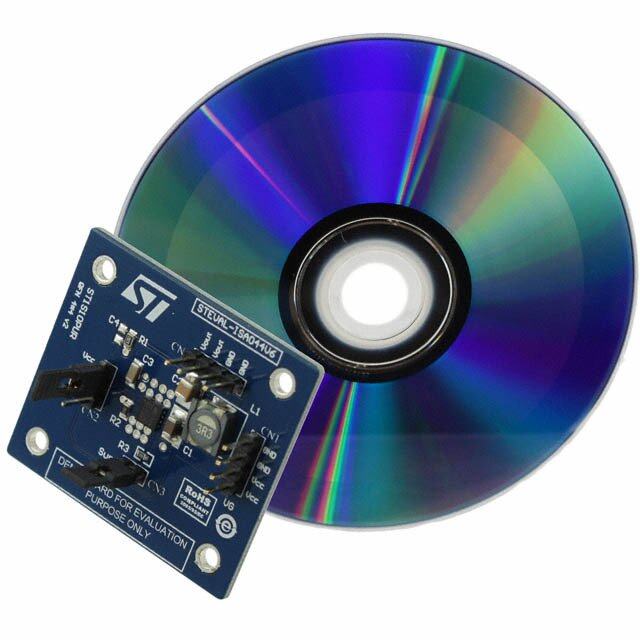
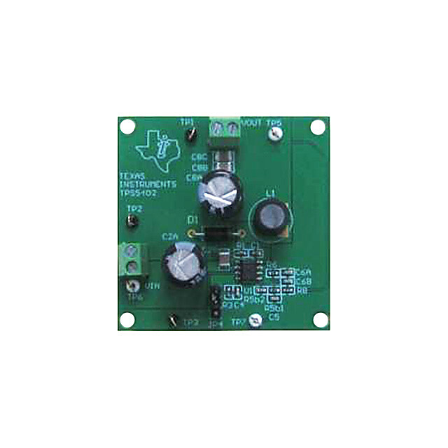
PDF Datasheet 数据手册内容提取
User's Guide SNVA484A–October2011–RevisedMay2013 AN-2149 LM5113 Evaluation Board 1 Introduction TheLM5113evaluationboardisdesignedtoprovidethedesignengineerswithasynchronousbuck convertertoevaluatetheLM5113,a100Vhalf-bridgeenhancementmodeGalliumNitride(GaN)FET driver.TheactiveclampingvoltagemodecontrollerLM5025isusedtogeneratethePWMsignalsofthe buckswitchandthesynchronousswitch.Thespecificationsoftheevaluationboardareasfollows: • InputOperatingVoltage:15Vto60V • OutputVoltage:10V • OutputCurrent:10A@48V,7A@60V • MeasuredEfficiencyat48V:93.9%@10A • FrequencyofOperation:800kHz • LineUVLO:13.8V(Rising)/10.8V(Falling) • Boardsize:3.00x2.83inches Theprintedcircuitboard(PCB)consistsof2layersof2ouncecopperonFR4material,withathicknessof 0.050inches. Thisdocumentcontainstheschematicoftheevaluationboard,BillofMaterials(BOM)andaquicksetup procedure.Theevaluationboardcanbereconfiguredfordifferentswitchingfrequency,deadtime,andthe outputvoltagefromthespecificationsabove.Anexampleof48Vto3.3Vconversionisgivenin AppendixA.Formorecompleteinformation,seetheLM51135A,100VHalf-BridgeGateDriverfor EnhancementModeGaNFETsDataSheet(SNVS725) 2 IC Features • Independenthigh-sideandlow-sideTTLlogicinputs • 1.2A/5Apeaksource/sinkcurrent • High-sidefloatingbiasvoltagerailoperatesupto100VDC • Internalbootstrapsupplyvoltageclamping • Splitoutputsforadjustableturn-on/turn-offstrength • 0.6Ω/2.1Ω pull-down/pull-upresistance • Fastpropagationtimes(28nstypical) • Excellentpropagationdelaymatching(1.5nstypical) • Supplyrailunder-voltagelockout • Lowpowerconsumption 3 Powering and Loading Considerations CertainprecautionsneedtobefollowedwhenapplyingpowertotheLM5113evaluationboard.A misconnectioncandamagetheassembly. Alltrademarksarethepropertyoftheirrespectiveowners. SNVA484A–October2011–RevisedMay2013 AN-2149LM5113EvaluationBoard 1 SubmitDocumentationFeedback Copyright©2011–2013,TexasInstrumentsIncorporated
PoweringandLoadingConsiderations www.ti.com 3.1 Proper Board Connection Figure2depictsthetypicalevaluationsetup.ThesourcepowerisconnectedtotheJ1(VIN)andtheJ3 (GND).TheloadisconnectedtotheJ2(VOUT)andtheJ4(GND).Besuretochoosethecorrect connectorandwiresize.Theinputandoutputvoltagemustbemonitoreddirectlyattheterminalsofthe board.Thevoltagedropacrosstheconnectionwireswillcauseinaccuratemeasurements. HB UVLO & CLAMP HOH LEVEL HOL SHIFT HS HI VDD UVLO LOH LOL LI VSS Figure1.SimplifiedBlockDiagramofLM5113 Current Meter J1 VIN + LM5113 EVAL DC Power Supply J3 GND - J4 J2 GND VOUT Volt-meter + Electronic Load with current meter - Figure2.TypicalEvaluationSetup 3.2 Source Power TofullytesttheLM5113evaluationboard,aDCpowersupplycapableof60Vand8Aisrequired.The powersupplyandcablingmustpresentlowimpedancetotheevaluationboard.Insufficientcablingora highimpedancepowersupplywilldroopduringpowersupplyapplicationwiththeevaluationboardinrush current.Iflargeenough,thisdroopwillcauseachatteringconditionuponpowerup.Thischattering conditionisaninteractionwiththeevaluationboardundervoltagelockout,thecablingimpedanceandthe inrushcurrent. 2 AN-2149LM5113EvaluationBoard SNVA484A–October2011–RevisedMay2013 SubmitDocumentationFeedback Copyright©2011–2013,TexasInstrumentsIncorporated
www.ti.com PoweringandLoadingConsiderations 3.3 Output Current Derating TheLM5113evaluationboardisdesignedtooperatewithamaximumloadcurrentof10Aforinput voltagesrangingfrom15Vto48V.Withfurtherincreasesoftheinputvoltage,themaximumallowableload currentgraduallydecreasesto7A,toensurereliableprolongedoperation.Figure3illustratesthederating curveoftheoutputcurrentatroomtemperaturewithairflowof200CFM.Itmaybenecessarytofurther reducethemaximumloadcurrentathigherambienttemperature. NotethattheLM5113evaluationboarddoesnothaveovercurrentprotection.Certainprecautionsshould betakentopreventtheloadcurrentfromexceedingthederatingcurveshowninFigure3,otherwisea catastrophicfailuremayresult. 3.4 Air Flow Sufficientcoolingisrequiredtoensureaproperandreliableoperation.Especiallyathighlineinputandfull load,mostofthepowerlossesaredissipatedinthebuckswitch.Insufficientairflowcancauseoverheating oftheGaNFETs.Aminimumairflowof200CFMshouldalwaysbeprovided. 3.5 Quick Start-Up Procedure 1. Setthecurrentlimitofthesourcesupplytoprovideabout1.5timestheanticipatedoutputpower. ConnectthesourcesupplytoJ1andJ3. 2. ConnecttheloadcablebetweenJ2andJ4.Disabletheload. 3. Settheinputvoltageandturnonthepowersupplywithoutloadcurrent.Checkthattheoutputvoltage is10V. 4. Slowlyincreasetheloadcurrentwhilemonitoringtheoutputvoltage. Whentheevaluationboardispoweredoff,waitfor30secondsbeforepoweringontheevaluationboard againtoallowthefulldischargeofthesoftstartcapacitor. 12 11 @Room temperature A) with airflow of 200CFM T ( 10 N E R R 9 U C D A 8 O L 7 6 15 20 25 30 35 40 45 50 55 60 VIN (V) Figure3.LoadCurrentDeratingCurve SNVA484A–October2011–RevisedMay2013 AN-2149LM5113EvaluationBoard 3 SubmitDocumentationFeedback Copyright©2011–2013,TexasInstrumentsIncorporated
PerformanceCharacteristics www.ti.com 4 Performance Characteristics Figure4showstheefficiencyoftheLM5113evaluationboardatdifferentinputvoltageandtheload current.30nsdeadtimebetweenHIandLIinputoftheLM5113isselectedtoeliminatetheshootthrough whileachievinghighefficiency. 100 15V 24V 36V 48V 98 96 %) 94 Y ( C 92 60V N E CI 90 FI F 88 E fSW=800kHz 86 VOUT=10V 84 82 1 2 3 4 5 6 7 8 9 10 LOAD CURRENT (A) Figure4.EvaluationBoardEfficiencyvs.LoadCurrent Duringthedeadtime,theHSpinvoltagecanbepulleddownbelow-0.7Vandresultsinanexcessive bootstrapvoltage.TheLM5113hasaninternalclampingcircuitrythatpreventsthebootstrapvoltagefrom exceeding5.25Vtypically.Figure5showstheaverageofthebootstrapvoltagewiththedifferentload current.Ascanbeseen,thebootstrapvoltageiswellregulated. Figure5.BootstrapVoltageRegulationvs.LoadCurrent 4 AN-2149LM5113EvaluationBoard SNVA484A–October2011–RevisedMay2013 SubmitDocumentationFeedback Copyright©2011–2013,TexasInstrumentsIncorporated
www.ti.com PerformanceCharacteristics Figure6comparestheinputandtheoutputofthelow-sidedriver. Conditions: InputVoltage=48VDC,LoadCurrent=5A Traces: TopTrace:GateofLow-SideeGaNFET,Volt/div=2V BottomTrace:LIofLM5113,Volt/div=5V BandwidthLimit=600MHz HorizontalResolution=0.2µs/div Figure6.Low-SideDriverInputandOutput Figure7showstheswitchnodevoltagethatisalsothedrainvoltageofthelow-sideFET.Theringingon theswitchnodevoltagecanbereducedbytheHOHgateresistor.2Ω HOHgateresistanceisselectedto achieveadrain-sourcevoltagemarginof12Vfora60Vinput. Conditions: InputVoltage=48VDC LoadCurrent=10A Traces: Trace:Switch–NodeVoltage,Volts/div=20V BandwidthLimit=600MHz HorizontalResolution=50ns/div Figure7.Switch-NodeVoltage SNVA484A–October2011–RevisedMay2013 AN-2149LM5113EvaluationBoard 5 SubmitDocumentationFeedback Copyright©2011–2013,TexasInstrumentsIncorporated
PerformanceCharacteristics www.ti.com Figure8showstheloadtransientresponse.Theloadchangesbetween2Aand10A.800kHzswitching frequencyallowstheuseofasmallinductorof2.7uH,whichhelpsimprovethelargesignaltransient response. Conditions: InputVoltage=48VDC OutputCurrent=2Ato10A Traces: TopTrace:LoadCurrent,Amp/div=5A BottomTrace:OutputVoltage Volt/div=100mV,ACcoupled BandwidthLimit=20MHz HorizontalResolution=0.2ms/div Figure8.LoadTransientResponse Figure9showsthemeasuredoverallloopresponse.Thecrossoverfrequencyis46kHzandthephase marginisaround55°. Conditions: InputVoltage=48VDC OutputCurrent=10A Figure9.LoopGainandPhase 6 AN-2149LM5113EvaluationBoard SNVA484A–October2011–RevisedMay2013 SubmitDocumentationFeedback Copyright©2011–2013,TexasInstrumentsIncorporated
www.ti.com EvaluationBoardSchematic 5 Evaluation Board Schematic J2 VOUT10V J4 TP2VOUT C10C11(cid:29)22 F(cid:29)1 F TP5 GND R110.0 R5374 R621.0kC151.5 nF R136.98k GND C29(cid:29)1 F +C1C14C12(cid:29)330 F1 uF(cid:29)22 F GND C22 330 pF C23R8 1500 pF16.9k U25LM8261M54-1+3 2 GND R1621.0k GND C13NU G L1 SER1360-272KL(cid:29)2.7 H 1357911 246801 Q2EPC2001 GND D2 MBR130T1 C26(cid:29)1 F D5 MBR130T1GD6 1N4148W-7-F R19 21.0k 108642 Q1EPC20011 R9R102R0R R18 0 119753 C25 (cid:29)0.1 F U35HBHS3VDDHOH4HIHOL10LOHLI 9LOLVSSPE LM5113 GND 2 1 6 7 8 C90.01 uF 5V C21(cid:29)2.2 F C24(cid:29)1 F6.3V GND C27C28NUNU C80.1 uF GND C20100 pF D3 NU R11 0R D4 NUR14 0R TP3 TP1EX VCC D1 MBR130T1GR4±1% 49.9 U1 LP2982AIM5-5.051OUTIN34ON/OFFBYPC18(cid:29)0.1 FGNDC192(cid:29)1 F GND GND U413VINCS1‹164‹UVLOCS2‹GND82‹OUTA‹RAMP129‹‹OUTBSS 1513‹COMPSYNC14‹RT5TIME‹6REF‹11R15AGND7104.02kVCCPGND LM5025GND C7C5C6C4(cid:29)2.2 F(cid:29)(cid:29)2.2 F2.2 F(cid:29)2.2 F TP4 GND R3150k R7C1733.2kNU GND R17C31C327.50k(cid:29)(cid:29)0.1 F1 F VIN C2C3(cid:29)2.2 F(cid:29)2.2 F R2100k±1% C16220 pF GND C30(cid:29)0.01 F GND J1 VIN J3 Figure10.ApplicationCircuit:Input15Vto60V,Output10V,800kHz SNVA484A–October2011–RevisedMay2013 AN-2149LM5113EvaluationBoard 7 SubmitDocumentationFeedback Copyright©2011–2013,TexasInstrumentsIncorporated
BillofMaterials(BOM) www.ti.com 6 Bill of Materials (BOM) Table1.BillofMaterials(BOM) Item Part Value Package PartNumber Manufacturer 1 C1 CAP,330uF,16V,16mΩ 10mmx10mm PCJ1C331MCL1GS NipponChemi-Con 2 C2,C3,C4 CAP,CERM,2.2uF, 1812 C4532X7R2A225M TDK 100V,X7R, 3 C5,C6,C7 CAP,CERM,2.2uF, 1210 HMK325B7225KN-T TaiyoYuden 100V,X7R 4 C8 CAPCER.1UF100V 0603 GRM188R72A104KA35 Murata X7R0603 D 5 C9 CAPCER10000PF100V 0603 C1608X7R2A103K TDK X7R 6 C13 NU 7 C18,C31 CAP,CERM,0.1uF,16V, 0603 C1608X7R1C104K TDK X7R 8 C10,C12 CAPCER22UF16VX7R 1210 C3225X7R1C226K TDK 9 C14,C11,C19, CAP,CERM,1uF,16V, 0603 C1608X7R1C105K TDK C26,C29,C32 X7R 10 C15,C23 CAP,CERM,1500pF, 0603 GRM1885C1E152JA01 MuRata 25V,+/-5%,C0G/NP0 D 11 C16 CAP,CERM,220pF, 0603 06031C221KAT2A AVX 100V,X7R 12 C17 NU 13 C20 CAP,CERM,100pF,25V, 0603 06033C101KAT2A AVX X7R 14 C21 CAP,CERM,2.2uF,10V, 0603 GRM188R71A225KE15 Murata X7R D 15 C22 CAP,CERM,330pF,50V, 0603 GRM1885C1H331JA01 Murata +/-5%,C0G/NP0 D 16 C24 CAP,CERM,1uF,6.3V, 0402 C1005X5R0J105M TDK X5R 17 C25 CAPCER.1UF16VX7R 0402 GRM155R71C104KA88 TDK D 18 C27,C28 NU 19 C30 CAP,CERM,0.01uF, 0603 GRM188R71H103KA01 Murata 50V,X7R D 20 D1,D2,D5 Diode,Schottky,30V,1A SOD-123 MBR130T1G ONSemiconductor 21 D3,D4 NU SOD-323 22 D6 Diode,Ultrafast,100V, SOD-123 1N4148W-7-F DiodesInc 0.15A 23 L1 Inductor,ShieldedE SMD12.6mmX12.7mm SER1360-272KLB Coilcraft Core,Ferrite,2.7uH,12A 24 Q1,Q2 eGaNFET,100V,25A, 4105umX1632um EPC2001 EPC 7mΩ 25 R1 RES,10.0ohm,1%, 0603 RC0603FR-0710RL YageoAmerica 0.1W 26 R2 RES,100kohm,1%, 0805 CRCW0805100KFKEA Vishay-Dale 0.125W 27 R3 RES,150kohm,1%, 0805 CRCW0805150KFKEA Vishay-Dale 0.125W 28 R4 RES49.9OHM1/8W1% 0805 CRCW080549R9FKEA Vishay-Dale 29 R5 RES,374ohm,1%,0.1W 0603 CRCW0603374RFKEA Vishay-Dale 30 R6,R16,R19 RES,21.0kohm,1%, 0603 RC0603FR-0721KL YageoAmerica 0.1W 8 AN-2149LM5113EvaluationBoard SNVA484A–October2011–RevisedMay2013 SubmitDocumentationFeedback Copyright©2011–2013,TexasInstrumentsIncorporated
www.ti.com PCBLayouts Table1.BillofMaterials(BOM)(continued) Item Part Value Package PartNumber Manufacturer 31 R7 RES,33.2kohm,1%, 0603 RC0603FR-0733K2L YageoAmerica 0.1W 32 R8 RES,16.9kohm,1%, 0603 RC0603FR-0716K9L YageoAmerica 0.1W 33 R9 RES,2.00ohm,1%, 0402 CRCW04022R00FKED Vishay-Dale 0.063W 34 R10 RES,0.0Ohm,1/10W 0402 ERJ-2GE0R00X Panasonic 35 R11,R14,R18 RES,0ohm,5%,0.1W 0603 ERJ-3GEY0R00V Panasonic 36 R13 RES,6.98kohm,1%, 0603 RC0603FR-076K98L YageoAmerica 0.1W 37 R15 RES,4.02kohm,1%, 0603 RC0603FR-074K02L YageoAmerica 0.1W 38 R17 RES,7.50kohm,1%, 0603 CRCW06037K50FKEA Vishay-Dale 0.1W 39 U1 5.0V,50mALDO SOT-23 LP2982 TexasInstruments 40 U2 OpAmp SOT-23 LM8261 TexasInstruments 41 U3 5A,100V,GaNFET DSBGA-10 LM5113 TexasInstruments Driver 42 U4 Activeclampvoltage 16–pinTSSOP LM5025 TexasInstruments modePWMController 7 PCB Layouts Figure11.TopSideSilkScreen SNVA484A–October2011–RevisedMay2013 AN-2149LM5113EvaluationBoard 9 SubmitDocumentationFeedback Copyright©2011–2013,TexasInstrumentsIncorporated
PCBLayouts www.ti.com Figure12.BottomSideSilkScreen Figure13.TopLayer 10 AN-2149LM5113EvaluationBoard SNVA484A–October2011–RevisedMay2013 SubmitDocumentationFeedback Copyright©2011–2013,TexasInstrumentsIncorporated
www.ti.com PCBLayouts Figure14.BottomLayer SNVA484A–October2011–RevisedMay2013 AN-2149LM5113EvaluationBoard 11 SubmitDocumentationFeedback Copyright©2011–2013,TexasInstrumentsIncorporated
www.ti.com Appendix A 48V to 3.3V Conversion TheLM5113evaluationboardcanalsobereconfiguredfordifferentswitchingfrequency,deadtimeand outputvoltage.ByadjustingtheresistorR17,thePWMcontrollerLM5025canoperateupto1MHz.The deadtimecanbeadjustedwiththeresistorR15,and/orwithRCDcircuitryattheinputsoftheLM5113. TheoutputvoltagecanbeadjustedwithR16asfollows: 21uV R16 0 k: 20(cid:16)V0 (1) Itshouldbenotedthatthemaximumoutputpowermaybederatedtoensurethesafeoperationofthe GaNFETswhentheevaluationboardisconfiguredfortheswitchingfrequencybeyondthepreceding specifications. Figure15showsthedesignfora48Vto3.3Vconversion.Theswitchingfrequencyissetat500kHz.It shouldbenotedthatthebiassupplyforthecontrolcircuitryisgeneratedfromtheinternalLDOofthe LM5025.Toaidthermaldissipation,sufficientcoolingshouldbeprovidedfortheLM5025.Alternatively,an external10VsupplycanbeconnectedtotheterminalTP1EXTVCCtoprovidethebiasvoltageforthe controlcircuitry. 12 48Vto3.3VConversion SNVA484A–October2011–RevisedMay2013 SubmitDocumentationFeedback Copyright©2011–2013,TexasInstrumentsIncorporated
www.ti.com AppendixA J2 VOUT3.3V J4 D TP2VOUT C10C11(cid:29)22 F(cid:29)1 F TP5 GN R110.0 R5374 R621kC151.5 nF R136.98k GND C29(cid:29)1 F +C1C14C12(cid:29)330 F1 uF(cid:29)22 F GND C22 220 pF C23R8 4.7 nF7.8k U25LM8261M54-1+3 2 GND R164.1k GND C13NU G L1 SER1360-272KL(cid:29)2.7 H 1791 6801 GND D2 MBR130T1 C26(cid:29)1 F R130T1G 35 1 24 Q2EPC2001 D5 MBD6 N4148W-7-F R19 21.0k 1 108642 Q1EPC20011 R9R102R0R R18 0 119753 C25 (cid:29)0.1 F U35HBHS3VDDHOH4HIHOL1LOHLI09LOLVSSPE LM5113 GND 2 1 6 7 8 C90.01 uF 5V C21(cid:29)2.2 F C24(cid:29)1 F6.3V GND C27C28NUNU C80.1 uF GND C20100 pF D3 NU R11 0R D4 NUR14 0R TP3 TP1EX VCC D1 MBR130T1GR4±1% 49.9 U1 LP2982AIM5-5.051OUTIN34ON/OFFBYPC18(cid:29)0.1 FGNDC192(cid:29)1 F GND GND U413VINCS1‹164‹UVLOCS2‹GND82‹OUTA‹RAMP129‹‹OUTBSS 1315‹COMPSYNC14‹RT5TIME‹6REF‹11R15AGND7104.02kVCCPGND LM5025 MTCE/NOPBLM5025 MTCECT-NDGND C7 (cid:29)2.2 F TP4 D C32(cid:29)1 F C4C5C6 (cid:29)(cid:29)(cid:29)2.2 F2.2 F2.2 F GN R3150k R7C1733.2kNU GND R17C3112k(cid:29)0.1 F VIN C3C2 (cid:29)2.2 F(cid:29)2.2 F R2100k±1% C16220 pF GND C30(cid:29)0.01 F GND J1 VIN48VJ3 Figure15.ApplicationCircuit:Input48V,Output3.3V,10A,500kHz SNVA484A–October2011–RevisedMay2013 48Vto3.3VConversion 13 SubmitDocumentationFeedback Copyright©2011–2013,TexasInstrumentsIncorporated
IMPORTANTNOTICE TexasInstrumentsIncorporatedanditssubsidiaries(TI)reservetherighttomakecorrections,enhancements,improvementsandother changestoitssemiconductorproductsandservicesperJESD46,latestissue,andtodiscontinueanyproductorserviceperJESD48,latest issue.Buyersshouldobtainthelatestrelevantinformationbeforeplacingordersandshouldverifythatsuchinformationiscurrentand complete.Allsemiconductorproducts(alsoreferredtohereinas“components”)aresoldsubjecttoTI’stermsandconditionsofsale suppliedatthetimeoforderacknowledgment. TIwarrantsperformanceofitscomponentstothespecificationsapplicableatthetimeofsale,inaccordancewiththewarrantyinTI’sterms andconditionsofsaleofsemiconductorproducts.TestingandotherqualitycontroltechniquesareusedtotheextentTIdeemsnecessary tosupportthiswarranty.Exceptwheremandatedbyapplicablelaw,testingofallparametersofeachcomponentisnotnecessarily performed. TIassumesnoliabilityforapplicationsassistanceorthedesignofBuyers’products.Buyersareresponsiblefortheirproductsand applicationsusingTIcomponents.TominimizetherisksassociatedwithBuyers’productsandapplications,Buyersshouldprovide adequatedesignandoperatingsafeguards. TIdoesnotwarrantorrepresentthatanylicense,eitherexpressorimplied,isgrantedunderanypatentright,copyright,maskworkright,or otherintellectualpropertyrightrelatingtoanycombination,machine,orprocessinwhichTIcomponentsorservicesareused.Information publishedbyTIregardingthird-partyproductsorservicesdoesnotconstitutealicensetousesuchproductsorservicesorawarrantyor endorsementthereof.Useofsuchinformationmayrequirealicensefromathirdpartyunderthepatentsorotherintellectualpropertyofthe thirdparty,oralicensefromTIunderthepatentsorotherintellectualpropertyofTI. ReproductionofsignificantportionsofTIinformationinTIdatabooksordatasheetsispermissibleonlyifreproductioniswithoutalteration andisaccompaniedbyallassociatedwarranties,conditions,limitations,andnotices.TIisnotresponsibleorliableforsuchaltered documentation.Informationofthirdpartiesmaybesubjecttoadditionalrestrictions. ResaleofTIcomponentsorserviceswithstatementsdifferentfromorbeyondtheparametersstatedbyTIforthatcomponentorservice voidsallexpressandanyimpliedwarrantiesfortheassociatedTIcomponentorserviceandisanunfairanddeceptivebusinesspractice. TIisnotresponsibleorliableforanysuchstatements. Buyeracknowledgesandagreesthatitissolelyresponsibleforcompliancewithalllegal,regulatoryandsafety-relatedrequirements concerningitsproducts,andanyuseofTIcomponentsinitsapplications,notwithstandinganyapplications-relatedinformationorsupport thatmaybeprovidedbyTI.Buyerrepresentsandagreesthatithasallthenecessaryexpertisetocreateandimplementsafeguardswhich anticipatedangerousconsequencesoffailures,monitorfailuresandtheirconsequences,lessenthelikelihoodoffailuresthatmightcause harmandtakeappropriateremedialactions.BuyerwillfullyindemnifyTIanditsrepresentativesagainstanydamagesarisingoutoftheuse ofanyTIcomponentsinsafety-criticalapplications. Insomecases,TIcomponentsmaybepromotedspecificallytofacilitatesafety-relatedapplications.Withsuchcomponents,TI’sgoalisto helpenablecustomerstodesignandcreatetheirownend-productsolutionsthatmeetapplicablefunctionalsafetystandardsand requirements.Nonetheless,suchcomponentsaresubjecttotheseterms. NoTIcomponentsareauthorizedforuseinFDAClassIII(orsimilarlife-criticalmedicalequipment)unlessauthorizedofficersoftheparties haveexecutedaspecialagreementspecificallygoverningsuchuse. OnlythoseTIcomponentswhichTIhasspecificallydesignatedasmilitarygradeor“enhancedplastic”aredesignedandintendedforusein military/aerospaceapplicationsorenvironments.BuyeracknowledgesandagreesthatanymilitaryoraerospaceuseofTIcomponents whichhavenotbeensodesignatedissolelyattheBuyer'srisk,andthatBuyerissolelyresponsibleforcompliancewithalllegaland regulatoryrequirementsinconnectionwithsuchuse. TIhasspecificallydesignatedcertaincomponentsasmeetingISO/TS16949requirements,mainlyforautomotiveuse.Inanycaseofuseof non-designatedproducts,TIwillnotberesponsibleforanyfailuretomeetISO/TS16949. Products Applications Audio www.ti.com/audio AutomotiveandTransportation www.ti.com/automotive Amplifiers amplifier.ti.com CommunicationsandTelecom www.ti.com/communications DataConverters dataconverter.ti.com ComputersandPeripherals www.ti.com/computers DLP®Products www.dlp.com ConsumerElectronics www.ti.com/consumer-apps DSP dsp.ti.com EnergyandLighting www.ti.com/energy ClocksandTimers www.ti.com/clocks Industrial www.ti.com/industrial Interface interface.ti.com Medical www.ti.com/medical Logic logic.ti.com Security www.ti.com/security PowerMgmt power.ti.com Space,AvionicsandDefense www.ti.com/space-avionics-defense Microcontrollers microcontroller.ti.com VideoandImaging www.ti.com/video RFID www.ti-rfid.com OMAPApplicationsProcessors www.ti.com/omap TIE2ECommunity e2e.ti.com WirelessConnectivity www.ti.com/wirelessconnectivity MailingAddress:TexasInstruments,PostOfficeBox655303,Dallas,Texas75265 Copyright©2013,TexasInstrumentsIncorporated

 Datasheet下载

