ICGOO在线商城 > 集成电路(IC) > PMIC - 稳压器 - DC DC 开关稳压器 > LM2599T-ADJ/NOPB

 Datasheet下载
- 型号: LM2599T-ADJ/NOPB
- 制造商: Texas Instruments
- 库位|库存: xxxx|xxxx
- 要求:
| 数量阶梯 | 香港交货 | 国内含税 |
| +xxxx | $xxxx | ¥xxxx |
查看当月历史价格
查看今年历史价格
LM2599T-ADJ/NOPB产品简介:
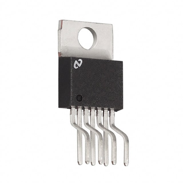
ICGOO电子元器件商城为您提供LM2599T-ADJ/NOPB由Texas Instruments设计生产,在icgoo商城现货销售,并且可以通过原厂、代理商等渠道进行代购。 LM2599T-ADJ/NOPB价格参考¥16.89-¥31.37。Texas InstrumentsLM2599T-ADJ/NOPB封装/规格:PMIC - 稳压器 - DC DC 开关稳压器, 可调式 降压 开关稳压器 IC 正 1.23V 1 输出 3A TO-220-7(成形引线)。您可以下载LM2599T-ADJ/NOPB参考资料、Datasheet数据手册功能说明书,资料中有LM2599T-ADJ/NOPB 详细功能的应用电路图电压和使用方法及教程。
| 参数 | 数值 |
| 产品目录 | 集成电路 (IC)半导体 |
| 描述 | IC REG BUCK ADJ 3A TO220-7稳压器—开关式稳压器 Pwr Cnvtr 150KHz 3A SD VTG Reg |
| 产品分类 | |
| 品牌 | Texas Instruments |
| 产品手册 | |
| 产品图片 |
|
| rohs | 符合RoHS无铅 / 符合限制有害物质指令(RoHS)规范要求 |
| 产品系列 | 电源管理 IC,稳压器—开关式稳压器,Texas Instruments LM2599T-ADJ/NOPBSIMPLE SWITCHER® |
| 数据手册 | |
| 产品型号 | LM2599T-ADJ/NOPB |
| PWM类型 | - |
| 产品培训模块 | http://www.digikey.cn/PTM/IndividualPTM.page?site=cn&lang=zhs&ptm=30128 |
| 产品种类 | 稳压器—开关式稳压器 |
| 供应商器件封装 | TO-220-7 |
| 其它名称 | *LM2599T-ADJ/NOPB |
| 制造商产品页 | http://www.ti.com/general/docs/suppproductinfo.tsp?distId=10&orderablePartNumber=LM2599T-ADJ/NOPB |
| 包装 | 管件 |
| 同步整流器 | 无 |
| 商标 | Texas Instruments |
| 商标名 | SIMPLE SWITCHER |
| 安装类型 | 通孔 |
| 安装风格 | Through Hole |
| 封装 | Tube |
| 封装/外壳 | TO-220-7 成形引线 |
| 封装/箱体 | TO-220 |
| 工作温度 | -40°C ~ 125°C |
| 工厂包装数量 | 45 |
| 开关频率 | 173 kHz |
| 最大工作温度 | + 125 C |
| 最大输入电压 | 40 V |
| 最小工作温度 | - 40 C |
| 最小输入电压 | 4.5 V |
| 标准包装 | 45 |
| 电压-输入 | 4.5 V ~ 40 V |
| 电压-输出 | 1.23 V ~ 37 V |
| 电流-输出 | 3A |
| 类型 | Step Down |
| 系列 | LM2599 |
| 设计资源 | http://www.digikey.com/product-highlights/cn/zh/texas-instruments-webench-design-center/3176 |
| 输出数 | 1 |
| 输出电压 | 1.2 V to 37 V |
| 输出电流 | 3 A |
| 输出端数量 | 1 Output |
| 输出类型 | 可调式 |
| 配用 | /product-detail/zh/551011367-021/551011367-021-ND/570332 |
| 频率-开关 | 150kHz |


- 商务部:美国ITC正式对集成电路等产品启动337调查
- 曝三星4nm工艺存在良率问题 高通将骁龙8 Gen1或转产台积电
- 太阳诱电将投资9.5亿元在常州建新厂生产MLCC 预计2023年完工
- 英特尔发布欧洲新工厂建设计划 深化IDM 2.0 战略
- 台积电先进制程称霸业界 有大客户加持明年业绩稳了
- 达到5530亿美元!SIA预计今年全球半导体销售额将创下新高
- 英特尔拟将自动驾驶子公司Mobileye上市 估值或超500亿美元
- 三星加码芯片和SET,合并消费电子和移动部门,撤换高东真等 CEO
- 三星电子宣布重大人事变动 还合并消费电子和移动部门
- 海关总署:前11个月进口集成电路产品价值2.52万亿元 增长14.8%


PDF Datasheet 数据手册内容提取
Product Sample & Technical Tools & Support & Folder Buy Documents Software Community LM2599 SNVS123D–APRIL1998–REVISEDMAY2016 LM2599 SIMPLE SWITCHER® Power Converter 150-kHz 3-A Step-Down Voltage Regulator, With Features 1 Features 3 Description • 3.3-V,5-V,12-V,andAdjustableOutputVersions The LM2599 series of regulators are monolithic 1 integrated circuits that provide all the active functions • AdjustableVersionOutputVoltageRange:1.2V for a step-down (buck) switching regulator, capable of to37V±4%MaximumOverLineandLoad driving a 3-A load with excellent line and load Conditions regulation.Thesedevicesareavailableinfixedoutput • 3-AOutputCurrent voltages of 3.3 V, 5 V, 12 V, and an adjustable output version. • Availablein7-PinTO-220andTO-263(Surface- Mount)Package The LM2598 is a member of the LM259x family, with • InputVoltageRangeUpto40V additional supervisory and performance features added. • 150-kHzFixed-FrequencyInternalOscillator • ShutdownandSoft-Start Requiring a minimum number of external components, these regulators are simple to use and • Out-of-RegulationErrorFlag include internal frequency compensation, improved • ErrorOutputDelay lineandloadspecifications,fixed-frequencyoscillator, • LowPowerStandbyMode,I ,Typically80μA Shutdown and Soft-start, error flag delay, and error Q flagoutput. • HighEfficiency • UsesReadilyAvailableStandardInductors DeviceInformation(1) • ThermalShutdownandCurrent-LimitProtection PARTNUMBER PACKAGE BODYSIZE(NOM) TO-220(7) 14.986mm×10.16mm 2 Applications LM2599 TO-263(7) 10.10mm×8.89mm • SimpleHigh-EfficiencyStep-Down(Buck) (1) For all available packages, see the orderable addendum at Regulator theendofthedatasheet. • EfficientPreregulatorforLinearRegulators • On-CardSwitchingRegulators • PositivetoNegativeConverter TypicalApplication (fixedoutputvoltageversions) 1 An IMPORTANT NOTICE at the end of this data sheet addresses availability, warranty, changes, use in safety-critical applications, intellectualpropertymattersandotherimportantdisclaimers.PRODUCTIONDATA.
LM2599 SNVS123D–APRIL1998–REVISEDMAY2016 www.ti.com Table of Contents 1 Features.................................................................. 1 8.1 Overview.................................................................10 2 Applications........................................................... 1 8.2 FunctionalBlockDiagram.......................................10 3 Description............................................................. 1 8.3 FeatureDescription.................................................10 8.4 DeviceFunctionalModes........................................15 4 RevisionHistory..................................................... 2 9 ApplicationandImplementation........................ 16 5 Description(continued)......................................... 3 9.1 ApplicationInformation............................................16 6 PinConfigurationandFunctions......................... 3 9.2 TypicalApplications................................................25 7 Specifications......................................................... 4 10 PowerSupplyRecommendations..................... 34 7.1 AbsoluteMaximumRatings .....................................4 11 Layout................................................................... 34 7.2 ESDRatings..............................................................4 11.1 LayoutGuidelines.................................................34 7.3 RecommendedOperatingConditions.......................4 11.2 LayoutExamples...................................................34 7.4 ThermalInformation..................................................4 11.3 ThermalConsiderations........................................35 7.5 ElectricalCharacteristics–3.3-VVersion.................5 12 DeviceandDocumentationSupport................. 38 7.6 ElectricalCharacteristics–5-VVersion....................5 7.7 ElectricalCharacteristics–12-VVersion..................5 12.1 CommunityResources..........................................38 7.8 ElectricalCharacteristics–AdjustableVoltage 12.2 Trademarks...........................................................38 Version....................................................................... 5 12.3 ElectrostaticDischargeCaution............................38 7.9 ElectricalCharacteristics–AllOutputVoltage 12.4 Glossary................................................................38 Versions.....................................................................6 13 Mechanical,Packaging,andOrderable 7.10 TypicalCharacteristics............................................7 Information........................................................... 38 8 DetailedDescription............................................ 10 4 Revision History NOTE:Pagenumbersforpreviousrevisionsmaydifferfrompagenumbersinthecurrentversion. ChangesfromRevisionC(April2013)toRevisionD Page • AddedESDRatingstable,FeatureDescriptionsection,DeviceFunctionalModes,ApplicationandImplementation section,PowerSupplyRecommendationssection,Layoutsection,DeviceandDocumentationSupportsection,and Mechanical,Packaging,andOrderableInformationsection.................................................................................................. 1 • RemovedallreferencestodesignsoftwareSwitchersMadeSimple ................................................................................... 1 ChangesfromRevisionB(April2013)toRevisionC Page • ChangedlayoutofNationalSemiconductorDataSheettoTIformat.................................................................................. 35 2 SubmitDocumentationFeedback Copyright©1998–2016,TexasInstrumentsIncorporated ProductFolderLinks:LM2599
LM2599 www.ti.com SNVS123D–APRIL1998–REVISEDMAY2016 5 Description (continued) The LM2599 series operates at a switching frequency of 150 kHz, thus allowing smaller sized filter components than what would be needed with lower frequency switching regulators. Available in a standard 7-pin TO-220 packagewithseveraldifferentleadbendoptions,anda7-pinTO-263surface-mountpackage. A standard series of inductors (both through-hole and surface-mount types) are available from several different manufacturers optimized for use with the LM2599 series. This feature greatly simplifies the design of switch- modepowersupplies. Other features include a ±4% tolerance on output voltage under all conditions of input voltage and output load conditions, and ±15% on the oscillator frequency. External shutdown is included, featuring typically 80-μA standby current. Self-protection features include a two stage current limit for the output switch and an overtemperatureshutdownforcompleteprotectionunderfaultconditions. 6 Pin Configuration and Functions NDZPackage 7-PinTO-220 KTWPackage TopView 7-PinTO-263 TopView PinFunctions(1) PIN I/O DESCRIPTION NO. NAME ThisisthepositiveinputsupplyfortheICswitchingregulator.Asuitableinputbypass 1 +V I capacitormustbepresentatthispintominimizevoltagetransientsandtosupplythe IN switchingcurrentsneededbytheregulator. Internalswitch.Thevoltageatthispinswitchesbetweenapproximately(+V −V )and IN SAT 2 Output O approximately−0.5V,withadutycycleofV /V .Tominimizecouplingtosensitive OUT IN circuitry,thePCBcopperareaconnectedtothispinmustbekepttoaminimum. Open-collectoroutputthatprovidesalowsignal(flagtransistorON)whentheregulated outputvoltagedropsmorethan5%fromthenominaloutputvoltage.Onstartup,ErrorFlag 3 ErrorFlag O islowuntilV reaches95%ofthenominaloutputvoltageandadelaytimedeterminedby OUT theDelaypincapacitor.Thissignalcanbeusedasaresettoamicroprocessoronpower- up. 4 Ground — Circuitground. Atpower-up,thispincanbeusedtoprovideatimedelaybetweenthetimetheregulated 5 Delay O outputvoltagereaches95%ofthenominaloutputvoltage,andthetimetheerrorflagoutput goeshigh. 6 Feedback I Sensestheregulatedoutputvoltagetocompletethefeedbackloop. Thisdualfunctionpinprovidesthefollowingfeatures:(a)Allowstheswitchingregulator circuittobeshutdownusinglogiclevelsignalsthusdroppingthetotalinputsupplycurrent 7 Shutdown/Soft-start I toapproximately80μA.(b)Addingacapacitortothispinprovidesasoft-startfeaturewhich minimizesstart-upcurrentandprovidesacontrolledrampupoftheoutputvoltage. (1) Ifanyoftheabovethreefeatures(Shutdown/Soft-start,ErrorFlag,orDelay)arenotused,therespectivepinsmustbeleftopen. Copyright©1998–2016,TexasInstrumentsIncorporated SubmitDocumentationFeedback 3 ProductFolderLinks:LM2599
LM2599 SNVS123D–APRIL1998–REVISEDMAY2016 www.ti.com 7 Specifications 7.1 Absolute Maximum Ratings (1)(2) MIN MAX UNIT Maximumsupplyvoltage,V 45 V IN SD/SSpininputvoltage(3) 6 V Delaypinvoltage(3) 1.5 V Flagpinvoltage –0.3 45 V Feedbackpinvoltage –0.3 25 V Outputvoltagetoground(steady-state) –1 V Powerdissipation Internallylimited Vaporphase(60s) 215 KTWpackage Leadtemperature Infrared(10s) 245 °C NDZpackage(soldering,10s) 260 Maximumjunctiontemperature 150 °C Storagetemperature,T −65 150 °C stg (1) StressesbeyondthoselistedunderAbsoluteMaximumRatingsmaycausepermanentdamagetothedevice.Thesearestressratings only,whichdonotimplyfunctionaloperationofthedeviceattheseoranyotherconditionsbeyondthoseindicatedunderRecommended OperatingConditions.Exposuretoabsolute-maximum-ratedconditionsforextendedperiodsmayaffectdevicereliability. (2) IfMilitary/Aerospacespecifieddevicesarerequired,pleasecontacttheTexasInstrumentsSalesOffice/Distributorsforavailabilityand specifications. (3) Voltageinternallyclamped.Ifclampvoltageisexceeded,limitcurrenttoamaximumof1mA. 7.2 ESD Ratings VALUE UNIT V Electrostatic Human-bodymodel(HBM),perANSI/ESDA/JEDECJS-001(1) ±2000 V (ESD) discharge (1) JEDECdocumentJEP155statesthat500-VHBMallowssafemanufacturingwithastandardESDcontrolprocess. 7.3 Recommended Operating Conditions MIN MAX UNIT Supplyvoltage 4.5 40 V Temperature –40 125 °C 7.4 Thermal Information LM2599 THERMALMETRIC(1) KTW(TO-263) NDZ(TO-220) UNIT 7PINS 7PINS See(4) — 50 See(5) 50 — RθJA Junction-to-ambientthermalresistance(2)(3) See(6) 30 — °C/W See(7) 20 — RθJC(top) Junction-to-case(top)thermalresistance 2 2 °C/W (1) Formoreinformationabouttraditionalandnewthermalmetrics,seetheSemiconductorandICPackageThermalMetricsapplication report,SPRA953. (2) ThepackagethermalimpedanceiscalculatedinaccordancetoJESD51-7. (3) Thermalresistancesweresimulatedona4-layer,JEDECboard. (4) Junctiontoambientthermalresistance(noexternalheatsink)forthepackagemountedTO-220packagemountedvertically,withthe leadssolderedtoaPCBwith1-ozcopperareaofapproximately1in2. (5) JunctiontoambientthermalresistancewiththeTO-263packagetabsolderedtoasingle-sidedPCBwith0.5in2of1-ozcopperarea. (6) JunctiontoambientthermalresistancewiththeTO-263packagetabsolderedtoasingle-sidedPCBwith2.5in2of1-ozcopperarea. (7) JunctiontoambientthermalresistancewiththeTO-263packagetabsolderedtoadouble-sidedPCBwith3in2of1-ozcopperareaon theLM2599Ssideoftheboard,andapproximately16in2ofcopperontheothersideofthePCB. 4 SubmitDocumentationFeedback Copyright©1998–2016,TexasInstrumentsIncorporated ProductFolderLinks:LM2599
LM2599 www.ti.com SNVS123D–APRIL1998–REVISEDMAY2016 7.5 Electrical Characteristics – 3.3-V Version SpecificationsareforT =25°C(unlessotherwisenoted). J PARAMETER TESTCONDITIONS MIN(1) TYP(2) MAX (1) UNIT SYSTEMPARAMETERS(3)(seeFigure43fortestcircuit) V Outputvoltage 4.75V≤VIN≤40V, TJ=25°C 3.168 3.3 3.432 V OUT 0.2A≤ILOAD≤3A –40°C≤TJ≤125°C 3.135 3.465 η Efficiency V =12V,I =3A 73% IN LOAD (1) Allroomtemperaturelimitsare100%productiontested.Alllimitsattemperatureextremesarespecifiedviacorrelationusingstandard StatisticalQualityControl(SQC)methods.AlllimitsareusedtocalculateAverageOutgoingQualityLevel(AOQL). (2) Typicalnumbersareat25°Candrepresentthemostlikelynorm. (3) Externalcomponentssuchasthecatchdiode,inductor,inputandoutputcapacitorscanaffectswitchingregulatorsystemperformance. WhentheLM2599isusedasshowninFigure43,systemperformanceisshowninthetestconditionscolumn. 7.6 Electrical Characteristics – 5-V Version SpecificationsareforT =25°C(unlessotherwisenoted). J PARAMETER TESTCONDITIONS MIN(1) TYP(2) MAX(1) UNIT SYSTEMPARAMETERS(3)(seeFigure43fortestcircuit) V Outputvoltage 7V≤VIN≤40V, TJ=25°C 4.8 5 5.2 V OUT 0.2A≤ILOAD≤3A –40°C≤TJ≤125°C 4.75 5.25 η Efficiency V =12V,I =3A 80% IN LOAD (1) Allroomtemperaturelimitsare100%productiontested.Alllimitsattemperatureextremesarespecifiedviacorrelationusingstandard StatisticalQualityControl(SQC)methods.AlllimitsareusedtocalculateAverageOutgoingQualityLevel(AOQL). (2) Typicalnumbersareat25°Candrepresentthemostlikelynorm. (3) Externalcomponentssuchasthecatchdiode,inductor,inputandoutputcapacitorscanaffectswitchingregulatorsystemperformance. WhentheLM2599isusedasshowninFigure43,systemperformanceisshowninthetestconditionscolumn. 7.7 Electrical Characteristics – 12-V Version SpecificationsareforT =25°C(unlessotherwisenoted). J PARAMETER TESTCONDITIONS MIN(1) TYP(2) MAX(1) UNIT SYSTEMPARAMETERS(3)(seeFigure43fortestcircuit) V Outputvoltage 15V≤VIN≤40V, TJ=25°C 11.52 12 12.48 V OUT 0.2A≤ILOAD≤3A –40°C≤TJ≤125°C 11.4 12.6 η Efficiency V =25V,I =3A 90% IN LOAD (1) Allroomtemperaturelimitsare100%productiontested.Alllimitsattemperatureextremesarespecifiedviacorrelationusingstandard StatisticalQualityControl(SQC)methods.AlllimitsareusedtocalculateAverageOutgoingQualityLevel(AOQL). (2) Typicalnumbersareat25°Candrepresentthemostlikelynorm. (3) Externalcomponentssuchasthecatchdiode,inductor,inputandoutputcapacitorscanaffectswitchingregulatorsystemperformance. WhentheLM2599isusedasshowninFigure43,systemperformanceisshowninthetestconditionscolumn. 7.8 Electrical Characteristics – Adjustable Voltage Version SpecificationsareforT =25°C(unlessotherwisenoted). J PARAMETER TESTCONDITIONS MIN(1) TYP(2) MAX(1) UNIT SYSTEMPARAMETERS(3)(seeFigure43fortestcircuit) 4.5V≤V ≤40V,0.2A≤I ≤3A 1.23 IN LOAD VFB Feedbackvoltage VOUTprogrammedfor3V, TJ=25°C 1.193 1.267 V circuitofFigure43 –40°C≤T ≤125°C 1.18 1.28 J η Efficiency V =12V,V =3V,I =3A 73% IN OUT LOAD (1) Allroomtemperaturelimitsare100%productiontested.Alllimitsattemperatureextremesarespecifiedviacorrelationusingstandard StatisticalQualityControl(SQC)methods.AlllimitsareusedtocalculateAverageOutgoingQualityLevel(AOQL). (2) Typicalnumbersareat25°Candrepresentthemostlikelynorm. (3) Externalcomponentssuchasthecatchdiode,inductor,inputandoutputcapacitorscanaffectswitchingregulatorsystemperformance. WhentheLM2599isusedasshowninFigure43,systemperformanceisshowninthetestconditionscolumn. Copyright©1998–2016,TexasInstrumentsIncorporated SubmitDocumentationFeedback 5 ProductFolderLinks:LM2599
LM2599 SNVS123D–APRIL1998–REVISEDMAY2016 www.ti.com 7.9 Electrical Characteristics – All Output Voltage Versions SpecificationsareforT =25°C,I =500mA,V =12Vforthe3.3-V,5-V,andAdjustableversion,andV =24Vforthe J LOAD IN IN 12-Vversion(unlessotherwisenoted). PARAMETER TESTCONDITIONS MIN(1) TYP(2) MAX(1) UNIT DEVICEPARAMETERS Adjustablevoltage T =25°C 10 50 J I Feedbackbiascurrent versiononly,V =1.3 nA b FB V –40°C≤TJ≤125°C 100 T =25°C 127 150 173 f Oscillatorfrequency(3) J kHz O –40°C≤T ≤125°C 110 173 J T =25°C 1.16 1.4 V Saturationvoltage I =3A(4)(5) J V SAT OUT –40°C≤T ≤125°C 1.5 J Maxdutycycle(ON)(5) 100% DC Mindutycycle(OFF)(6) 0% TJ=25°C 3.6 4.5 6.9 I Currentlimit Peakcurrent(4) (5) A CL –40°C≤TJ≤125°C 3.4 7.5 Output=0V,V =40V(4) (6) 50 μA IN I Outputleakagecurrent L Output=−1V 2 30 mA I Operatingquiescentcurrent SD/SSpinopen(6) 5 10 mA Q I Currentstandbyquiescent SD/SSpin=0V,VIN= TJ=25°C 80 200 μA STBY 40V –40°C≤T ≤125°C 250 μA J SHUTDOWN/SOFT-STARTCONTROL–SeeFigure43 1.3 V Shutdownthresholdvoltage Low(Shutdownmode),–40°C≤T ≤125°C 0.6 V SD J High(Soft-startmode),–40°C≤T ≤125°C 2 J V =20%ofnominaloutputvoltage 2 OUT V Soft-startvoltage V SS V =100%ofnominaloutputvoltage 3 OUT I Shutdowncurrent V =0.5V 5 10 μA SD SHUTDOWN I Soft-startcurrent V =2.5V 1.6 5 μA SS Soft-start FLAG/DELAYCONTROL–SeeFigure43 Regulatordropoutdetector Low(flagON) 92% 96% 98% thresholdvoltage I =3mA 0.3 V SINK VF Voltageflagoutputsaturation T =25°C 0.7 SAT J V =0.5V V DELAY –40°C≤T ≤125°C 1 J IF Flagoutputleakagecurrent V =40V 0.3 μA L FLAG 1.25 V Voltagedelaypinthreshold Low(flagON) 1.21 V High(flagOFF)andV regulated 1.29 OUT Delaypinsourcecurrent V =0.5V 3 6 μA DELAY T =25°C 55 350 J Delaypinsaturation Low(flagON) mV –40°C≤T ≤125°C 400 J (1) Allroomtemperaturelimitsare100%productiontested.Alllimitsattemperatureextremesarespecifiedviacorrelationusingstandard StatisticalQualityControl(SQC)methods.AlllimitsareusedtocalculateAverageOutgoingQualityLevel(AOQL). (2) Typicalnumbersareat25°Candrepresentthemostlikelynorm. (3) Theswitchingfrequencyisreducedwhenthesecondstagecurrentlimitisactivated.Theamountofreductionisdeterminedbythe severityofcurrentoverload. (4) Nodiode,inductororcapacitorconnectedtooutputpin. (5) Feedbackpinremovedfromoutputandconnectedto0VtoforcetheoutputtransistorswitchON. (6) Feedbackpinremovedfromoutputandconnectedto12Vforthe3.3-V,5-V,andtheadjustableversions,and15Vforthe12-V version,toforcetheoutputtransistorswitchOFF. 6 SubmitDocumentationFeedback Copyright©1998–2016,TexasInstrumentsIncorporated ProductFolderLinks:LM2599
LM2599 www.ti.com SNVS123D–APRIL1998–REVISEDMAY2016 7.10 Typical Characteristics SeeFigure43fortestcircuit Figure1.NormalizedOutputVoltage Figure2.LineRegulation Figure3.Efficiency Figure4.SwitchSaturationVoltage Figure5.SwitchCurrentLimit Figure6.DropoutVoltage Copyright©1998–2016,TexasInstrumentsIncorporated SubmitDocumentationFeedback 7 ProductFolderLinks:LM2599
LM2599 SNVS123D–APRIL1998–REVISEDMAY2016 www.ti.com Typical Characteristics (continued) SeeFigure43fortestcircuit Figure7.OperatingQuiescentCurrent Figure8.ShutdownQuiescentCurrent Figure9.MinimumOperatingSupplyVoltage Figure10.FeedbackPinBiasCurrent Figure11.FlagSaturationVoltage Figure12.SwitchingFrequency 8 SubmitDocumentationFeedback Copyright©1998–2016,TexasInstrumentsIncorporated ProductFolderLinks:LM2599
LM2599 www.ti.com SNVS123D–APRIL1998–REVISEDMAY2016 Typical Characteristics (continued) SeeFigure43fortestcircuit Figure13.Soft-Start Figure14.Shutdown/Soft-StartCurrent Figure15.DaisyPinCurrent Figure16.Soft-StartResponse Figure17.Shutdown/Soft-StartThresholdVoltage Copyright©1998–2016,TexasInstrumentsIncorporated SubmitDocumentationFeedback 9 ProductFolderLinks:LM2599
LM2599 SNVS123D–APRIL1998–REVISEDMAY2016 www.ti.com 8 Detailed Description 8.1 Overview The LM2599 SIMPLE SWITCHER® regulator is an easy-to-use, nonsynchronous, step-down DC-DC converter with a wide input voltage range up to 40 V. The regulator is capable of delivering up to 3-A DC load current with excellent line and load regulation. These devices are available in fixed output voltages of 3.3 V, 5 V, 12 V, and an adjustable output version. The family requires few external components, and the pin arrangement was designedforsimple,optimumPCBlayout. 8.2 Functional Block Diagram 8.3 Feature Description 8.3.1 Shutdown/Soft-Start The circuit shown in Figure 20 is a standard buck regulator with 20-V , 12-V , 1-A load using a 0.068-μF soft- IN OUT start capacitor. Figure 18 and Figure 19 show the effects of soft-start on the output voltage, the input current, with, and without a soft-start capacitor. The reduced input current required at startup is very evident when comparing the two photos. The soft-start feature reduces the start-up current from 2.6 A down to 650 mA, and delaysandslowsdowntheoutputvoltagerisetime. 10 SubmitDocumentationFeedback Copyright©1998–2016,TexasInstrumentsIncorporated ProductFolderLinks:LM2599
LM2599 www.ti.com SNVS123D–APRIL1998–REVISEDMAY2016 Feature Description (continued) Figure18.OutputVoltageandInputCurrent Figure19.OutputVoltageandInputCurrent atStart-UpWithSoft-Start atStart-UpWithoutSoft-Start This reduction in start-up current is useful in situations where the input power source is limited in the amount of current it can deliver. In some applications soft-start can be used to replace undervoltage lockout or delayed start-upfunctions. If a very slow output voltage ramp is desired, the soft-start capacitor can be made much larger. Many seconds or evenminutesarepossible. Ifonlytheshutdownfeatureisneeded,thesoft-startcapacitorcanbeeliminated. Figure20. TypicalCircuitUsing Shutdown/Soft-StartandErrorFlagFeatures Copyright©1998–2016,TexasInstrumentsIncorporated SubmitDocumentationFeedback 11 ProductFolderLinks:LM2599
LM2599 SNVS123D–APRIL1998–REVISEDMAY2016 www.ti.com Feature Description (continued) Figure21. Inverting −5-VRegulatorWithShutdownandSoft-Start 8.3.2 InvertingRegulator ThecircuitinFigure21convertsapositiveinputvoltagetoanegativeoutputvoltagewithacommonground.The circuit operates by bootstrapping the ground pin of the regulator to the negative output voltage, then grounding thefeedbackpin,theregulatorsensestheinvertedoutputvoltageandregulatesit. This example uses the LM2599-5 to generate a −5-V output, but other output voltages are possible by selecting other output voltage versions, including the adjustable version. Because this regulator topology can produce an output voltage that is either greater than or less than the input voltage, the maximum output current greatly depends on both the input and output voltage. The curve shown in Figure 22 provides a guide as to the amount ofoutputloadcurrentpossibleforthedifferentinputandoutputvoltageconditions. The maximum voltage appearing across the regulator is the absolute sum of the input and output voltage, and this must be limited to a maximum of 40 V. In this example, when converting 20 V to −5 V, the regulator would see25Vbetweentheinputpinandgroundpin.TheLM2599hasamaximuminputvoltageratingof40V. Figure22. MaximumLoadCurrentforInvertingRegulatorCircuit 12 SubmitDocumentationFeedback Copyright©1998–2016,TexasInstrumentsIncorporated ProductFolderLinks:LM2599
LM2599 www.ti.com SNVS123D–APRIL1998–REVISEDMAY2016 Feature Description (continued) An additional diode is required in this regulator configuration. Diode D1 is used to isolate input voltage ripple or noise from coupling through the C capacitor to the output, under light or no load conditions. Also, this diode IN isolationchangesthetopologytocloselyresembleabuckconfiguration,thusprovidinggoodclosed-loopstability. TI recommends a Schottky diode for low input voltages, (because of its lower voltage drop) but for higher input voltages,aIN5400diodecouldbeused. Because of differences in the operation of the inverting regulator, the standard design procedure is not used to select the inductor value. In the majority of designs, a 33-μH, 3.5-A inductor is the best choice. Capacitor selection can also be narrowed down to just a few values. Using the values shown in Figure 21 provides good resultsinthemajorityofinvertingdesigns. This type of inverting regulator can require relatively large amounts of input current when starting up, even with light loads. Input currents as high as the LM2599 current limit (approximately 4.5 A) are needed for 2 ms or more, until the output reaches its nominal output voltage. The actual time depends on the output voltage and the size of the output capacitor. Input power sources that are current limited or sources that can not deliver these currents without getting loaded down, may not work correctly. Because of the relatively high startup currents requiredbytheinvertingtopology,thesoft-startfeatureshowninFigure21 isrecommended. Also shown in Figure 21 are several shutdown methods for the inverting configuration. With the inverting configuration, some level shifting is required, because the ground pin of the regulator is no longer at ground, but is now at the negative output voltage. The shutdown methods shown accept ground referenced shutdown signals. 8.3.3 UndervoltageLockout Some applications require the regulator to remain off until the input voltage reaches a predetermined voltage. Figure 23 contains a undervoltage lockout circuit for a buck configuration, while Figure 24 and Figure 25 are for the inverting types (only the circuitry pertaining to the undervoltage lockout is shown). Figure 23 uses a Zener diode to establish the threshold voltage when the switcher begins operating. When the input voltage is less than the Zener voltage, resistors R1 and R2 hold the shutdown/soft-start pin low, keeping the regulator in the shutdown mode. As the input voltage exceeds the Zener voltage, the Zener conducts, pulling the shutdown/soft- start pin high, allowing the regulator to begin switching. The threshold voltage for the undervoltage lockout featureisapproximately1.5VgreaterthantheZenervoltage. Figure23. UndervoltageLockoutforaBuckRegulator Figure 24 and Figure 25 apply the same feature to an inverting circuit. Figure 24 features a constant threshold voltage for turn on and turn off (Zener voltage plus approximately one volt). If hysteresis is needed, the circuit in Figure 25 has a turn ON voltage which is different than the turn OFF voltage. The amount of hysteresis is approximately equal to the value of the output voltage. Because the SD/SS pin has an internal 7-V Zener clamp, R2isneededtolimitthecurrentintothispintoapproximately1mAwhenQ1ison. Copyright©1998–2016,TexasInstrumentsIncorporated SubmitDocumentationFeedback 13 ProductFolderLinks:LM2599
LM2599 SNVS123D–APRIL1998–REVISEDMAY2016 www.ti.com Feature Description (continued) Figure24. UndervoltageLockoutWithoutHysteresisforanInvertingRegulator Figure25. UndervoltageLockoutWithHysteresisforanInvertingRegulator 8.3.4 NegativeVoltageChargePump Occasionally a low-current negative voltage is needed for biasing parts of a circuit. A simple method of generating a negative voltage using a charge pump technique and the switching waveform present at the OUT pin, is shown in Figure 26. This unregulated negative voltage is approximately equal to the positive input voltage (minus a few volts), and can supply up to a 600 mA of output current. There is a requirement however, that there be a minimum load of 1.2 A on the regulated positive output for the charge pump to work correctly. Also, resistor R1 is required to limit the charging current of C1 to some value less than the LM2599 current limit (typically 4.5A). This method of generating a negative output voltage without an additional inductor can be used with other membersoftheSIMPLESWITCHERFamily,usingeitherthebuckorboosttopology. Figure26. ChargePumpforGeneratingaLow-Current,Negative-OutputVoltage 14 SubmitDocumentationFeedback Copyright©1998–2016,TexasInstrumentsIncorporated ProductFolderLinks:LM2599
LM2599 www.ti.com SNVS123D–APRIL1998–REVISEDMAY2016 8.4 Device Functional Modes 8.4.1 DiscontinuousModeOperation The selection guide chooses inductor values suitable for continuous mode operation, but for low current applications or high input voltages, a discontinuous mode design may be a better choice. The design would use an inductor that would be physically smaller, and would need only one half to one third the inductance value neededforacontinuousmodedesign.Thepeakswitchandinductorcurrentsishigherinadiscontinuousdesign, but at these low load currents (1 A and below), the maximum switch current is still less than the switch current limit. Discontinuous operation can have voltage waveforms that are considerably different than a continuous design. The output pin (switch) waveform can have some damped sinusoidal ringing present (see Figure 44). This ringing is normal for discontinuous operation, and is not caused by feedback loop instabilities. In discontinuous operation, there is a period of time where neither the switch nor the diode are conducting, and the inductor current has dropped to zero. During this time, a small amount of energy can circulate between the inductor and the switch and diode parasitic capacitance causing this characteristic ringing. Normally this ringing is not a problem, unless the amplitude becomes great enough to exceed the input voltage, and even then, there is very littleenergypresenttocausedamage. Different inductor types or core materials produce different amounts of this characteristic ringing. Ferrite core inductorshaveverylittlecorelossandthereforeproducethemostringing.Thehighercorelossofpowderediron inductorsproducelessringing.Ifdesired,aseriesRCcouldbeplacedinparallelwiththeinductortodampenthe ringing. Figure27. PostRippleFilterWaveform Copyright©1998–2016,TexasInstrumentsIncorporated SubmitDocumentationFeedback 15 ProductFolderLinks:LM2599
LM2599 SNVS123D–APRIL1998–REVISEDMAY2016 www.ti.com 9 Application and Implementation NOTE Information in the following applications sections is not part of the TI component specification, and TI does not warrant its accuracy or completeness. TI’s customers are responsible for determining suitability of components for their purposes. Customers should validateandtesttheirdesignimplementationtoconfirmsystemfunctionality. 9.1 Application Information 9.1.1 Soft-StartCapacitor(C ) SS The capacitor on this pin provides the regulator with a soft-start feature (slow start-up). When the DC input voltage is first applied to the regulator, or when the Shutdown/Soft-start pin is allowed to go high, a constant current (approximately 5 μA begins charging this capacitor). As the capacitor voltage rises, the regulator goes throughfouroperatingregions(seethebottomcurveinFigure28): 1. Regulator in Shutdown: When the SD/SS pin voltage is between 0 V and 1.3 V, the regulator is in shutdown, theoutputvoltageiszero,andtheICquiescentcurrentisapproximately85 μA. 2. Regulator ON, but the output voltage is zero: With the SD/SS pin voltage between approximately 1.3 V and 1.8 V, the internal regulator circuitry is operating, the quiescent current rises to approximately 5 mA, but the output voltage is still zero. Also, as the 1.3-V threshold is exceeded, the soft-start capacitor charging current decreasesfrom5μAdowntoapproximately1.6 μA.Thisdecreasestheslopeofcapacitorvoltageramp. 3. Soft-start Region: When the SD/SS pin voltage is between 1.8 V and 2.8 V (at 25°C), the regulator is in a soft-startcondition.Theswitch(Pin2)dutycycleinitiallystartsoutverylow,withnarrowpulsesandgradually get wider as the capacitor SD/SS pin ramps up towards 2.8 V. As the duty cycle increases, the output voltage also increases at a controlled ramp up (see the center curve in Figure 28) The input supply current requirement also starts out at a low level for the narrow pulses and ramp up in a controlled manner. This is a very useful feature in some switcher topologies that require large start-up currents (such as the inverting configuration)whichcanloaddowntheinputpowersupply. NOTE The lower curve shown in Figure 28 shows the soft-start region from 0% to 100%. This is not the duty cycle percentage, but the output voltage percentage. Also, the soft-start voltage range has a negative temperature coefficient associated with it. See the soft-start sectioninElectricalCharacteristics– AllOutputVoltageVersions. 4. Normal operation: Above 2.8 V, the circuit operates as a standard Pulse Width Modulated switching regulator. The capacitor continues to charge up until it reaches the internal clamp voltage of approximately 7 V.Ifthispinisdrivenfromavoltagesource,thecurrentmustbelimitedtoabout1mA. If the part is operated with an input voltage at or below the internal soft-start clamp voltage of approximately 7 V, the voltage on the SD/SS pin tracks the input voltage and can be disturbed by a step in the voltage. To maintain proper function under these conditions, TI strongly recommends clamping the SD/SS pin externally between the 3-V maximum soft-start threshold and the 4.5-V minimum input voltage. Figure 30 is an example of an external 3.7-V (approximately) clamp that prevents a line-step related glitch but does not interfere with the soft-start behaviorofthedevice. 16 SubmitDocumentationFeedback Copyright©1998–2016,TexasInstrumentsIncorporated ProductFolderLinks:LM2599
LM2599 www.ti.com SNVS123D–APRIL1998–REVISEDMAY2016 Application Information (continued) Figure28. Soft-Start,Delay,Error,Output Figure29. TimingDiagramfor5-VOutput Copyright©1998–2016,TexasInstrumentsIncorporated SubmitDocumentationFeedback 17 ProductFolderLinks:LM2599
LM2599 SNVS123D–APRIL1998–REVISEDMAY2016 www.ti.com Application Information (continued) VIN LM2599 5 Q1 SD/SS CSS Z1 3V Figure30. External3.7-VSoft-StartClamp 9.1.2 DelayCapacitor(C ) DELAY This capacitor provides delay for the error flag output (see Figure 28 and Figure 29). A capacitor on this pin provides a time delay between the time the regulated output voltage (when it is increasing in value) reaches 95% of the nominal output voltage, and the time the error flag output goes high. A 3-μA constant current from the delay pin charges the delay capacitor resulting in a voltage ramp. When this voltage reaches a threshold of approximately 1.3 V, the open-collector error flag output (or power OK) goes high. This signal can be used to indicatethattheregulatedoutputhasreachedthecorrectvoltageandhasstabilized. If, for any reason, the regulated output voltage drops by 5% or more, the error output flag (Pin 3) immediately goes low (internal transistor turns on). The delay capacitor provides very little delay if the regulated output is dropping out of regulation. The delay time for an output that is decreasing is approximately a 1000 times less than the delay for the rising output. For a 0.1-μF delay capacitor, the delay time would be approximately 50 ms whentheoutputisrisingandpassesthroughthe95%threshold,butthedelayfortheoutputdroppingwouldonly beapproximately50μs. 9.1.2.1 R PULLUP The error flag output (or power OK) is the collector of a NPN transistor, with the emitter internally grounded. To use the error flag, a pullup resistor to a positive voltage is needed. The error flag transistor is rated up to a maximumof45Vandcansinkapproximately3mA.Iftheerrorflagisnotused,itcanbeleftopen. 9.1.3 FeedforwardCapacitor(C )forAdjustableOutputVoltageVersionOnly FF A feedforward capacitor, C , is used when the output voltage is greater than 10 V or when C has a very low FF OUT ESR. This capacitor adds lead compensation to the feedback loop and increases the phase margin for better loopstability. If the output ripple is large (> 5% of the nominal output voltage), this ripple can be coupled to the feedback pin through the feedforward capacitor and cause the error comparator to trigger the error flag. In this situation, adding a resistor, R , in series with the feedforward capacitor, approximately 3 times R1, attenuates the ripple FF voltageatthefeedbackpin. 9.1.4 InputCapacitor(C ) IN A low-ESR aluminum or tantalum bypass capacitor is required between the input pin and ground pin. The capacitor must be placed near the regulator using short leads. This capacitor prevents large voltage transients fromappearingattheinput,andprovidestheinstantaneouscurrentneededeachtimetheswitchturnson. The important parameters for the Input capacitor are the voltage rating and the RMS current rating. Because of the relatively high RMS currents flowing in a input capacitor of the buck regulator, this capacitor must be chosen for its RMS current rating rather than its capacitance or voltage ratings, although the capacitance value and voltageratingaredirectlyrelatedtotheRMScurrentrating. 18 SubmitDocumentationFeedback Copyright©1998–2016,TexasInstrumentsIncorporated ProductFolderLinks:LM2599
LM2599 www.ti.com SNVS123D–APRIL1998–REVISEDMAY2016 Application Information (continued) The RMS current rating of a capacitor could be viewed as a power rating of the capacitor. The RMS current flowing through the capacitors internal ESR produces power which causes the internal temperature of the capacitor to rise. The RMS current rating of a capacitor is determined by the amount of current required to raise theinternaltemperatureapproximately10°Caboveanambienttemperatureof105°C.Theabilityofthecapacitor to dissipate this heat to the surrounding air determines the amount of current the capacitor can safely sustain. CapacitorsthatarephysicallylargeandhavealargesurfaceareatypicallyhasahigherRMScurrentratings.For a given capacitor value, a higher voltage electrolytic capacitor is physically larger than a lower voltage capacitor, andthusbeabletodissipatemoreheattothesurroundingair,andthereforehasahigherRMScurrentrating. Figure32.CapacitorESRvsCapacitorVoltageRating (TypicalLow-ESRElectrolyticCapacitor) Figure31.RMSCurrentRatingsforLow-ESRElectrolytic Capacitors(Typical) The consequences of operating an electrolytic capacitor above the RMS current rating is a shortened operating life.Thehighertemperaturespeedsuptheevaporationofthecapacitor'selectrolyte,resultingineventualfailure. SelectinganinputcapacitorrequiresconsultingthemanufacturersdatasheetformaximumallowableRMSripple current. For a maximum ambient temperature of 40°C, a general guideline would be to select a capacitor with a ripple current rating of approximately 50% of the DC load current. For ambient temperatures up to 70°C, a current rating of 75% of the DC load current would be a good choice for a conservative design. The capacitor voltage rating must be at least 1.25 times greater than the maximum input voltage, and often a much higher voltagecapacitorisneededtosatisfytheRMScurrentrequirements. Figure 31 shows the relationship between an electrolytic capacitor value, its voltage rating, and the RMS current it is rated for. These curves were obtained from the Nichicon PL series of low-ESR, high-reliability electrolytic capacitors designed for switching regulator applications. Other capacitor manufacturers offer similar types of capacitors,butalwayscheckthecapacitordatasheet. Standard electrolytic capacitors typically have much higher ESR numbers, lower RMS current ratings and typicallyhaveashorteroperatinglifetime. Because of their small size and excellent performance, surface-mount solid tantalum capacitors are often used for input bypassing, but several precautions must be observed. A small percentage of solid tantalum capacitors can short if the inrush current rating is exceeded. This can happen at turnon when the input voltage is suddenly applied, and of course, higher input voltages produce higher inrush currents. Several capacitor manufacturers do a 100% surge current testing on their products to minimize this potential problem. If high turnon currents are expected, it may be necessary to limit this current by adding either some resistance or inductance before the tantalum capacitor, or select a higher voltage capacitor. As with aluminum electrolytic capacitors, the RMS ripple currentratingmustbesizedtotheloadcurrent. Copyright©1998–2016,TexasInstrumentsIncorporated SubmitDocumentationFeedback 19 ProductFolderLinks:LM2599
LM2599 SNVS123D–APRIL1998–REVISEDMAY2016 www.ti.com Application Information (continued) 9.1.5 OutputCapacitor(C ) OUT Anoutputcapacitorisrequiredtofiltertheoutputandprovideregulatorloopstability.Lowimpedanceorlow-ESR Electrolytic or solid tantalum capacitors designed for switching regulator applications must be used. When selecting an output capacitor, the important capacitor parameters are; the 100-kHz Equivalent Series Resistance (ESR), the RMS ripple current rating, voltage rating, and capacitance value. For the output capacitor, the ESR valueisthemostimportantparameter. The output capacitor requires an ESR value that has an upper and lower limit. For low output ripple voltage, a low ESR value is needed. This value is determined by the maximum allowable output ripple voltage, typically 1% to 2% of the output voltage. But if the ESR of the selected capacitor' is extremely low, there is a possibility of an unstable feedback loop, resulting in an oscillation at the output. Using the capacitors listed in the tables, or similartypes,providesdesignsolutionsunderallconditions. If very low output ripple voltage (less than 15 mV) is required, see Output Voltage Ripple and Transients for a postripplefilter. An aluminum electrolytic capacitor's ESR value is related to the capacitance value and its voltage rating. In most cases, higher voltage electrolytic capacitors have lower ESR values (see Figure 32). Often, capacitors with much highervoltageratingsmaybeneededtoprovidethelowESRvaluesrequiredforlowoutputripplevoltage. The output capacitor for many different switcher designs often can be satisfied with only three or four different capacitor values and several different voltage ratings. See the quick design component selection tables in Table3andTable6fortypicalcapacitorvalues,voltageratings,andmanufacturercapacitortypes. Electrolytic capacitors are not recommended for temperatures below −25°C. The ESR rises dramatically at cold temperaturesandtypicallyrises3Xat −25°Candasmuchas10Xat −40°C(seeFigure33). Solid tantalum capacitors have a much better ESR specification for cold temperatures and are recommended for temperaturesbelow−25°C. 9.1.6 CatchDiode Buck regulators require a diode to provide a return path for the inductor current when the switch turns off. This mustbeafastdiodeandmustbeplacedclosetotheLM2599usingshortleadsandshortprintedcircuittraces. Because of their very fast switching speed and low forward voltage drop, Schottky diodes provide the best performance, especially in low output voltage applications (5 V and lower). Ultra-fast recovery, or high-efficiency rectifiers are also a good choice, but some types with an abrupt turnoff characteristic may cause instability or EMI problems. Ultra-fast recovery diodes typically have reverse recovery times of 50 ns or less. Rectifiers such astheIN5400seriesaremuchtooslowandmustnotbeused. Figure33. CapacitorESRChangevsTemperature 20 SubmitDocumentationFeedback Copyright©1998–2016,TexasInstrumentsIncorporated ProductFolderLinks:LM2599
LM2599 www.ti.com SNVS123D–APRIL1998–REVISEDMAY2016 Application Information (continued) 9.1.7 InductorSelection All switching regulators have two basic modes of operation; continuous and discontinuous. The difference betweenthetwotypesrelatestotheinductorcurrent,whetheritisflowingcontinuously,orifitdropstozerofora period of time in the normal switching cycle. Each mode has distinctively different operating characteristics, which can affect the regulators performance and requirements. Most switcher designs operates in the discontinuousmodewhentheloadcurrentislow. TheLM2599(oranyoftheSIMPLESWITCHERfamily)canbeusedforbothcontinuousordiscontinuousmodes ofoperation. In many cases the preferred mode of operation is the continuous mode. This mode offers greater output power, lower peak switch, inductor and diode currents, and can have lower output ripple voltage. However, the continuous mode requires larger inductor values to keep the inductor current flowing continuously, especially at lowoutputloadcurrentsand/orhighinputvoltages. To simplify the inductor selection process, an inductor selection guide (nomograph) was designed (see Figure 35 through Figure 38). This guide assumes that the regulator is operating in the continuous mode, and selects an inductor that allows a peak-to-peak inductor ripple current to be a certain percentage of the maximum design load current. This peak-to-peak inductor ripple current percentage is not fixed, but is allowed to change as differentdesignloadcurrentsareselected(seeFigure34). Figure34. ΔI ,Peak-to-PeakInductorRippleCurrent IND (asaPercentageoftheLoadCurrent)vsLoadCurrent Byallowingthepercentageofinductorripplecurrenttoincreaseforlowloadcurrents,theinductorvalueandsize canbekeptrelativelylow. When operating in the continuous mode, the inductor current waveform ranges from a triangular to a sawtooth type of waveform (depending on the input voltage), with the average value of this current waveform equal to the DCoutputloadcurrent. Inductors are available in different styles such as pot core, toroid, E-core, bobbin core, and so forth, as well as different core materials, such as ferrites and powdered iron. The least expensive, the bobbin, rod or stick core, consists of wire wound on a ferrite bobbin. This type of construction makes for an inexpensive inductor, but because the magnetic flux is not completely contained within the core, it generates more Electro-Magnetic Interference (EMl). This magnetic flux can induce voltages into nearby printed-circuit traces, thus causing problems with both the switching regulator operation and nearby sensitive circuitry, and can give incorrect scope readingsbecauseofinducedvoltagesinthescopeprobe(seeOpenCoreInductors). When multiple switching regulators are placed on the same PCB, open core magnetics can cause interference between two or more of the regulator circuits, especially at high currents. A torroid or E-core inductor (closed magneticstructure)mustbeusedinthesesituations. The inductors listed in the selection chart include ferrite E-core construction for Schott, ferrite bobbin core for RencoandCoilcraft,andpowderedirontoroidforPulseEngineering. Copyright©1998–2016,TexasInstrumentsIncorporated SubmitDocumentationFeedback 21 ProductFolderLinks:LM2599
LM2599 SNVS123D–APRIL1998–REVISEDMAY2016 www.ti.com Application Information (continued) Exceeding an inductor's maximum current rating may cause the inductor to overheat because of the copper wire losses, or the core may saturate. If the inductor begins to saturate, the inductance decreases rapidly and the inductor begins to look mainly resistive (the DC resistance of the winding). This can cause the switch current to rise very rapidly and force the switch into a cycle-by-cycle current limit, thus reducing the DC output load current. This can also result in overheating of the inductor and/or the LM2599. Different inductor types have different saturationcharacteristics,sokeepthisinmindwhenselectinganinductor. Theinductormanufacturer'sdatasheetsincludecurrentandenergylimitstoavoidinductorsaturation. Forcontinuousmodeoperation,seetheinductorselectiongraphsinFigure35throughFigure38. Figure35.3.3-VVersion Figure36.5-VVersion Figure37.12-VVersion Figure38.AdjustableVoltageVersion Table1.InductorManufacturersPartNumbers SCHOTTKY RENCO PULSEENGINEERING COILCRAFT INDUCTANCE CURRENT (μH) (A) THROUGH- SURFACE- THROUGH-HOLE SURFACE- THROUGH- SURFACE- SURFACE- HOLE MOUNT MOUNT HOLE MOUNT MOUNT L15 22 0.99 67148350 67148460 RL-1284-22-43 RL1500-22 PE-53815 PE-53815-S DO3308-223 L21 68 0.99 67144070 67144450 RL-5471-5 RL1500-68 PE-53821 PE-53821-S DO3316-683 L22 47 1.17 67144080 67144460 RL-5471-6 — PE-53822 PE-53822-S DO3316-473 L23 33 1.40 67144090 67144470 RL-5471-7 — PE-53823 PE-53823-S DO3316-333 L24 22 1.70 67148370 67148480 RL-1283-22-43 — PE-53824 PE-53825-S DO3316-223 L25 15 2.1 67148380 67148490 RL-1283-15-43 — PE-53825 PE-53824-S DO3316-153 L26 330 0.80 67144100 67144480 RL-5471-1 — PE-53826 PE-53826-S DOS022P-334 22 SubmitDocumentationFeedback Copyright©1998–2016,TexasInstrumentsIncorporated ProductFolderLinks:LM2599
LM2599 www.ti.com SNVS123D–APRIL1998–REVISEDMAY2016 Application Information (continued) Table1.InductorManufacturersPartNumbers(continued) SCHOTTKY RENCO PULSEENGINEERING COILCRAFT INDUCTANCE CURRENT (μH) (A) THROUGH- SURFACE- THROUGH-HOLE SURFACE- THROUGH- SURFACE- SURFACE- HOLE MOUNT MOUNT HOLE MOUNT MOUNT L27 220 1.00 67144110 67144490 RL-5471-2 — PE-53827 PE-53827-S DOS022P-224 L28 150 1.20 67144120 67144500 RL-5471-3 — PE-53828 PE-53828-S DOS022P-154 L29 100 1.47 67144130 67144510 RL-5471-4 — PE-53829 PE-53829-S DOS022P-104 L30 68 1.78 67144140 67144520 RL-5471-5 — PE-53830 PE-53830-S DOS022P-683 L31 47 2.2 67144150 67144530 RL-5471-6 — PE-53831 PE-53831-S DOS022P-473 L32 33 2.5 67144160 67144540 RL-5471-7 — PE-53932 PE-53932-S DOS022P-333 L33 22 3.1 67148390 67148500 RL-1283-22-43 — PE-53933 PE-53933-S DOS022P-223 L34 15 3.4 67148400 67148790 RL-1283-15-43 — PE-53934 PE-53934-S DOS022P-153 L35 220 1.70 67144170 — RL-5473-1 — PE-53935 PE-53935-S — L36 150 2.1 67144180 — RL-5473-4 — PE-54036 PE-54036-S — L37 100 2.5 67144190 — RL-5472-1 — PE-54037 PE-54037-S — L38 68 3.1 67144200 — RL-5472-2 — PE-54038 PE-54038-S — L39 47 3.5 67144210 — RL-5472-3 — PE-54039 PE-54039-S — L40 33 3.5 67144220 67148290 RL-5472-4 — PE-54040 PE-54040-S — L41 22 3.5 67144230 67148300 RL-5472-5 — PE-54041 PE-54041-S — L42 150 2.7 67148410 — RL-5473-4 — PE-54042 PE-54042-S — L43 100 3.4 67144240 — RL-5473-2 — PE-54043 — — L44 68 3.4 67144250 — RL-5473-3 — PE-54044 — — 9.1.8 OutputVoltageRippleandTransients The output voltage of a switching power supply operating in the continuous mode contains a sawtooth ripple voltage at the switcher frequency, and may also contain short voltage spikes at the peaks of the sawtooth waveform. The output ripple voltage is a function of the inductor sawtooth ripple current and the ESR of the output capacitor. A typical output ripple voltage can range from approximately 0.5% to 3% of the output voltage. To obtain low ripple voltage, the ESR of the output capacitor must be low; however, exercise caution when using extremely low ESR capacitors because they can affect the loop stability, resulting in oscillation problems. If very low output ripple voltage is needed (less than 20 mV), TI recommends a post ripple filter (see Figure 40). The inductance required is typically between 1 μH and 5 μH, with low DC resistance, to maintain good load regulation. A low ESR output filter capacitor is also required to assure good dynamic load response and ripple reduction. The ESR of this capacitor may be as low as desired, because it is out of the regulator feedback loop. Figure27showsatypicaloutputripplevoltage,withandwithoutapostripplefilter. When observing output ripple with a scope, it is essential that a short, low inductance scope probe ground connection be used. Most scope probe manufacturers provide a special probe terminator which is soldered onto the regulator board, preferably at the output capacitor. This provides a very short scope ground, thus eliminating the problems associated with the 3-inch ground lead normally provided with the probe, and provides a much cleanerandmoreaccuratepictureoftheripplevoltagewaveform. The voltage spikes are caused by the fast switching action of the output switch, the diode, and the parasitic inductance of the output filter capacitor, and its associated wiring. To minimize these voltage spikes, the output capacitor must be designed for switching regulator applications, and the lead lengths must be kept very short. Wiring inductance, stray capacitance, as well as the scope probe used to evaluate these transients, all contribute totheamplitudeofthesespikes. Copyright©1998–2016,TexasInstrumentsIncorporated SubmitDocumentationFeedback 23 ProductFolderLinks:LM2599
LM2599 SNVS123D–APRIL1998–REVISEDMAY2016 www.ti.com Figure39. Peak-to-PeakInductorRippleCurrentvsLoadCurrent When a switching regulator is operating in the continuous mode, the inductor current waveform ranges from a triangular to a sawtooth type of waveform (depending on the input voltage). For a given input and output voltage, the peak-to-peak amplitude of this inductor current waveform remains constant. As the load current increases or decreases, the entire sawtooth current waveform also rises and falls. The average value (or the center) of this currentwaveformisequaltotheDCloadcurrent. If the load current drops to a low enough level, the bottom of the sawtooth current waveform reaches zero, and the switcher smoothly changes from a continuous to a discontinuous mode of operation. Most switcher designs (regardless how large the inductor value is) is forced to run discontinuous if the output is lightly loaded. This is a perfectlyacceptablemodeofoperation. In a switching regulator design, knowing the value of the peak-to-peak inductor ripple current (ΔI ) can be IND useful for determining a number of other circuit parameters. Parameters such as, peak inductor or peak switch current, minimum load current before the circuit becomes discontinuous, output ripple voltage and output capacitor ESR can all be calculated from the peak-to-peak ΔI . When the inductor nomographs shown in IND Figure 35 through Figure 38 are used to select an inductor value, the peak-to-peak inductor ripple current can immediately be determined. Figure 39 shows the range of (ΔI ) that can be expected for different load currents. IND Figure 39 also shows how the peak-to-peak inductor ripple current (ΔI ) changes from the lower border to the IND upper border (for a given load current) within an inductance region. The upper border represents a higher input voltage,whilethelowerborderrepresentsalowerinputvoltage(seeInductorSelection). These curves are only correct for continuous mode operation, and only if the inductor selection guides are used toselecttheinductorvalue Considerthefollowingexample: V =5V,maximumloadcurrentof2.5A OUT V =12V,nominal,varyingbetween10Vand16V. IN TheselectionguideinFigure36showsthattheverticallinefora2.5-Aloadcurrentandthehorizontallineforthe 12-Vinputvoltageintersectapproximatelymidwaybetweentheupperandlowerbordersofthe33-μHinductance region. A 33-μH inductor allows a peak-to-peak inductor current (ΔI ) to flow at a percentage of the maximum IND load current. In Figure 39, follow the 2.5-A line approximately midway into the inductance region, and read the peak-to-peakinductorripplecurrent(ΔI )onthelefthandaxis(approximately620mAp-p). IND As the input voltage increases to 16 V, it approaches the upper border of the inductance region, and the inductor ripple current increases. Figure 39 shows that for a load current of 2.5 A, the peak-to-peak inductor ripple current (ΔI ) is 620 mA with 12 V , and can range from 740 mA at the upper border (16 V ) to 500 mA at the lower IND IN IN border(10V ). IN Once the ΔI value is known, the following formulas can be used to calculate additional information about the IND switchingregulatorcircuit. 1. PeakInductororpeakswitchcurrent 2. Minimumloadcurrentbeforethecircuitbecomesdiscontinuous 24 SubmitDocumentationFeedback Copyright©1998–2016,TexasInstrumentsIncorporated ProductFolderLinks:LM2599
LM2599 www.ti.com SNVS123D–APRIL1998–REVISEDMAY2016 3. OutputRippleVoltage=(ΔI )×(ESRofC =0.62A×0.1Ω=62mV IND OUT p-p 4. 9.1.9 OpenCoreInductors Another possible source of increased output ripple voltage or unstable operation is from an open core inductor. Ferrite bobbin or stick inductors have magnetic lines of flux flowing through the air from one end of the bobbin to the other end. These magnetic lines of flux induces a voltage into any wire or PCB copper trace that comes within the inductor's magnetic field. The strength of the magnetic field, the orientation and location of the PC copper trace to the magnetic field, and the distance between the copper trace and the inductor, determine the amount of voltage generated in the copper trace. Another way of looking at this inductive coupling is to consider the PCB copper trace as one turn of a transformer (secondary) with the inductor winding as the primary. Many millivolts can be generated in a copper trace placed near an open core inductor which can cause stability problemsorhighoutputripplevoltageproblems. If unstable operation is seen, and an open core inductor is used, it is possible that the location of the inductor with respect to other PC traces may be the problem. To determine if this is the problem, temporarily raise the inductor away from the board by several inches and then check circuit operation. If the circuit now operates correctly, then the magnetic flux from the open core inductor is causing the problem. Substituting a closed core inductor such as a torroid or E-core corrects the problem, or re-arranging the PC layout may be necessary. Magnetic flux cutting the IC device ground trace, feedback trace, or the positive or negative traces of the output capacitormustbeminimized. Sometimes, placing a trace directly beneath a bobbin inductor provides good results, provided it is exactly in the center of the inductor (because the induced voltages cancel themselves out). However, problems could arise if the trace is off center. If flux problems are present, even the direction of the inductor winding can make a differenceinsomecircuits. This discussion on open core inductors is not to frighten users, but to alert them on what kind of problems to watch out for. Open core bobbin or stick inductors are an inexpensive, simple way of making a compact, efficient inductor,andtheyareusedbythemillionsinmanydifferentapplications. 9.2 Typical Applications 9.2.1 FixedOutputVoltageVersion ComponentvaluesshownareforV =15V, IN V =5V,I =3A. OUT LOAD C =–70-μF,–50-V,aluminumelectrolyticNichiconPLSeries IN C =220-μF,25-ValuminumelectrolyticNichiconPLSeries OUT D1=5-A,40-VSchottkyRectifier,1N5825 L1=68,L38 TypicalValues C =0.1μF SS C =0.1μF DELAY R =47k Pullup Figure40. TypicalApplicationforFixedOutputVoltageVersions Copyright©1998–2016,TexasInstrumentsIncorporated SubmitDocumentationFeedback 25 ProductFolderLinks:LM2599
LM2599 SNVS123D–APRIL1998–REVISEDMAY2016 www.ti.com Typical Applications (continued) 9.2.1.1 DesignRequirements Table2liststhedesignparametersofthisexample. Table2.DesignParameters PARAMETER EXAMPLEVALUE Regulatedoutputvoltage(3.3V,5Vor12V),V 5V OUT MaximumDCinputvoltage,V (max) 12V IN Maximumloadcurrent,I (max) 3A LOAD 9.2.1.2 DetailedDesignProcedure 9.2.1.2.1 InductorSelection(L1) Select the correct inductor value selection guide from Figure 35, Figure 36, or Figure 37 (output voltages of 3.3 V,5V,or12Vrespectively).Usetheinductorselectionguideforthe5-VversionshowninFigure36. From the inductor value selection guide, identify the inductance region intersected by the maximum input voltage line and the maximum load current line. Each region is identified by an inductance value and an inductor code (LXX).FromtheinductorvalueselectionguideshowninFigure36,theinductanceregionintersectedbythe12-V horizontallineandthe3-Averticallineis33 μH,andtheinductorcodeisL40. Select an appropriate inductor from the four manufacturer's part numbers listed in Table 1. The inductance value required is 33 μH. See row L30 of Table 3 and choose an inductor part number from any of the manufactures (in mostinstance,boththrough-holeandsurface-mountinductorsareavailable). 9.2.1.2.2 OutputCapacitorSelection(C ) OUT Inthemajorityofapplications,lowESR(EquivalentSeriesResistance)electrolyticcapacitorsbetween82 μFand 820 μF and low ESR solid tantalum capacitors between 10 μF and 470 μF provide the best results. This capacitor must be placed close to the IC using short capacitor leads and short copper traces. Do not use capacitorslargerthan820μF.Foradditionalinformation,seeOutputCapacitor(C ). OUT To simplify the capacitor selection procedure, see Table 3. This table contains different input voltages, output voltages, and load currents, and lists various inductors and output capacitors that provides the best design solutions. From the quick design component selection table shown in Table 3, locate the 5-V output voltage section. In the load current column, choose the load current line that is closest to the current needed in your application, for this example, use the 3-A line. In the maximum input voltage column, select the line that covers the input voltage needed in your application, in this example, use the 15-V line. Continuing on this line are recommended inductorsandcapacitorsthatprovidesthebestoverallperformance. The capacitor list contains both through-hole electrolytic and surface-mount tantalum capacitors from four differentcapacitormanufacturers.TIrecommendsthatboththemanufacturersandthemanufacturer'sseriesthat are listed in the table be used. In this example, aluminum electrolytic capacitors from several different manufacturersareavailablewiththerangeofESRnumbersneeded: • 330-μF,35-VPanasonicHFQseries • 330-μF,35-V NichiconPLseries 26 SubmitDocumentationFeedback Copyright©1998–2016,TexasInstrumentsIncorporated ProductFolderLinks:LM2599
LM2599 www.ti.com SNVS123D–APRIL1998–REVISEDMAY2016 Table3.LM2599FixedVoltageQuickDesignComponentSelectionTable OUTPUTCAPACITOR CONDITIONS INDUCTOR THROUGH-HOLEELECTROLYTIC SURFACE-MOUNTTANTALUM OUTPUT LOAD MAXINPUT INDUCTANCE INDUCTOR PANASONICHFQ NICHICONPL AVXTPS SPRAGUE595D VOLTAGE CURRENT VOLTAGE(V) (μH) (#) SERIES(μF/V) SERIES(μF/V) SERIES(μF/V) SERIES(μF/V) (V) (A) 5 22 L41 470/25 560/16 330/6.3 390/6.3 7 22 L41 560/35 560/35 330/6.3 390/6.3 3 10 22 L41 680/35 680/35 330/6.3 390/6.3 3.3 40 33 L40 560/35 470/35 330/6.3 390/6.3 6 22 L33 470/25 470/35 330/6.3 390/6.3 2 10 33 L32 330/35 330/35 330/6.3 390/6.3 40 47 L39 330/35 270/50 220/10 330/10 8 22 L41 470/25 560/16 220/10 330/10 10 22 L41 560/25 560/25 220/10 330/10 3 15 33 L40 330/35 330/35 220/10 330/10 5 40 47 L39 330/35 270/35 220/10 330/10 9 22 L33 470/25 560/16 220/10 330/10 2 20 68 L38 180/35 180/35 100/10 270/10 40 68 L38 180/35 180/35 100/10 270/10 15 22 L41 470/25 470/25 100/16 180/16 18 33 L40 330/25 330/25 100/16 180/16 3 30 68 L44 180/25 180/25 100/16 120/20 12 40 68 L44 180/35 180/35 100/16 120/20 15 33 L32 330/25 330/25 100/16 180/16 2 20 68 L38 180/25 180/25 100/16 120/20 40 150 L42 82/25 82/25 68/20 68/25 The capacitor voltage rating for electrolytic capacitors must be at least 1.5 times greater than the output voltage, and often much higher voltage ratings are needed to satisfy the low ESR requirements for low output ripple voltage. For a 5-V output, a capacitor voltage rating at least 7.5 V or more is needed. But even a low ESR, switching grade, 220-μF 10-V aluminum electrolytic capacitor would exhibit approximately 225 mΩ of ESR (see the curve in Figure 32 for the ESR vs voltage rating). This amount of ESR would result in relatively high output ripple voltage. To reduce the ripple to 1% of the output voltage, or less, a capacitor with a higher value or with a higher voltage rating (lower ESR) must be selected. A 16-V or 25-V capacitor reduces the ripple voltage by approximatelyhalf. 9.2.1.2.3 CatchDiodeSelection(D1) The catch diode current rating must be at least 1.3 times greater than the maximum load current. Also, if the power supply design must withstand a continuous output short, the diode must have a current rating equal to the maximum current limit of the LM2599. The most stressful condition for this diode is an overload or shorted output condition. See Table 4. In this example, a 5-A, 20-V, 1N5823 Schottky diode provides the best performance, and isnotoverstressedevenforashortedoutput. Copyright©1998–2016,TexasInstrumentsIncorporated SubmitDocumentationFeedback 27 ProductFolderLinks:LM2599
LM2599 SNVS123D–APRIL1998–REVISEDMAY2016 www.ti.com Table4.DiodeSelectionTable 3-ADIODES 4-ATO6-ADIODES SURFACE-MOUNT THROUGH-HOLE SURFACE-MOUNT THROUGH-HOLE VR ULTRAFAST ULTRAFAST ULTRAFAST ULTRAFAST SCHOTTKY SCHOTTKY SCHOTTKY SCHOTTKY RECOVERY RECOVERY RECOVERY RECOVERY 1N5820 SR502 20V SK32 SR302 1N5823 MBR320 SB520 30WQ03 Allofthesediodes 1N5821 Allofthesediodes Allofthesediodes Allofthesediodes areratedtoatleast areratetoatleast areratedtoatleast areratedtoatleast 30V SK33 50V MBR330 50V 50WQ03 50V SR503 50V 31DQ03 1N5824 1N5822 SB530 SK34 SR304 50WQ04 SR504 40V MBRS340 MBR340 1N5825 30WQ04 MURS320 31DQ04 MUR320 MURS620 SB540 MUR620 SK35 30WF10 SR305 50WF10 HER601 50V or MBRS360 MBR350 50WQ05 SB550 more 30WQ05 31DQ05 50SQ080 Thereversevoltageratingofthediodemustbeatleast1.25timesthemaximuminputvoltage. This diode must be fast (short reverse recovery time) and must be placed close to the LM2599 using short leads and short printed-circuit traces. Because of their fast switching speed and low forward voltage drop, Schottky diodes provide the best performance and efficiency, and must be the first choice, especially in low output voltage applications. Ultra-fast recovery, or high-efficiency rectifiers also provide good results. Ultra-fast recovery diodes typically have reverse recovery times of 50 ns or less. Rectifiers such as the IN5400 series are much too slow andmustnotbeused. 9.2.1.2.4 InputCapacitor(C ) IN A low-ESR aluminum or tantalum bypass capacitor is needed between the input pin and ground to prevent large voltage transients from appearing at the input. In addition, the RMS current rating of the input capacitor must be selected to be at least ½ the DC load current. The capacitor manufacturers data sheet must be checked to assure that this current rating is not exceeded. The curve shown in Figure 31 shows typical RMS current ratings forseveraldifferentaluminumelectrolyticcapacitorvalues. This capacitor must be placed close to the IC using short leads and the voltage rating must be approximately 1.5 timesthemaximuminputvoltage. If solid tantalum input capacitors are used, TI recommends that they be surge current tested by the manufacturer. Use caution when using ceramic capacitors for input bypassing, because it may cause severe ringing at the V IN pin. The important parameters for the Input capacitor are the input voltage rating and the RMS current rating. With a nominal input voltage of 12 V, an aluminum electrolytic capacitor with a voltage rating greater than 18 V (1.5 × V )wouldbeneeded.Thenexthighercapacitorvoltageratingis25V. IN The RMS current rating requirement for the input capacitor in a buck regulator is approximately ½ the DC load current. In this example, with a 3-A load, a capacitor with a RMS current rating of at least 1.5 A is needed. The curvesshowninFigure31canbeusedtoselectanappropriateinputcapacitor.Fromthecurves,locatethe35-V line and note which capacitor values have RMS current ratings greater than 1.5 A. A 680-μF, 35-V capacitor couldbeused. For a through-hole design, a 680-μF, 35-V electrolytic capacitor (Panasonic HFQ series or Nichicon PL series or equivalent) would be adequate. other types or other manufacturers capacitors can be used provided the RMS ripplecurrentratingsareadequate. For surface-mount designs, solid tantalum capacitors are recommended. The TPS series available from AVX, and the 593D series from Sprague are both surge current tested.For additional information, see Input Capacitor (C ). IN 28 SubmitDocumentationFeedback Copyright©1998–2016,TexasInstrumentsIncorporated ProductFolderLinks:LM2599
LM2599 www.ti.com SNVS123D–APRIL1998–REVISEDMAY2016 9.2.1.3 ApplicationCurves Horizontaltimebase:2μs/div, Horizontaltimebase:50μs/div, VIN=20V,VOUT=5V,ILOAD=2A VIN=20V,VOUT=5V,ILOAD=500mAto2A, L=32μH,COUT=220μF,COUT,ESR=50mΩ L=32μH,COUT=220μF,COUTESR=50mΩ A:Outputpinvoltage,10V/div. A:OutputVoltage,100mV/div.(AC) B:Inductorcurrent,1A/div. B:500-mAto2-Aloadpulse C:Outputripplevoltage,50mV/div. Figure41.ContinuousModeSwitchingWaveforms Figure42.LoadTransientResponseforContinuousMode Copyright©1998–2016,TexasInstrumentsIncorporated SubmitDocumentationFeedback 29 ProductFolderLinks:LM2599
LM2599 SNVS123D–APRIL1998–REVISEDMAY2016 www.ti.com 9.2.2 AdjustableOutputVoltageVersion whereV =1.23V REF SelectR tobeapproximately1kΩ,usea1%resistorforbeststability. 1 ComponentvaluesshownareforV =20V, IN V =10V,I =3A. OUT LOAD C =470-μF,35-V,aluminumelectrolyticNichiconPLSeries IN C =220-μF,35-V,aluminumelectrolyticNichiconPLSeries OUT D1=5-A,30-VSchottkyRectifier,1N5824 L1=68μH,L38 R =1kΩ,1% 1 R =7.15k,1% 2 C =3.3nF FF R =3kΩ FF TypicalValues C =0.1μF SS C =0.1μF DELAY R =4.7k PULLUP Figure43. TypicalApplicationforAdjustableOutputVoltageVersions 9.2.2.1 DesignRequirements Table5liststhedesignparametersofthisexample. Table5.DesignParameters PARAMETER EXAMPLEVALUE Regulatedoutputvoltage,V 20V OUT MaximumDCInputvoltage,V (max) 28V IN Maximumloadcurrent,I (max) 3A LOAD Switchingfrequency,F Fixedatanominal150kHz 9.2.2.2 DetailedDesignProcedure 9.2.2.2.1 ProgrammingOutputVoltage SelectR andR . 1 2 UseEquation1toselecttheappropriateresistorvalues. (1) Select a value for R between 240 Ω and 1.5 kΩ using Equation 2. The lower resistor values minimize noise 1 pickup in the sensitive feedback pin (for the lowest temperature coefficient and the best stability with time, use 1%metalfilmresistors). 30 SubmitDocumentationFeedback Copyright©1998–2016,TexasInstrumentsIncorporated ProductFolderLinks:LM2599
LM2599 www.ti.com SNVS123D–APRIL1998–REVISEDMAY2016 (2) SelectR tobe1kΩ,1%.SolveforR withEquation3. 1 2 (3) R =1k(16.26−1)=15.26k,closest1%valueis15.4kΩ. 2 R =15.4kΩ. 2 9.2.2.2.2 InductorSelection(L1) 1. CalculatetheinductorVolt× microsecondconstantE× T(V ×μs)fromEquation4. where • V =internalswitchsaturationvoltage=1.16V SAT • V =diodeforwardvoltagedrop=0.5V (4) D CalculatetheinductorVolt× microsecondconstant(E ×T)withEquation5. (5) 2. Use the E × T value from the previous formula and match it with the E × T number on the vertical axis of the InductorValueSelectionGuideshowninFigure38. E× T=34.2(V ×μs) 3. Onthehorizontalaxis,selectthemaximumloadcurrent. I (max)=3A LOAD 4. Identify the inductance region intersected by the E × T value and the Maximum Load Current value. Each region is identified by an inductance value and an inductor code (LXX). From the inductor value selection guide shown in Figure 38, the inductance region intersected by the 34 (V × μs) horizontal line and the 3-A verticallineis47μH,andtheinductorcodeisL39. 5. Select an appropriate inductor from the four manufacturer's part numbers listed in Table 1. From the table in Table1,locatelineL39,andselectaninductorpartnumberfromthelistofmanufacturerspartnumbers. 9.2.2.2.3 OutputCapacitorSelection(C ) OUT In the majority of applications, low-ESR electrolytic or solid tantalum capacitors between 82 μF and 820 μF provide the best results. This capacitor must be placed close to the IC using short capacitor leads and short coppertraces.Donotusecapacitorslargerthan820μF.Foradditionalinformation,seeOutputCapacitor(C ). OUT To simplify the capacitor selection procedure, see Table 6. This table contains different output voltages, and lists variousoutputcapacitorsthatprovidesthebestdesignsolutions. From the quick design table shown in Table 6, locate the output voltage column. From that column, locate the output voltage closest to the output voltage in your application. In this example, select the 24-V line. Under the Output Capacitor (C ) section, select a capacitor from the list of through-hole electrolytic or surface-mount OUT tantalum types from four different capacitor manufacturers. TI recommends that both the manufacturers and the manufacturersseriesthatarelistedinthetablebeused. Inthisexample,through-holealuminumelectrolyticcapacitorsfromseveraldifferentmanufacturersareavailable. • 220-V,35-APanasonicHFQseries • 150-V,35-ANichiconPLseries The capacitor voltage rating must be at least 1.5 times greater than the output voltage, and often much higher voltageratingsareneededtosatisfythelowESRrequirementsneededforlowoutputripplevoltage. Copyright©1998–2016,TexasInstrumentsIncorporated SubmitDocumentationFeedback 31 ProductFolderLinks:LM2599
LM2599 SNVS123D–APRIL1998–REVISEDMAY2016 www.ti.com For a 20-V output, a capacitor rating of at least 30 V or more is needed. In this example, either a 35-V or 50-V capacitor would work. A 50-V rating was chosen because it has a lower ESR which provides a lower output ripplevoltage. Other manufacturers or other types of capacitors may also be used, provided the capacitor specifications (especially the 100-kHz ESR) closely match the types listed in the table. See the capacitor manufacturers data sheetforthisinformation. 9.2.2.2.4 FeedforwardCapacitor(C ) FF For output voltages greater than approximately 10 V, an additional capacitor is required. The compensation capacitor is typically between 100 pF and 33 nF, and is wired in parallel with the output voltage setting resistor, R . It provides additional stability for high output voltages, low input-output voltages, and/or very low ESR output 2 capacitors,suchassolidtantalumcapacitors. (6) This capacitor type can be ceramic, plastic, silver mica, and so forth (because of the unstable characteristics of ceramiccapacitorsmadewithZ5Umaterial,theyarenotrecommended). Table 6 contains feedforward capacitor values for various output voltages. In this example, a 560-pF capacitor is needed. Table6.OutputCapacitorandFeedforwardCapacitorSelectionTable OUTPUT THROUGH-HOLEOUTPUTCAPACITOR SURFACE-MOUNTOUTPUTCAPACITOR VOLTAGE PANASONICHFQ NICHICONPL FEEDFORWARD AVXTPS SPRAGUE595D FEEDFORWARD (V) SERIES(μF/V) SERIES(μF/V) CAPACITOR SERIES(μF/V) SERIES(μF/V) CAPACITOR 2 820/35 820/35 33nF 330/6.3 470/4 33nF 4 560/35 470/35 10nF 330/6.3 390/6.3 10nF 6 470/25 470/25 3.3nF 220/10 330/10 3.3nF 9 330/25 330/25 1.5nF 100/16 180/16 1.5nF 12 330/25 330/25 1nF 100/16 180/16 1nF 15 220/35 220/35 680pF 68/20 120/20 680pF 24 220/35 150/35 560pF 33/25 33/25 220pF 28 100/50 100/50 390pF 10/35 15/50 220pF 9.2.2.2.5 CatchDiodeSelection(D1) The catch diode current rating must be at least 1.3 times greater than the maximum load current. Also, if the power supply design must withstand a continuous output short, the diode must have a current rating equal to the maximum current limit of the LM2599. The most stressful condition for this diode is an overload or shorted output condition (see Table 4). Schottky diodes provide the best performance, and in this example a 3-A, 40-V, 1N5825 Schottky diode would be a good choice. The 3-A diode rating is more than adequate and is not overstressed evenforashortedoutput. Thereversevoltageratingofthediodemustbeatleast1.25timesthemaximuminputvoltage. This diode must be fast (short reverse recovery time) and must be placed close to the LM2599 using short leads and short printed-circuit traces. Because of their fast switching speed and low forward voltage drop, Schottky diodes provide the best performance and efficiency, and must be the first choice, especially in low output voltage applications. Ultra-fast recovery, or high-efficiency rectifiers are also a good choice, but some types with an abrupt turn-off characteristic may cause instability or EMl problems. Ultra-fast recovery diodes typically have reverserecoverytimesof50nsorless.Rectifierssuchasthe1N4001seriesaremuchtooslowandmustnotbe used. 32 SubmitDocumentationFeedback Copyright©1998–2016,TexasInstrumentsIncorporated ProductFolderLinks:LM2599
LM2599 www.ti.com SNVS123D–APRIL1998–REVISEDMAY2016 9.2.2.2.6 InputCapacitor(C ) IN A low-ESR aluminum or tantalum bypass capacitor is needed between the input pin and ground to prevent large voltage transients from appearing at the input. In addition, the RMS current rating of the input capacitor must be selected to be at least ½ the DC load current. The capacitor manufacturers data sheet must be checked to assure that this current rating is not exceeded. The curve shown in Figure 31 shows typical RMS current ratings forseveraldifferentaluminumelectrolyticcapacitorvalues. This capacitor must be placed close to the IC using short leads and the voltage rating must be approximately 1.5 timesthemaximuminputvoltage. If solid tantalum input capacitors are used, TI recommends that they be surge current tested by the manufacturer. Use caution when using a high dielectric constant ceramic capacitor for input bypassing, because it may cause severeringingattheV pin. IN The important parameters for the Input capacitor are the input voltage rating and the RMS current rating. With a nominal input voltage of 28 V, an aluminum electrolytic aluminum electrolytic capacitor with a voltage rating greater than 42 V (1.5 × V ) would be needed. Because the the next higher capacitor voltage rating is 50 V, a IN 50-V capacitor must be used. The capacitor voltage rating of (1.5 × V ) is a conservative guideline, and can be IN modifiedsomewhatifdesired. The RMS current rating requirement for the input capacitor of a buck regulator is approximately ½ the DC load current.Inthisexample,witha3-Aload,acapacitorwithaRMScurrentratingofatleast1.5Aisneeded. The curves shown in Figure 31 can be used to select an appropriate input capacitor. From the curves, locate the 50-V line and note which capacitor values have RMS current ratings greater than 1.5 A. Either a 470-μF or 680- μF,50-Vcapacitorcouldbeused. For a through-hole design, a 680-μF/50V electrolytic capacitor (Panasonic HFQ series or Nichicon PL series or equivalent) would be adequate. Other types or other manufacturers capacitors can be used provided the RMS ripplecurrentratingsareadequate. For surface-mount designs, solid tantalum capacitors can be used, but caution must be exercised with regard to the capacitor sure current rating. The TPS series available from AVX, and the 593D series from Sprague are bothsurgecurrenttested.Foradditionalinformation,seeInputCapacitor(C ). IN 9.2.2.3 ApplicationCurves HorizontalTimeBase:200μs/div V =20V,V =5V,I =500mAto2A IN OUT LOAD Horizontaltimebase:2μs/div L=10μH,C =330μF,C ESR=45mΩ OUT OUT VIN=20V,VOUT=5V,ILOAD=500mA, A:Outputvoltage,100mV/div.(AC) L=10μH,COUT=330μF,COUTESR=45mΩ B:500-mAto2-Aloadpulse A:Outputpinvoltage,10V/div. B:Inductorcurrent,0.5A/div. C:Outputripplevoltage,100mV/div. Figure44.DiscontinuousModeSwitchingWaveforms Figure45.LoadTransientResponse forDiscontinuousMode Copyright©1998–2016,TexasInstrumentsIncorporated SubmitDocumentationFeedback 33 ProductFolderLinks:LM2599
LM2599 SNVS123D–APRIL1998–REVISEDMAY2016 www.ti.com 10 Power Supply Recommendations The LM2599 is designed to operate from an input voltage supply up to 40 V. This input supply must be well regulatedandabletowithstandmaximuminputcurrentandmaintainastablevoltage. 11 Layout 11.1 Layout Guidelines As in any switching regulator, layout is very important. Rapidly switching currents associated with wiring inductance can generate voltage transients which can cause problems. For minimal inductance and ground loops, the wires indicated by heavy lines must be wide printed-circuit traces and must be kept as short as possible. For best results, external components must be placed as close to the switcher lC as possible using groundplaneconstructionorsinglepointgrounding. If open core inductors are used, take special care to select the location and positioning of this type of inductor. Allowingtheinductorfluxtointersectsensitivefeedback,lCgroundpathandC wiringcancauseproblems. OUT When using the adjustable version, take special care to select the location of the feedback resistors and the associated wiring. Physically place both resistors near the IC, and route the wiring away from the inductor, especiallyanopencoretypeofinductor(seeOpenCoreInductorsformoreinformation). 11.2 Layout Examples C =470-μF,50-V,aluminumelectrolyticPanasonicHFQSeries IN C =330-μF,35-V,aluminumelectrolyticPanasonicHFQSeries OUT D1=5-A,40-VSchottkyrectifier,1N5825 L1=47-μH,L39,Rencothroughhole R =10k PULLUP C =0.1μF DELAY C =0.1μF SD/SS Thermalloyheatsink#7020 Figure46. TypicalThrough-HolePCBLayout,FixedOutput(1xSize),Double-Sided 34 SubmitDocumentationFeedback Copyright©1998–2016,TexasInstrumentsIncorporated ProductFolderLinks:LM2599
LM2599 www.ti.com SNVS123D–APRIL1998–REVISEDMAY2016 Layout Examples (continued) C =470-μF,50-V,aluminumelectrolyticPanasonic,HFQSeries IN C =220-μF,35-V,aluminumelectrolyticPanasonic,HFQSeries OUT D1=5-A,40-VSchottkyRectifier,1N5825 L1=47-μH,L39,Renco,through-hole R =1kΩ,1% 1 R =UseformulainDetailedDesignProcedure 2 C =SeeFigure35 FF R =SeeFeedforwardCapacitor(C )forAdjustableOutputVoltageVersionOnly FF FF R =10k PULLUP C =0.1μF DELAY C =0.1μF SD/SS Thermalloyheatsink#7020 Figure47. TypicalThrough-HolePCBLayout,AdjustableOutput(1xSize),Double-Sided 11.3 Thermal Considerations TheLM2599isavailableintwopackages,a7-pinTO-220anda7-pinsurface-mountTO-263. The TO-220 package needs a heat sink under most conditions. The size of the heat sink depends on the input voltage, the output voltage, the load current and the ambient temperature. The curves in Figure 48 show the LM2599T junction temperature rises above ambient temperature for a 3-A load and different input and output voltages. The data for these curves was taken with the LM2599T (TO-220 package) operating as a buck switching regulator in an ambient temperature of 25°C (still air). These temperature rise numbers are all approximateandtherearemanyfactorsthatcanaffectthesetemperatures.Higherambienttemperaturesrequire moreheatsinking. The TO-263 surface-mount package tab is designed to be soldered to the copper on a printed-circuit board. The copper and the board are the heat sink for this package and the other heat producing components, such as the catch diode and inductor. The PCB copper area that the package is soldered to must be at least 0.4 in2, and ideally must have 2 or more square inches of 2-oz. (0.0028 in) copper. Additional copper area improves the thermal characteristics, but with copper areas greater than approximately 6 in2, only small improvements in heat dissipation are realized. If further thermal improvements are needed, double-sided, multilayer PCBs with large copperareasorairflowarerecommended. Copyright©1998–2016,TexasInstrumentsIncorporated SubmitDocumentationFeedback 35 ProductFolderLinks:LM2599
LM2599 SNVS123D–APRIL1998–REVISEDMAY2016 www.ti.com Thermal Considerations (continued) The curves shown in Figure 49 show the LM2599S (TO-263 package) junction temperature rise above ambient temperature with a 2-A load for various input and output voltages. This data was taken with the circuit operating as a buck switching regulator with all components mounted on a PCB to simulate the junction temperature under actual operating conditions. This curve can be used for a quick check for the approximate junction temperature for various conditions, but be aware that there are many factors that can affect the junction temperature. When load currents higher than 2 A are used, double-sided or multilayer PCBs with large copper areas or airflow might beneeded,especiallyforhighambienttemperaturesandhighoutputvoltages. CIRCUITDATAFORTEMPERATURERISECURVETO-220PACKAGE(NDZ) Capacitors Through-holeelectrolytic Inductor Through-holeRenco Diode Through-hole,5-A,40-VSchottky PCB 3-squareinch,single-sided,2-ozcopper(0.0028″) Figure48. JunctionTemperatureRise,TO-220 36 SubmitDocumentationFeedback Copyright©1998–2016,TexasInstrumentsIncorporated ProductFolderLinks:LM2599
LM2599 www.ti.com SNVS123D–APRIL1998–REVISEDMAY2016 Thermal Considerations (continued) CIRCUITDATAFORTEMPERATURERISECURVETO-263PACKAGE(KTW) Capacitors Surface-mount,tantalummolded Dsize Inductor Surface-mount,Pulseengineering,68 μH Diode Surface-mount,5-A,40-V,Schottky PCB 9-squareinch,single-sided,2-ozcopper(0.0028″) Figure49. JunctionTemperatureRise,TO-263 For the best thermal performance, wide copper traces and generous amounts of printed-circuit board copper must be used in the board layout. (One exception to this is the output (switch) pin, which must not have large areas of copper). Large areas of copper provide the best transfer of heat (lower thermal resistance) to the surroundingair,andmovingairlowersthethermalresistanceevenfurther. Package thermal resistance and junction temperature rise numbers are all approximate, and there are many factorsthataffectsthesenumbers.Someofthesefactorsincludeboardsize,shape,thickness,position,location, and even board temperature. Other factors are, trace width, total printed-circuit copper area, copper thickness, single- or double-sided, multilayer board and the amount of solder on the board. The effectiveness of the PCB to dissipate heat also depends on the size, quantity and spacing of other components on the board, as well as whether the surrounding air is still or moving. Furthermore, some of these components such as the catch diode adds heat to the PCB and the heat can vary as the input voltage changes. For the inductor, depending on the physical size, type of core material and the DC resistance, it could either act as a heat sink taking heat away fromtheboard,oritcouldaddheattotheboard. Copyright©1998–2016,TexasInstrumentsIncorporated SubmitDocumentationFeedback 37 ProductFolderLinks:LM2599
LM2599 SNVS123D–APRIL1998–REVISEDMAY2016 www.ti.com 12 Device and Documentation Support 12.1 Community Resources The following links connect to TI community resources. Linked contents are provided "AS IS" by the respective contributors. They do not constitute TI specifications and do not necessarily reflect TI's views; see TI's Terms of Use. TIE2E™OnlineCommunity TI'sEngineer-to-Engineer(E2E)Community.Createdtofostercollaboration amongengineers.Ate2e.ti.com,youcanaskquestions,shareknowledge,exploreideasandhelp solveproblemswithfellowengineers. DesignSupport TI'sDesignSupport QuicklyfindhelpfulE2Eforumsalongwithdesignsupporttoolsand contactinformationfortechnicalsupport. 12.2 Trademarks E2EisatrademarkofTexasInstruments. SIMPLESWITCHERisaregisteredtrademarkofTexasInstruments. Allothertrademarksarethepropertyoftheirrespectiveowners. 12.3 Electrostatic Discharge Caution Thesedeviceshavelimitedbuilt-inESDprotection.Theleadsshouldbeshortedtogetherorthedeviceplacedinconductivefoam duringstorageorhandlingtopreventelectrostaticdamagetotheMOSgates. 12.4 Glossary SLYZ022—TIGlossary. Thisglossarylistsandexplainsterms,acronyms,anddefinitions. 13 Mechanical, Packaging, and Orderable Information The following pages include mechanical, packaging, and orderable information. This information is the most current data available for the designated devices. This data is subject to change without notice and revision of thisdocument.Forbrowser-basedversionsofthisdatasheet,refertotheleft-handnavigation. 38 SubmitDocumentationFeedback Copyright©1998–2016,TexasInstrumentsIncorporated ProductFolderLinks:LM2599
PACKAGE OPTION ADDENDUM www.ti.com 9-Jun-2020 PACKAGING INFORMATION Orderable Device Status Package Type Package Pins Package Eco Plan Lead/Ball Finish MSL Peak Temp Op Temp (°C) Device Marking Samples (1) Drawing Qty (2) (6) (3) (4/5) LM2599S-12/NOPB ACTIVE DDPAK/ KTW 7 45 Green (RoHS SN Level-3-245C-168 HR -40 to 125 LM2599S TO-263 & no Sb/Br) -12 P+ LM2599S-3.3/NOPB ACTIVE DDPAK/ KTW 7 45 Green (RoHS SN Level-3-245C-168 HR -40 to 125 LM2599S TO-263 & no Sb/Br) -3.3 P+ LM2599S-5.0 NRND DDPAK/ KTW 7 45 TBD Call TI Call TI -40 to 125 LM2599S TO-263 -5.0 P+ LM2599S-5.0/NOPB ACTIVE DDPAK/ KTW 7 45 Green (RoHS SN Level-3-245C-168 HR -40 to 125 LM2599S TO-263 & no Sb/Br) -5.0 P+ LM2599S-ADJ/NOPB ACTIVE DDPAK/ KTW 7 45 Green (RoHS SN Level-3-245C-168 HR -40 to 125 LM2599S TO-263 & no Sb/Br) -ADJ P+ LM2599SX-12/NOPB ACTIVE DDPAK/ KTW 7 500 Green (RoHS SN Level-3-245C-168 HR -40 to 125 LM2599S TO-263 & no Sb/Br) -12 P+ LM2599SX-3.3/NOPB ACTIVE DDPAK/ KTW 7 500 Green (RoHS SN Level-3-245C-168 HR -40 to 125 LM2599S TO-263 & no Sb/Br) -3.3 P+ LM2599SX-5.0/NOPB ACTIVE DDPAK/ KTW 7 500 Green (RoHS SN Level-3-245C-168 HR -40 to 125 LM2599S TO-263 & no Sb/Br) -5.0 P+ LM2599SX-ADJ/NOPB ACTIVE DDPAK/ KTW 7 500 Green (RoHS SN Level-3-245C-168 HR -40 to 125 LM2599S TO-263 & no Sb/Br) -ADJ P+ LM2599T-12/NOPB ACTIVE TO-220 NDZ 7 45 Green (RoHS SN Level-1-NA-UNLIM -40 to 125 LM2599T & no Sb/Br) -12 P+ LM2599T-5.0/NOPB ACTIVE TO-220 NDZ 7 45 Green (RoHS SN Level-1-NA-UNLIM -40 to 125 LM2599T & no Sb/Br) -5.0 P+ LM2599T-ADJ NRND TO-220 NDZ 7 45 TBD Call TI Call TI -40 to 125 LM2599T -ADJ P+ LM2599T-ADJ/NOPB ACTIVE TO-220 NDZ 7 45 Green (RoHS SN Level-1-NA-UNLIM -40 to 125 LM2599T & no Sb/Br) -ADJ P+ (1) The marketing status values are defined as follows: ACTIVE: Product device recommended for new designs. LIFEBUY: TI has announced that the device will be discontinued, and a lifetime-buy period is in effect. NRND: Not recommended for new designs. Device is in production to support existing customers, but TI does not recommend using this part in a new design. PREVIEW: Device has been announced but is not in production. Samples may or may not be available. OBSOLETE: TI has discontinued the production of the device. Addendum-Page 1
PACKAGE OPTION ADDENDUM www.ti.com 9-Jun-2020 (2) RoHS: TI defines "RoHS" to mean semiconductor products that are compliant with the current EU RoHS requirements for all 10 RoHS substances, including the requirement that RoHS substance do not exceed 0.1% by weight in homogeneous materials. Where designed to be soldered at high temperatures, "RoHS" products are suitable for use in specified lead-free processes. TI may reference these types of products as "Pb-Free". RoHS Exempt: TI defines "RoHS Exempt" to mean products that contain lead but are compliant with EU RoHS pursuant to a specific EU RoHS exemption. Green: TI defines "Green" to mean the content of Chlorine (Cl) and Bromine (Br) based flame retardants meet JS709B low halogen requirements of <=1000ppm threshold. Antimony trioxide based flame retardants must also meet the <=1000ppm threshold requirement. (3) MSL, Peak Temp. - The Moisture Sensitivity Level rating according to the JEDEC industry standard classifications, and peak solder temperature. (4) There may be additional marking, which relates to the logo, the lot trace code information, or the environmental category on the device. (5) Multiple Device Markings will be inside parentheses. Only one Device Marking contained in parentheses and separated by a "~" will appear on a device. If a line is indented then it is a continuation of the previous line and the two combined represent the entire Device Marking for that device. (6) Lead/Ball Finish - Orderable Devices may have multiple material finish options. Finish options are separated by a vertical ruled line. Lead/Ball Finish values may wrap to two lines if the finish value exceeds the maximum column width. Important Information and Disclaimer:The information provided on this page represents TI's knowledge and belief as of the date that it is provided. TI bases its knowledge and belief on information provided by third parties, and makes no representation or warranty as to the accuracy of such information. Efforts are underway to better integrate information from third parties. TI has taken and continues to take reasonable steps to provide representative and accurate information but may not have conducted destructive testing or chemical analysis on incoming materials and chemicals. TI and TI suppliers consider certain information to be proprietary, and thus CAS numbers and other limited information may not be available for release. In no event shall TI's liability arising out of such information exceed the total purchase price of the TI part(s) at issue in this document sold by TI to Customer on an annual basis. Addendum-Page 2
PACKAGE MATERIALS INFORMATION www.ti.com 15-Feb-2016 TAPE AND REEL INFORMATION *Alldimensionsarenominal Device Package Package Pins SPQ Reel Reel A0 B0 K0 P1 W Pin1 Type Drawing Diameter Width (mm) (mm) (mm) (mm) (mm) Quadrant (mm) W1(mm) LM2599SX-12/NOPB DDPAK/ KTW 7 500 330.0 24.4 10.75 14.85 5.0 16.0 24.0 Q2 TO-263 LM2599SX-3.3/NOPB DDPAK/ KTW 7 500 330.0 24.4 10.75 14.85 5.0 16.0 24.0 Q2 TO-263 LM2599SX-5.0/NOPB DDPAK/ KTW 7 500 330.0 24.4 10.75 14.85 5.0 16.0 24.0 Q2 TO-263 LM2599SX-ADJ/NOPB DDPAK/ KTW 7 500 330.0 24.4 10.75 14.85 5.0 16.0 24.0 Q2 TO-263 PackMaterials-Page1
PACKAGE MATERIALS INFORMATION www.ti.com 15-Feb-2016 *Alldimensionsarenominal Device PackageType PackageDrawing Pins SPQ Length(mm) Width(mm) Height(mm) LM2599SX-12/NOPB DDPAK/TO-263 KTW 7 500 367.0 367.0 45.0 LM2599SX-3.3/NOPB DDPAK/TO-263 KTW 7 500 367.0 367.0 45.0 LM2599SX-5.0/NOPB DDPAK/TO-263 KTW 7 500 367.0 367.0 45.0 LM2599SX-ADJ/NOPB DDPAK/TO-263 KTW 7 500 367.0 367.0 45.0 PackMaterials-Page2
MECHANICAL DATA NDZ0007B TA07B (Rev E) www.ti.com
MECHANICAL DATA KTW0007B TS7B (Rev E) BOTTOM SIDE OF PACKAGE www.ti.com
IMPORTANTNOTICEANDDISCLAIMER TI PROVIDES TECHNICAL AND RELIABILITY DATA (INCLUDING DATASHEETS), DESIGN RESOURCES (INCLUDING REFERENCE DESIGNS), APPLICATION OR OTHER DESIGN ADVICE, WEB TOOLS, SAFETY INFORMATION, AND OTHER RESOURCES “AS IS” AND WITH ALL FAULTS, AND DISCLAIMS ALL WARRANTIES, EXPRESS AND IMPLIED, INCLUDING WITHOUT LIMITATION ANY IMPLIED WARRANTIES OF MERCHANTABILITY, FITNESS FOR A PARTICULAR PURPOSE OR NON-INFRINGEMENT OF THIRD PARTY INTELLECTUAL PROPERTY RIGHTS. These resources are intended for skilled developers designing with TI products. You are solely responsible for (1) selecting the appropriate TI products for your application, (2) designing, validating and testing your application, and (3) ensuring your application meets applicable standards, and any other safety, security, or other requirements. These resources are subject to change without notice. TI grants you permission to use these resources only for development of an application that uses the TI products described in the resource. Other reproduction and display of these resources is prohibited. No license is granted to any other TI intellectual property right or to any third party intellectual property right. TI disclaims responsibility for, and you will fully indemnify TI and its representatives against, any claims, damages, costs, losses, and liabilities arising out of your use of these resources. TI’s products are provided subject to TI’s Terms of Sale (www.ti.com/legal/termsofsale.html) or other applicable terms available either on ti.com or provided in conjunction with such TI products. TI’s provision of these resources does not expand or otherwise alter TI’s applicable warranties or warranty disclaimers for TI products. Mailing Address: Texas Instruments, Post Office Box 655303, Dallas, Texas 75265 Copyright © 2020, Texas Instruments Incorporated