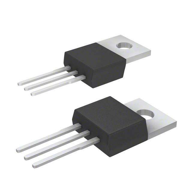
ICGOO在线商城 > 集成电路(IC) > PMIC - 稳压器 - 线性 > LM1086IS-5.0/NOPB
- 型号: LM1086IS-5.0/NOPB
- 制造商: Texas Instruments
- 库位|库存: xxxx|xxxx
- 要求:
| 数量阶梯 | 香港交货 | 国内含税 |
| +xxxx | $xxxx | ¥xxxx |
查看当月历史价格
查看今年历史价格
LM1086IS-5.0/NOPB产品简介:
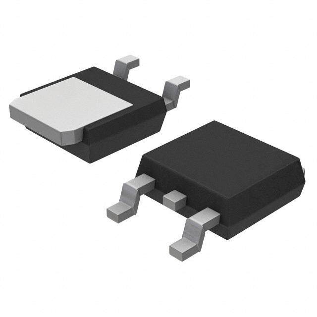
ICGOO电子元器件商城为您提供LM1086IS-5.0/NOPB由Texas Instruments设计生产,在icgoo商城现货销售,并且可以通过原厂、代理商等渠道进行代购。 LM1086IS-5.0/NOPB价格参考。Texas InstrumentsLM1086IS-5.0/NOPB封装/规格:PMIC - 稳压器 - 线性, Linear Voltage Regulator IC Positive Fixed 1 Output 5V 1.5A DDPAK/TO-263-3。您可以下载LM1086IS-5.0/NOPB参考资料、Datasheet数据手册功能说明书,资料中有LM1086IS-5.0/NOPB 详细功能的应用电路图电压和使用方法及教程。
| 参数 | 数值 |
| 产品目录 | 集成电路 (IC)半导体 |
| 描述 | IC REG LDO 5V 1.5A DDPAK低压差稳压器 1.5A LDO Pos Regs |
| 产品分类 | |
| 品牌 | Texas Instruments |
| 产品手册 | |
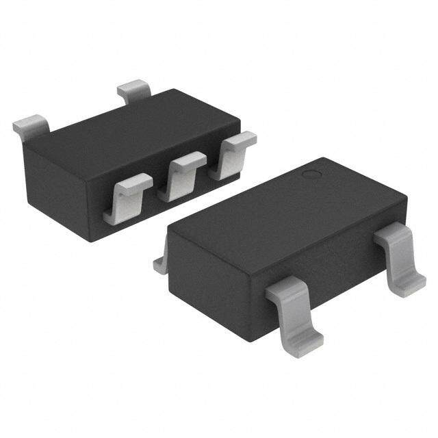
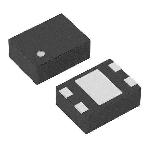
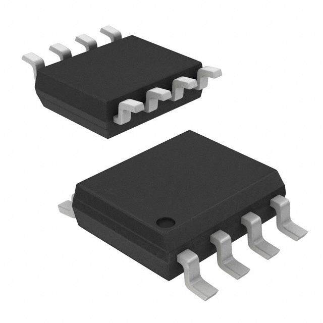
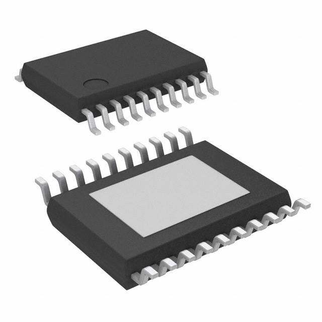
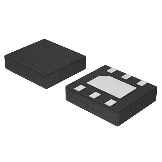
| 产品图片 |
|
| rohs | 符合RoHS含铅 / 不受限制有害物质指令(RoHS)规范要求限制 |
| 产品系列 | 电源管理 IC,低压差稳压器,Texas Instruments LM1086IS-5.0/NOPB- |
| 数据手册 | |
| 产品型号 | LM1086IS-5.0/NOPB |
| PSRR/纹波抑制—典型值 | 68 dB |
| 产品 | Low Dropout Linear Regulator |
| 产品目录页面 | |
| 产品种类 | 低压差稳压器 |
| 供应商器件封装 | DDPAK/TO-263-3 |
| 其它名称 | *LM1086IS-5.0 |
| 制造商产品页 | http://www.ti.com/general/docs/suppproductinfo.tsp?distId=10&orderablePartNumber=LM1086IS-5.0/NOPB |
| 包装 | 管件 |
| 商标 | Texas Instruments |
| 回动电压—最大值 | 1.5 V |
| 安装类型 | 表面贴装 |
| 安装风格 | SMD/SMT |
| 封装 | Tube |
| 封装/外壳 | TO-263-4,D²Pak(3 引线+接片),TO-263AA |
| 封装/箱体 | TO-263-3 |
| 工作温度 | -40°C ~ 125°C |
| 工厂包装数量 | 45 |
| 最大工作温度 | + 125 C |
| 最大输入电压 | 25 V |
| 最小工作温度 | - 40 C |
| 最小输入电压 | 2.6 V |
| 标准包装 | 45 |
| 电压-跌落(典型值) | 1.3V @ 1.5A |
| 电压-输入 | 最高 25V |
| 电压-输出 | 5V |
| 电压调节准确度 | 1.5 % |
| 电流-输出 | 1.5A |
| 电流-限制(最小值) | 1.5A |
| 稳压器拓扑 | 正,固定式 |
| 稳压器数 | 1 |
| 类型 | Low Dropout Positive Regulator |
| 系列 | LM1086 |
| 线路调整率 | 0.5 mV |
| 设计资源 | http://www.digikey.com/product-highlights/cn/zh/texas-instruments-webench-design-center/3176 |
| 负载调节 | 5 mV |
| 输出电压 | 5 V |
| 输出电流 | 1.5 A |
| 输出端数量 | 1 Output |
| 输出类型 | Fixed |


PDF Datasheet 数据手册内容提取
Product Sample & Technical Tools & Support & Folder Buy Documents Software Community LM1086 SNVS039J–JUNE2000–REVISEDAPRIL2015 LM1086 1.5-A Low Dropout Positive Regulators 1 Features 3 Description • Availablein1.8-V,2.5-V,3.3-V,5-Vand The LM1086 is a regulator with a maximum dropout 1 of 1.5 V at 1.5 A of load current. The device has the AdjustableVersions samepin-outasTI'sindustrystandardLM317. • CurrentLimitingandThermalProtection Two resistors are required to set the output voltage of • OutputCurrent1.5A the adjustable output voltage version of the LM1086. • LineRegulation0.015%(Typical) Fixed output voltage versions integrate the adjust • LoadRegulation0.1%(Typical) resistors. The LM1086 circuit includes a zener trimmed 2 Applications bandgap reference, current limiting, and thermal • High-EfficiencyLinearRegulators shutdown. • BatteryChargers Refer to LM1084 for the 5-A version, and the LM1085 • PostRegulationforSwitchingSupplies forthe3-Aversion. • ConstantCurrentRegulators DeviceInformation(1) • MicroprocessorSupplies PARTNUMBER PACKAGE BODYSIZE(NOM) WSON(8) 4mm×4mm LM1086 DDPAK/TO-263(3) 10.18mm×8.41mm TO-220(3) 14.986mm×10.16mm (1) For all available packages, see the orderable addendum at theendofthedatasheet. TypicalApplication 1 An IMPORTANT NOTICE at the end of this data sheet addresses availability, warranty, changes, use in safety-critical applications, intellectualpropertymattersandotherimportantdisclaimers.PRODUCTIONDATA.
LM1086 SNVS039J–JUNE2000–REVISEDAPRIL2015 www.ti.com Table of Contents 1 Features.................................................................. 1 7.4 DeviceFunctionalModes........................................11 2 Applications........................................................... 1 8 ApplicationandImplementation........................ 13 3 Description............................................................. 1 8.1 ApplicationInformation............................................13 4 RevisionHistory..................................................... 2 8.2 TypicalApplications................................................13 5 PinConfigurationandFunctions......................... 3 9 PowerSupplyRecommendations...................... 18 6 Specifications......................................................... 4 10 Layout................................................................... 18 6.1 AbsoluteMaximumRatings......................................4 10.1 LayoutGuidelines.................................................18 6.2 ESDRatings ............................................................4 10.2 LayoutExample....................................................18 6.3 RecommendedOperatingConditions.......................4 10.3 ThermalConsiderations........................................19 6.4 ThermalInformation..................................................5 11 DeviceandDocumentationSupport................. 21 6.5 ElectricalCharacteristics...........................................5 11.1 DevelopmentSupport...........................................21 6.6 TypicalCharacteristics..............................................7 11.2 Trademarks...........................................................21 7 DetailedDescription.............................................. 9 11.3 ElectrostaticDischargeCaution............................21 7.1 Overview...................................................................9 11.4 Glossary................................................................21 7.2 FunctionalBlockDiagram.........................................9 12 Mechanical,Packaging,andOrderable Information........................................................... 21 7.3 FeatureDescription.................................................10 4 Revision History ChangesfromRevisionI(August2014)toRevisionJ Page • Added8-pinWSONpinoutdrawingandassociateddeviceinformation................................................................................ 3 ChangesfromRevisionH(May2013)toRevisionI Page • AddedESDRatingstable,FeatureDescriptionsection,DeviceFunctionalModes,ApplicationandImplementation section,PowerSupplyRecommendationssection,Layoutsection,DeviceandDocumentationSupportsection,and Mechanical,Packaging,andOrderableInformationsection ................................................................................................. 4 2 SubmitDocumentationFeedback Copyright©2000–2015,TexasInstrumentsIncorporated ProductFolderLinks:LM1086
LM1086 www.ti.com SNVS039J–JUNE2000–REVISEDAPRIL2015 5 Pin Configuration and Functions 8-PinWSON PackageNGN TopView ADJ/GND 1 8 VOUT VIN 2 7 VOUT VOUT N/C 3 6 VOUT N/C 4 5 N/C 3-PinTO-220 PackageNDE TopView 3-PinDDPAK/TO-263 PackageKTT TopView PinFunctions PIN NUMBER I/O DESCRIPTION NAME KTT/NDE NGN Adjustpinfortheadjustableoutputvoltageversion.Groundpinforthefixed ADJ/GND 1 1 –– outputvoltageversions. V 2,TAB 6,7,8,PAD O Outputvoltagepinfortheregulator. OUT V 3 2 I Inputvoltagepinfortheregulator. IN N/C 3,4,5 –– NoConnection Copyright©2000–2015,TexasInstrumentsIncorporated SubmitDocumentationFeedback 3 ProductFolderLinks:LM1086
LM1086 SNVS039J–JUNE2000–REVISEDAPRIL2015 www.ti.com 6 Specifications 6.1 Absolute Maximum Ratings overoperatingfree-airtemperaturerange(unlessotherwisenoted) (1)(2) MIN MAX UNIT LM1086-ADJ 29 V LM1086-1.8 27 V MaximumInputtoOutputVoltageDifferential LM1086-2.5 27 V LM1086-3.3 27 V LM1086-5.0 25 V PowerDissipation(3) InternallyLimited JunctionTemperature(T)(4) 150 °C J LeadTemperature 260,to10sec °C Storagetemperature,T –65 150 °C stg (1) StressesbeyondthoselistedunderAbsoluteMaximumRatingsmaycausepermanentdamagetothedevice.Thesearestressratings only,whichdonotimplyfunctionaloperationofthedeviceattheseoranyotherconditionsbeyondthoseindicatedunderRecommended OperatingConditions.Exposuretoabsolute-maximum-ratedconditionsforextendedperiodsmayaffectdevicereliability. (2) IfMilitary/Aerospacespecifieddevicesarerequired,pleasecontacttheTexasInstrumentsSalesOffice/Distributorsforavailabilityand specifications. (3) Powerdissipationiskeptinasaferangebycurrentlimitingcircuitry.RefertoOverloadRecoveryinApplicationandImplementation.The valueθJAfortheWSONpackageisspecificallydependentonPCBtracearea,tracematerial,andthenumberofthermalvias.For improvedthermalresistanceandpowerdissipationfortheWSONpackage,refertoApplicationNoteAN-1187(literaturenumber SNOA401). (4) ThemaximumpowerdissipationisafunctionofT ,θ ,andT .Themaximumallowablepowerdissipationatanyambient J(MAX) JA A temperatureisP =(T –T )/θ .AllnumbersapplyforpackagessoldereddirectlyintoaPCboard.RefertoThermal D J(MAX) A JA Considerations 6.2 ESD Ratings VALUE UNIT V Electrostaticdischarge Human-bodymodel(HBM),perANSI/ESDA/JEDECJS-001(1) ±2000 V (ESD) (1) JEDECdocumentJEP155statesthat500-VHBMallowssafemanufacturingwithastandardESDcontrolprocess. 6.3 Recommended Operating Conditions MIN MAX UNIT JUNCTIONTEMPERATURERANGE(T )(1) J ControlSection 0 125 °C "C"Grade OutputSection 0 150 °C ControlSection −40 125 °C "I"Grade OutputSection −40 150 °C (1) ThemaximumpowerdissipationisafunctionofT ,θ ,andT .Themaximumallowablepowerdissipationatanyambient J(MAX) JA A temperatureisP =(T –T )/θ .AllnumbersapplyforpackagessoldereddirectlyintoaPCboard.RefertoThermal D J(MAX) A JA Considerations. 4 SubmitDocumentationFeedback Copyright©2000–2015,TexasInstrumentsIncorporated ProductFolderLinks:LM1086
LM1086 www.ti.com SNVS039J–JUNE2000–REVISEDAPRIL2015 6.4 Thermal Information LM1086 THERMALMETRIC(1) KTT NDE NGN UNIT 3PINS 3PINS 8PINS R Junction-to-ambientthermalresistance 40.8 23.0 35.9 θJA R Junction-to-case(top)thermalresistance 42.3 16.1 24.2 θJC(top) R Junction-to-boardthermalresistance 23.3 4.5 13.2 θJB ψ Junction-to-topcharacterizationparameter 10.2 2.4 0.2 °C/W JT ψ Junction-to-boardcharacterizationparameter 22.3 2.5 13.3 JB R Junction-to-case(bottom)thermalresistance:Control θJC(bot) 1.5/4.0 1.5/4.0 2.9 Section/OutputSection (1) Formoreinformationabouttraditionalandnewthermalmetrics,seetheICPackageThermalMetricsapplicationreport,SPRA953. 6.5 Electrical Characteristics TypicalsandlimitsappearinginnormaltypeapplyforT =25°Cunlessspecifiedotherwise. J T overtheentirerangefor J operation(see T =25°C PARAMETER TESTCONDITIONS J RecommendedOperating UNIT Conditions) MIN TYP MAX MIN(1) TYP(2) MAX (1) LM1086-ADJ,I =10mA, OUT Reference V −V =3V,10mA≤ V IN OUT 1.238 1.250 1.262 1.225 1.250 1.270 V REF Voltage I ≤I ,1.5V≤V OUT FULLLOAD IN −V ≤15V(3) OUT V OutputVoltage(3) LM1086-1.8,I =0mA,V OUT OUT IN =5V,0≤I ≤I , 1.782 1.8 1.818 1.764 1.8 1.836 V OUT FULLLOAD 3.3V≤V ≤18V IN LM1086-2.5,I =0mA,V OUT IN =5V,0≤I ≤I , 2.475 2.50 2.525 2.450 2.50 2.55 V OUT FULLLOAD 4.0V≤V ≤18V IN LM1086-3.3,I =0mA,V OUT IN =5V,0≤I ≤I , 3.267 3.300 3.333 3.235 3.300 3.365 V OUT FULLLOAD 4.75V≤V ≤18V IN LM1086-5.0,I =0mA,V OUT IN =8V,0≤I ≤I , 4.950 5.000 5.050 4.900 5.000 5.100 V OUT FULLLOAD 6.5V≤V ≤20V IN LM1086-ADJ,I =10mA, OUT 0.015% 0.2% 0.035% 0.2% 1.5V≤(V -V )≤15V IN OUT LM1086-1.8,I =0mA,3.3 OUT 0.3 6 0.6 6 mV V≤V ≤18V IN Line LM1086-2.5,I =0mA,4.0 ΔVOUT Regulation(4) V≤V ≤18VOUT 0.3 6 0.6 6 mV IN LM1086-3.3,I =0mA,4.5 OUT 0.5 10 1.0 10 mV V≤V ≤18V IN LM1086-5.0,I =0mA,6.5 OUT 0.5 10 1.0 10 mV V≤V ≤20V IN (1) Alllimitsarespecifiedbytestingorstatisticalanalysis. (2) TypicalValuesrepresentthemostlikelyparametricnorm. (3) I isdefinedinthecurrentlimitcurves.TheI Curvedefinescurrentlimitasafunctionofinput-to-outputvoltage.Note FULLLOAD FULLLOAD that15WpowerdissipationfortheLM1086isonlyachievableoveralimitedrangeofinput-to-outputvoltage. (4) Loadandlineregulationaremeasuredatconstantjunctiontemperature,andarespecifieduptothemaximumpowerdissipationof 15W.Powerdissipationisdeterminedbytheinput/outputdifferentialandtheoutputcurrent.Ensuredmaximumpowerdissipationwill notbeavailableoverthefullinput/outputrange. Copyright©2000–2015,TexasInstrumentsIncorporated SubmitDocumentationFeedback 5 ProductFolderLinks:LM1086
LM1086 SNVS039J–JUNE2000–REVISEDAPRIL2015 www.ti.com Electrical Characteristics (continued) TypicalsandlimitsappearinginnormaltypeapplyforT =25°Cunlessspecifiedotherwise. J T overtheentirerangefor J operation(see T =25°C PARAMETER TESTCONDITIONS J RecommendedOperating UNIT Conditions) MIN TYP MAX MIN(1) TYP(2) MAX (1) LM1086-ADJ,(V -V )=3 IN OUT 0.1% 0.3% 0.2% 0.4% V,10mA≤I ≤I OUT FULLLOAD LM1086-1.8,2.5,V =5V,0 IN 3 12 6 20 mV Load ≤IOUT≤IFULLLOAD ΔVOUT Regulation(4) LM1086-3.3,V =5V,0≤ IN 3 15 7 25 mV I ≤I OUT FULLLOAD LM1086-5.0,V =8V,0≤ IN 5 20 10 35 mV I ≤I OUT FULLLOAD LM1086-ADJ,1.8,2.5,3.3,5, Dropout Voltage(5) ΔVREF,ΔVOUT=1%,IOUT= 1.3 1.5 V 1.5A LM1086-ADJ,V −V =5 1.50 2.7 IN OUT V,V −V =25V A IN OUT 0.05 0.15 ILIMIT CurrentLimit LM1086-1.8,2.5,3.3,VIN=8 1.5 2.7 A V LM1086-5.0,V =10V 1.5 2.7 A IN MinimumLoad LM1086-ADJ,V −V =25 Current(6) V IN OUT 5.0 10.0 mA LM1086-1.8,2.5,V ≤18V 5.0 10.0 mA IN Quiescent LM1086-3.3,V ≤18V 5.0 10.0 mA Current IN LM1086-5.0,V ≤20V 5.0 10.0 mA IN Thermal T =25°C,30msPulse A 0.008 0.04 %/W Regulation f =120Hz,C =25 RIPPLE OUT µFTantalum,I =1.5A OUT dB LM1086-ADJ,C =25µF, ADJ (V −V )=3V 60 75 RippleRejection IN O LM1086-1.8,2.5,V =6V 60 72 dB IN LM1086-3.3,V =6.3V 60 72 dB IN LM1086-5.0V =8V 60 68 dB IN AdjustPin LM1086 55 120 µA Current AdjustPin 10mA≤I ≤I ,1.5 OUT FULLLOAD 0.2 5 µA CurrentChange V≤(V −V )≤15V IN OUT Temperature 0.5% Stability LongTerm T =125°C,1000Hrs A 0.3% 1.0% Stability RMSNoise 10Hz≤f≤10kHz 0.003% (%ofV ) OUT (5) Dropoutvoltageisspecifiedoverthefulloutputcurrentrangeofthedevice. (6) Theminimumoutputcurrentrequiredtomaintainregulation. 6 SubmitDocumentationFeedback Copyright©2000–2015,TexasInstrumentsIncorporated ProductFolderLinks:LM1086
LM1086 www.ti.com SNVS039J–JUNE2000–REVISEDAPRIL2015 6.6 Typical Characteristics Figure1.DropoutVoltagevsOutputCurrent Figure2.Short-CircuitCurrentvsInput/OutputDifference Figure3.LoadRegulationvsTemperature Figure4.PercentChangeinOutputVoltagevs Temperature Figure5.AdjustPinCurrentvsTemperature Figure6.MaximumPowerDissipationvsTemperature Copyright©2000–2015,TexasInstrumentsIncorporated SubmitDocumentationFeedback 7 ProductFolderLinks:LM1086
LM1086 SNVS039J–JUNE2000–REVISEDAPRIL2015 www.ti.com Typical Characteristics (continued) Figure7.RippleRejectionvsFrequency(LM1086-ADJ) Figure8.RippleRejectionvsOutputCurrent(LM1086- ADJ) Figure9.RippleRejectionvsFrequency(LM1086-5) Figure10.RippleRejectionvsOutputCurrent(LM1086-5) Figure11.LineTransientResponse Figure12.LoadTransientResponse 8 SubmitDocumentationFeedback Copyright©2000–2015,TexasInstrumentsIncorporated ProductFolderLinks:LM1086
LM1086 www.ti.com SNVS039J–JUNE2000–REVISEDAPRIL2015 7 Detailed Description 7.1 Overview A basic functional diagram for the LM1086-ADJ (excluding protection circuitry) is shown in Figure 13. The topology is basically that of the LM317 except for the pass transistor. Instead of a Darlingtion NPN with its two diode voltage drop, the LM1086 uses a single NPN. This results in a lower dropout voltage. The structure of the pass transistor is also known as a quasi LDO. The advantage of a quasi LDO over a PNP LDO is its inherently lower quiescent current. The LM1086 is specified to provide a minimum dropout voltage of 1.5V over temperature,atfullload. Figure13. BasicFunctionalBlockDiagram 7.2 Functional Block Diagram Copyright©2000–2015,TexasInstrumentsIncorporated SubmitDocumentationFeedback 9 ProductFolderLinks:LM1086
LM1086 SNVS039J–JUNE2000–REVISEDAPRIL2015 www.ti.com 7.3 Feature Description 7.3.1 RippleRejection Ripple rejection is a function of the open loop gain within the feed-back loop (refer to Figure 13 and Figure 16). The LM1086 exhibits 75dB of ripple rejection (typ.). When adjusted for voltages higher than V , the ripple REF rejectiondecreasesasfunctionofadjustmentgain:(1+R1/R2)orV /V .Thereforea5-Vadjustmentdecreases O REF ripplerejectionbyafactoroffour(−12dB);Outputrippleincreasesasadjustmentvoltageincreases. However, the adjustable version allows this degradation of ripple rejection to be compensated. The adjust terminal can be bypassed to ground with a capacitor (C ). The impedance of the C should be equal to or ADJ ADJ less than R1 at the desired ripple frequency. This bypass capacitor prevents ripple from being amplified as the outputvoltageisincreased. 1/(2π*f *C )≤R (1) RIPPLE ADJ 1 7.3.2 LoadRegulation The LM1086 regulates the voltage that appears between its output and ground pins, or between its output and adjust pins. In some cases, line resistances can introduce errors to the voltage across the load. To obtain the bestloadregulation,afewprecautionsareneeded. Figure 14 shows a typical application using a fixed output regulator. Rt1 and Rt2 are the line resistances. V LOAD is less than the V by the sum of the voltage drops along the line resistances. In this case, the load regulation OUT seen at the R would be degraded from the data sheet specification. To improve this, the load should be tied LOAD directlytotheoutputterminalonthepositivesideanddirectlytiedtothegroundterminalonthenegativeside. Figure14. TypicalApplicationUsingFixedOutputRegulator When the adjustable regulator is used (Figure 15), the best performance is obtained with the positive side of the resistorR1tieddirectlytotheoutputterminaloftheregulatorratherthanneartheload.Thiseliminateslinedrops fromappearingeffectivelyinserieswiththereferenceanddegradingregulation.Forexample,a5Vregulatorwith 0.05-Ω resistancebetweentheregulatorandloadwillhavealoadregulationduetolineresistanceof0.05 Ω ×I . L If R1 (=125 Ω) is connected near the load the effective line resistance will be 0.05 Ω (1 + R2/R1) or in this case, it is 4 times worse. In addition, the ground side of the resistor R2 can be returned near the ground of the load to provideremotegroundsensingandimproveloadregulation. Figure15. BestLoadRegulationUsingAdjustableOutputRegulator 10 SubmitDocumentationFeedback Copyright©2000–2015,TexasInstrumentsIncorporated ProductFolderLinks:LM1086
LM1086 www.ti.com SNVS039J–JUNE2000–REVISEDAPRIL2015 Feature Description (continued) 7.3.3 OverloadRecovery Overloadrecoveryreferstoregulator'sabilitytorecoverfromashortcircuitedoutput.Akeyfactorintherecovery processisthecurrentlimitingusedtoprotecttheoutputfromdrawingtoomuchpower.Thecurrentlimitingcircuit reduces the output current as the input to output differential increases. Refer to short circuit curve in the Typical Characteristicssection. During normal start-up, the input to output differential is small since the output follows the input. But, if the output is shorted, then the recovery involves a large input to output differential. Sometimes during this condition the current limiting circuit is slow in recovering. If the limited current is too low to develop a voltage at the output, the voltage will stabilize at a lower level. Under these conditions it may be necessary to recycle the power of the regulator in order to get the smaller differential voltage and thus adequate start up conditions. Refer to Typical Characteristicssectionfortheshortcircuitcurrentvs.inputdifferentialvoltage. 7.4 Device Functional Modes 7.4.1 OutputVoltage The LM1086 adjustable version develops a 1.25-V reference voltage, (V ), between the output and the adjust REF terminal. As shown in Figure 16, this voltage is applied across resistor R1 to generate a constant current I1. This constant current then flows through R2. The resulting voltage drop across R2 adds to the reference voltage to setsthedesiredoutputvoltage. The current I from the adjustment terminal introduces an output error . But since it is small (120uA max), it ADJ becomesnegligiblewhenR1isinthe100Ω range. Forfixedvoltagedevices,R1andR2areintegratedinsidethedevices. Figure16. BasicAdjustableRegulator 7.4.2 StabilityConsideration Stability consideration primarily concerns the phase response of the feedback loop. In order for stable operation, the loop must maintain negative feedback. The LM1086 requires a certain amount series resistance with capacitive loads. This series resistance introduces a zero within the loop to increase phase margin and thus increase stability. The equivalent series resistance (ESR) of solid tantalum or aluminum electrolytic capacitors is usedtoprovidetheappropriatezero(approximately500kHz). Aluminum electrolytics are less expensive than tantalums, but their ESR varies exponentially at cold temperatures; therefore requiring close examination when choosing the desired transient response over temperature.TantalumsareaconvenientchoicebecausetheirESRvarieslessthan2:1overtemperature. The recommended load/decoupling capacitance is a 10 uF tantalum or a 50 uF aluminum. These values will assurestabilityforthemajorityofapplications. The adjustable versions allows an additional capacitor to be used at the ADJ pin to increase ripple rejection. If thisisdonetheoutputcapacitorshouldbeincreasedto22uFfortantalumorto150uFforaluminum. Capacitors other than tantalum or aluminum can be used at the adjust pin and the input pin. A 10 uF capacitor is areasonablevalueattheinput.SeeRippleRejection sectionregardingthevaluefortheadjustpincapacitor. Copyright©2000–2015,TexasInstrumentsIncorporated SubmitDocumentationFeedback 11 ProductFolderLinks:LM1086
LM1086 SNVS039J–JUNE2000–REVISEDAPRIL2015 www.ti.com Device Functional Modes (continued) It is desirable to have large output capacitance for applications that entail large changes in load current (microprocessorsforexample).Thehigherthecapacitance,thelargertheavailablechargeperdemand.Itisalso desirabletoprovidelowESRtoreducethechangeinoutputvoltage: ΔV=ΔIxESR (2) It is common practice to use several tantalum and ceramic capacitors in parallel to reduce this change in the outputvoltagebyreducingtheoverallESR. Outputcapacitancecanbeincreasedindefinitelytoimprovetransientresponseandstability. 7.4.3 ProtectionDiodes Under normal operation, the LM1086 regulator does not need any protection diode. With the adjustable device, the internal resistance between the adjustment and output terminals limits the current. No diode is needed to divert the current around the regulator even with a capacitor on the adjustment terminal. The adjust pin can take atransientsignalof±25Vwithrespecttotheoutputvoltagewithoutdamagingthedevice. When an output capacitor is connected to a regulator and the input is shorted, the output capacitor will discharge into the output of the regulator. The discharge current depends on the value of the capacitor, the output voltage of the regulator, and rate of decrease of V . In the LM1086 regulator, the internal diode between the output and IN input pins can withstand microsecond surge currents of 10 A to 20 A. With an extremely large output capacitor (≥1000 µf), and with input instantaneously shorted to ground, the regulator could be damaged. In this case, an externaldiodeisrecommendedbetweentheoutputandinputpinstoprotecttheregulator,showninFigure17. Figure17. RegulatorwithProtectionDiode 12 SubmitDocumentationFeedback Copyright©2000–2015,TexasInstrumentsIncorporated ProductFolderLinks:LM1086
LM1086 www.ti.com SNVS039J–JUNE2000–REVISEDAPRIL2015 8 Application and Implementation NOTE Information in the following applications sections is not part of the TI component specification, and TI does not warrant its accuracy or completeness. TI’s customers are responsible for determining suitability of components for their purposes. Customers should validateandtesttheirdesignimplementationtoconfirmsystemfunctionality. 8.1 Application Information The LM1086 is versatile in its applications, including uses in programmable output regulation and local on-card regulation. Or, by connecting a fixed resistor between the ADJUST and OUTPUT terminals, the LM1086 can function as a precision current regulator. An optional output capacitor can be added to improve transient response. The ADJUST terminal can be bypassed to achieve very high ripple-rejection ratios, which are difficult toachievewithstandardthree-terminalregulators.Pleasenote,inthefollowingapplications,ifADJismentioned, it makes use of the adjustable version of the part, however, if GND is mentioned, it is the fixed voltage version of thepart. 8.2 Typical Applications 8.2.1 1.2-Vto15-VAdjustableRegulator This part can be used as a simple low drop out regulator to enable a variety of output voltages needed for demanding applications. By using an adjustable R2 resistor a variety of output voltages can be made possible as showninFigure18basedontheLM1086-ADJ. Figure18. 1.2-Vto15-VAdjustableRegulator 8.2.1.1 DesignRequirements The device component count is very minimal, employing two resistors as part of a voltage divider circuit and an outputcapacitorforloadregulation. 8.2.1.2 DetailedDesignProcedure ThevoltagedividerforthispartissetbasedontheequationshowninFigure18,whereR1istheupperfeedback resistorR2isthelowerfeedbackresistor. Copyright©2000–2015,TexasInstrumentsIncorporated SubmitDocumentationFeedback 13 ProductFolderLinks:LM1086
LM1086 SNVS039J–JUNE2000–REVISEDAPRIL2015 www.ti.com Typical Applications (continued) 8.2.1.3 ApplicationCurve 8.2.2 Adjustableat5V The application shown in Figure 19 outlines a simple 5-V output application made possible by the LM1086-ADJ. Thisapplicationcanprovide1.5Aathighefficienciesandverylowdrop-out. Figure19. Adjustableat5V 8.2.3 5-VRegulatorwithShutdown A variation of the 5-V output regulator application with shutdown control is shown in Figure 20 based on the LM1086-ADJ. It uses a simple NPN transistor on the ADJ pin to block or sink the current on the ADJ pin. If the TTL logic is pulled high, the NPN transistor is activated and the part is disabled, outputting approximately 1.25 V. IftheTTLlogicispulledlow,theNPNtransistorisunbiasedandtheregulatorfunctionsnormally. Figure20. 5-VRegulatorwithShutdown 14 SubmitDocumentationFeedback Copyright©2000–2015,TexasInstrumentsIncorporated ProductFolderLinks:LM1086
LM1086 www.ti.com SNVS039J–JUNE2000–REVISEDAPRIL2015 Typical Applications (continued) 8.2.4 BatteryCharger The LM1086-ADJ can be used as a battery charger to regulate the charging current required by the battery bank as shown in Figure 21. In this application the LM1086 acts as a constant voltage, constant current part by sensing the voltage potential across the battery and compensating it to the current voltage. To maintain this voltage, the regulator delivers the maximum charging current required to charge the battery. As the battery approaches the fully charged state, the potential drop across the sense resistor, R reduces and the regulator S throttlesbackthecurrenttomaintainthefloatvoltageofthebattery. Figure21. BatteryCharger 8.2.5 AdjustableFixedRegulator A simple adjustable, fixed range output regulator can be made possible by placing a variable resistor on the ground of the device as shown in Figure 22 based on the fixed output voltage LM1086-5.0. The GND pin has a small quiescent current of 5 mA typical. Increasing the resistance on the GND pin increases the voltage potential across the resistor. This potential is then mirrored on to the output to increase the total output voltage by the potentialdropacrosstheGNDresistor. Figure22. AdjustableFixedRegulator 8.2.6 RegulatorWithReference A fixed output voltage version of the LM1086-5.0 can be employed to provide an output rail and a reference rail at the same time as shown in Figure 23. This simple application makes use of a reference diode, the LM136-5, to regulate the GND voltage to a fixed 5 V based on the quiescent current generated by the GND pin. This voltageisthenaddedontotheoutputtogenerateatotalof10Vout. Figure23. RegulatorWithReference Copyright©2000–2015,TexasInstrumentsIncorporated SubmitDocumentationFeedback 15 ProductFolderLinks:LM1086
LM1086 SNVS039J–JUNE2000–REVISEDAPRIL2015 www.ti.com Typical Applications (continued) 8.2.7 HighCurrentLampDriverProtection A simple constant current source with protection can be designed by controlling the impedance between the lamp and ground. The LM1086-ADJ shown in Figure 24 makes use of an external TTL or CMOS input to drive the NPN transistor. This pulls the output of the regulator to a few tenths of a volt and puts the part into current limit. Releasing the logic will reduce the current flow across the lamp into the normal operating current thereby protectingthelampduringstartup. Figure24. HighCurrentLampDriverProtection 8.2.8 BatteryBackupRegulatedSupply A regulated battery backup supply can be generated by using two fixed output voltage versions of the part as showninFigure25.ThetopregulatorsuppliestheLinevoltageduringnormaloperation,howeverwhentheinput is not available, the second regulator derives power from the battery backup and regulates it to 5 V based on the LM1086-5.0.Thediodespreventtherailsfrombackfeedingintothesupplyandbatteries. Figure25. BatteryBackupRegulatedSupply 16 SubmitDocumentationFeedback Copyright©2000–2015,TexasInstrumentsIncorporated ProductFolderLinks:LM1086
LM1086 www.ti.com SNVS039J–JUNE2000–REVISEDAPRIL2015 Typical Applications (continued) 8.2.9 RippleRejectionEnhancement A very simple ripple rejection circuit is shown in Figure 26 using the LM1086-ADJ. The capacitor C1 smooths out therippleontheoutputbycleaningupthefeedbackpathandpreventingexcessnoisefromfeedingbackintothe regulator.PleaserememberX shouldbeapproximatelyequaltoR1attheripplefrequency. C1 Figure26. RippleRejectionEnhancement 8.2.10 AutomaticLightControl A common street light control or automatic light control circuit is designed in Figure 27 based on the LM1086- ADJ. The photo transistor conducts in the presence of light and grounds the ADJ pin preventing the lamp from turning on. However, in the absence of light, the LM1086 regulates the voltage to 1.25 V between OUT and ADJ, ensuringthelampremainson. Figure27. AutomaticLightControl 8.2.11 RemoteSensing Remote sensing is a method of compensating the output voltage to a very precise degree by sensing the output and feeding it back through the feedback. The circuit implementing this is shown in Figure 28 using the LM1086- ADJ. The output of the regulator is fed into a voltage follower to avoid any loading effects and the output of the op-ampisinjectedintothetopofthefeedbackresistornetwork.Thishastheeffectofmodulatingthevoltagetoa precisedegreewithoutadditionalloadingontheoutput. Figure28. RemoteSensing Copyright©2000–2015,TexasInstrumentsIncorporated SubmitDocumentationFeedback 17 ProductFolderLinks:LM1086
LM1086 SNVS039J–JUNE2000–REVISEDAPRIL2015 www.ti.com 9 Power Supply Recommendations The linear regulator input supply should be well regulated and kept at a voltage level such that the maximum input to output voltage differential allowed by the device is not exceeded. The minimum dropout voltage (V – IN V ) should be met with extra headroom when possible in order to keep the output well regulated. A 10 μF or OUT highercapacitorshouldbeplacedattheinputtobypassnoise. 10 Layout 10.1 Layout Guidelines For the best overall performance, some layout guidelines should be followed. Place all circuit components on the samesideofthecircuitboardandasnearaspracticaltotherespectivelinearregulatorpinsconnections.Traces should be kept short and wide to reduce the amount of parasitic elements into the system. The actual width and thickness of traces will depend on the current carrying capability and heat dissipation required by the end system. An array of plated vias can be placed on the pad area underneath the TAB to conduct heat to any inner planeareasortoabottom-sidecopperplane. 10.2 Layout Example Figure29. LayoutExample 18 SubmitDocumentationFeedback Copyright©2000–2015,TexasInstrumentsIncorporated ProductFolderLinks:LM1086
LM1086 www.ti.com SNVS039J–JUNE2000–REVISEDAPRIL2015 10.3 Thermal Considerations ICs heats up when in operation, and power consumption is one factor in how hot it gets. The other factor is how well the heat is dissipated. Heat dissipation is predictable by knowing the thermal resistance between the IC and ambient (θ ). Thermal resistance has units of temperature per power (C/W). The higher the thermal resistance, JA thehottertheIC. The LM1086 specifies the thermal resistance for each package as junction to case (θ ). In order to get the total JC resistance to ambient (θ ), two other thermal resistance must be added, one for case to heat-sink (θ ) and one JA CH forheatsinktoambient(θ ).Thejunctiontemperaturecanbepredictedasfollows: HA T =T +P (θ +θ +θ )=T +P θ J A D JC CH HA A D JA where • T isjunctiontemperature J • T isambienttemperature A • P isthepowerconsumptionofthedevice (3) D Devicepowerconsumptioniscalculatedasfollows: I =I +I (4) IN L G P =(V −V )I +V I (5) D IN OUT L ING Figure30showsthevoltagesandcurrentswhicharepresentinthecircuit. Figure30. PowerDissipationDiagram Oncethedevicespowerisdetermined,themaximumallowable(θ )iscalculatedas: JA(max) θ =T /P =T − T /P JA(max) R(max) D J(max) A(max) D The LM1086 has different temperature specifications for two different sections of the IC: the control section and the output section. The Thermal Information table shows the junction to case thermal resistances for each of these sections, while the maximum junction temperatures (T ) for each section is listed in the Absolute J(max) Maximum Ratings section of the datasheet. T is 125°C for the control section, while T is 150°C for the J(max) J(max) outputsection. θ shouldbecalculatedseparatelyforeachsectionasfollows: JA(max) θ (max,CONTROLSECTION)=(125°C-T )/P (6) JA A(max) D θ (max,OUTPUTSECTION)=(150°C-T )/P (7) JA A(max) D Therequiredheatsinkisdeterminedbycalculatingitsrequiredthermalresistance(θ ). HA(max) θ =θ −(θ +θ ) (8) HA(max) JA(max) JC CH (θ )shouldalsobecalculatedtwiceasfollows: HA (max) (θ )=θ (max,CONTROLSECTION)-(θ (CONTROLSECTION)+θ ) (9) HA(max) JA JC CH (θ )=θ (max,OUTPUTSECTION)-(θ (OUTPUTSECTION)+θ ) (10) HA(max) JA JC CH If thermal compound is used, θ can be estimated at 0.2 C/W. If the case is soldered to the heat sink, then a CH θ canbeestimatedas0C/W. CH After, θ is calculated for each section, choose the lower of the two θ values to determine the HA (max) HA (max) appropriateheatsink. Copyright©2000–2015,TexasInstrumentsIncorporated SubmitDocumentationFeedback 19 ProductFolderLinks:LM1086
LM1086 SNVS039J–JUNE2000–REVISEDAPRIL2015 www.ti.com Thermal Considerations (continued) If PC board copper is going to be used as a heat sink, then Figure 31 can be used to determine the appropriate area(size)ofcopperfoilrequired. Figure31. HeatSinkThermalResistancevsArea 20 SubmitDocumentationFeedback Copyright©2000–2015,TexasInstrumentsIncorporated ProductFolderLinks:LM1086
LM1086 www.ti.com SNVS039J–JUNE2000–REVISEDAPRIL2015 11 Device and Documentation Support 11.1 Development Support Foradditionalinformation,seeTexasInstruments'E2Ecommunityresourcesathttp://e2e.ti.com. 11.2 Trademarks Alltrademarksarethepropertyoftheirrespectiveowners. 11.3 Electrostatic Discharge Caution Thesedeviceshavelimitedbuilt-inESDprotection.Theleadsshouldbeshortedtogetherorthedeviceplacedinconductivefoam duringstorageorhandlingtopreventelectrostaticdamagetotheMOSgates. 11.4 Glossary SLYZ022—TIGlossary. Thisglossarylistsandexplainsterms,acronyms,anddefinitions. 12 Mechanical, Packaging, and Orderable Information The following pages include mechanical, packaging, and orderable information. This information is the most current data available for the designated devices. This data is subject to change without notice and revision of thisdocument.Forbrowser-basedversionsofthisdatasheet,refertotheleft-handnavigation. Copyright©2000–2015,TexasInstrumentsIncorporated SubmitDocumentationFeedback 21 ProductFolderLinks:LM1086
PACKAGE OPTION ADDENDUM www.ti.com 29-Jun-2017 PACKAGING INFORMATION Orderable Device Status Package Type Package Pins Package Eco Plan Lead/Ball Finish MSL Peak Temp Op Temp (°C) Device Marking Samples (1) Drawing Qty (2) (6) (3) (4/5) LM1086CS-2.5/NOPB ACTIVE DDPAK/ KTT 3 45 Pb-Free (RoHS CU SN Level-3-245C-168 HR 0 to 125 LM1086 TO-263 Exempt) CS-2.5 LM1086CS-3.3/NOPB ACTIVE DDPAK/ KTT 3 45 Pb-Free (RoHS CU SN Level-3-245C-168 HR 0 to 125 LM1086 TO-263 Exempt) CS-3.3 LM1086CS-5.0/NOPB ACTIVE DDPAK/ KTT 3 45 Pb-Free (RoHS CU SN Level-3-245C-168 HR 0 to 125 LM1086 TO-263 Exempt) CS-5.0 LM1086CS-ADJ NRND DDPAK/ KTT 3 45 TBD Call TI Call TI LM1086 TO-263 CS-ADJ LM1086CS-ADJ/NOPB ACTIVE DDPAK/ KTT 3 45 Pb-Free (RoHS CU SN Level-3-245C-168 HR 0 to 125 LM1086 TO-263 Exempt) CS-ADJ LM1086CSX-2.5/NOPB ACTIVE DDPAK/ KTT 3 500 Pb-Free (RoHS CU SN Level-3-245C-168 HR 0 to 125 LM1086 TO-263 Exempt) CS-2.5 LM1086CSX-3.3/NOPB ACTIVE DDPAK/ KTT 3 500 Pb-Free (RoHS CU SN Level-3-245C-168 HR 0 to 125 LM1086 TO-263 Exempt) CS-3.3 LM1086CSX-ADJ/NOPB ACTIVE DDPAK/ KTT 3 500 Pb-Free (RoHS CU SN Level-3-245C-168 HR 0 to 125 LM1086 TO-263 Exempt) CS-ADJ LM1086CT-3.3/NOPB ACTIVE TO-220 NDE 3 45 Green (RoHS CU SN Level-1-NA-UNLIM 0 to 125 LM1086 & no Sb/Br) CT-3.3 LM1086CT-5.0/NOPB ACTIVE TO-220 NDE 3 45 Green (RoHS CU SN Level-1-NA-UNLIM 0 to 125 LM1086 & no Sb/Br) CT-5.0 LM1086CT-ADJ/NOPB ACTIVE TO-220 NDE 3 45 Green (RoHS CU SN Level-1-NA-UNLIM 0 to 125 LM1086 & no Sb/Br) CT-ADJ LM1086ILD-3.3/NOPB ACTIVE WSON NGN 8 1000 Green (RoHS CU SN Level-3-260C-168 HR -40 to 125 1086I33 & no Sb/Br) LM1086IS-1.8/NOPB ACTIVE DDPAK/ KTT 3 45 Pb-Free (RoHS CU SN Level-3-245C-168 HR -40 to 125 LM1086 TO-263 Exempt) IS-1.8 LM1086IS-3.3 NRND DDPAK/ KTT 3 45 TBD Call TI Call TI -40 to 125 LM1086 TO-263 IS-3.3 LM1086IS-3.3/NOPB ACTIVE DDPAK/ KTT 3 45 Pb-Free (RoHS CU SN Level-3-245C-168 HR -40 to 125 LM1086 TO-263 Exempt) IS-3.3 LM1086IS-5.0 ACTIVE DDPAK/ KTT 3 45 TBD Call TI Call TI -40 to 125 LM1086 TO-263 IS-5.0 LM1086IS-5.0/NOPB ACTIVE DDPAK/ KTT 3 45 Pb-Free (RoHS CU SN Level-3-245C-168 HR -40 to 125 LM1086 TO-263 Exempt) IS-5.0 Addendum-Page 1
PACKAGE OPTION ADDENDUM www.ti.com 29-Jun-2017 Orderable Device Status Package Type Package Pins Package Eco Plan Lead/Ball Finish MSL Peak Temp Op Temp (°C) Device Marking Samples (1) Drawing Qty (2) (6) (3) (4/5) LM1086IS-ADJ/NOPB ACTIVE DDPAK/ KTT 3 45 Pb-Free (RoHS CU SN Level-3-245C-168 HR -40 to 125 LM1086 TO-263 Exempt) IS-ADJ LM1086ISX-1.8/NOPB ACTIVE DDPAK/ KTT 3 500 Pb-Free (RoHS CU SN Level-3-245C-168 HR -40 to 125 LM1086 TO-263 Exempt) IS-1.8 LM1086ISX-3.3/NOPB ACTIVE DDPAK/ KTT 3 500 Pb-Free (RoHS CU SN Level-3-245C-168 HR -40 to 125 LM1086 TO-263 Exempt) IS-3.3 LM1086ISX-5.0/NOPB ACTIVE DDPAK/ KTT 3 500 Pb-Free (RoHS CU SN Level-3-245C-168 HR -40 to 125 LM1086 TO-263 Exempt) IS-5.0 LM1086ISX-ADJ/NOPB ACTIVE DDPAK/ KTT 3 500 Pb-Free (RoHS CU SN Level-3-245C-168 HR -40 to 125 LM1086 TO-263 Exempt) IS-ADJ LM1086IT-3.3/NOPB ACTIVE TO-220 NDE 3 45 Green (RoHS CU SN Level-1-NA-UNLIM -40 to 125 LM1086 & no Sb/Br) IT-3.3 LM1086IT-5.0/NOPB ACTIVE TO-220 NDE 3 45 Green (RoHS CU SN Level-1-NA-UNLIM -40 to 125 LM1086 & no Sb/Br) IT-5.0 LM1086IT-ADJ/NOPB ACTIVE TO-220 NDE 3 45 Green (RoHS CU SN Level-1-NA-UNLIM -40 to 125 LM1086 & no Sb/Br) IT-ADJ (1) The marketing status values are defined as follows: ACTIVE: Product device recommended for new designs. LIFEBUY: TI has announced that the device will be discontinued, and a lifetime-buy period is in effect. NRND: Not recommended for new designs. Device is in production to support existing customers, but TI does not recommend using this part in a new design. PREVIEW: Device has been announced but is not in production. Samples may or may not be available. OBSOLETE: TI has discontinued the production of the device. (2) RoHS: TI defines "RoHS" to mean semiconductor products that are compliant with the current EU RoHS requirements for all 10 RoHS substances, including the requirement that RoHS substance do not exceed 0.1% by weight in homogeneous materials. Where designed to be soldered at high temperatures, "RoHS" products are suitable for use in specified lead-free processes. TI may reference these types of products as "Pb-Free". RoHS Exempt: TI defines "RoHS Exempt" to mean products that contain lead but are compliant with EU RoHS pursuant to a specific EU RoHS exemption. Green: TI defines "Green" to mean the content of Chlorine (Cl) and Bromine (Br) based flame retardants meet JS709B low halogen requirements of <=1000ppm threshold. Antimony trioxide based flame retardants must also meet the <=1000ppm threshold requirement. (3) MSL, Peak Temp. - The Moisture Sensitivity Level rating according to the JEDEC industry standard classifications, and peak solder temperature. (4) There may be additional marking, which relates to the logo, the lot trace code information, or the environmental category on the device. (5) Multiple Device Markings will be inside parentheses. Only one Device Marking contained in parentheses and separated by a "~" will appear on a device. If a line is indented then it is a continuation of the previous line and the two combined represent the entire Device Marking for that device. Addendum-Page 2
PACKAGE OPTION ADDENDUM www.ti.com 29-Jun-2017 (6) Lead/Ball Finish - Orderable Devices may have multiple material finish options. Finish options are separated by a vertical ruled line. Lead/Ball Finish values may wrap to two lines if the finish value exceeds the maximum column width. Important Information and Disclaimer:The information provided on this page represents TI's knowledge and belief as of the date that it is provided. TI bases its knowledge and belief on information provided by third parties, and makes no representation or warranty as to the accuracy of such information. Efforts are underway to better integrate information from third parties. TI has taken and continues to take reasonable steps to provide representative and accurate information but may not have conducted destructive testing or chemical analysis on incoming materials and chemicals. TI and TI suppliers consider certain information to be proprietary, and thus CAS numbers and other limited information may not be available for release. In no event shall TI's liability arising out of such information exceed the total purchase price of the TI part(s) at issue in this document sold by TI to Customer on an annual basis. Addendum-Page 3
PACKAGE MATERIALS INFORMATION www.ti.com 20-Sep-2016 TAPE AND REEL INFORMATION *Alldimensionsarenominal Device Package Package Pins SPQ Reel Reel A0 B0 K0 P1 W Pin1 Type Drawing Diameter Width (mm) (mm) (mm) (mm) (mm) Quadrant (mm) W1(mm) LM1086CSX-2.5/NOPB DDPAK/ KTT 3 500 330.0 24.4 10.75 14.85 5.0 16.0 24.0 Q2 TO-263 LM1086CSX-3.3/NOPB DDPAK/ KTT 3 500 330.0 24.4 10.75 14.85 5.0 16.0 24.0 Q2 TO-263 LM1086CSX-ADJ/NOPB DDPAK/ KTT 3 500 330.0 24.4 10.75 14.85 5.0 16.0 24.0 Q2 TO-263 LM1086ILD-3.3/NOPB WSON NGN 8 1000 178.0 12.4 4.3 4.3 1.3 8.0 12.0 Q1 LM1086ISX-1.8/NOPB DDPAK/ KTT 3 500 330.0 24.4 10.75 14.85 5.0 16.0 24.0 Q2 TO-263 LM1086ISX-3.3/NOPB DDPAK/ KTT 3 500 330.0 24.4 10.75 14.85 5.0 16.0 24.0 Q2 TO-263 LM1086ISX-5.0/NOPB DDPAK/ KTT 3 500 330.0 24.4 10.75 14.85 5.0 16.0 24.0 Q2 TO-263 LM1086ISX-ADJ/NOPB DDPAK/ KTT 3 500 330.0 24.4 10.75 14.85 5.0 16.0 24.0 Q2 TO-263 PackMaterials-Page1
PACKAGE MATERIALS INFORMATION www.ti.com 20-Sep-2016 *Alldimensionsarenominal Device PackageType PackageDrawing Pins SPQ Length(mm) Width(mm) Height(mm) LM1086CSX-2.5/NOPB DDPAK/TO-263 KTT 3 500 367.0 367.0 45.0 LM1086CSX-3.3/NOPB DDPAK/TO-263 KTT 3 500 367.0 367.0 45.0 LM1086CSX-ADJ/NOPB DDPAK/TO-263 KTT 3 500 367.0 367.0 45.0 LM1086ILD-3.3/NOPB WSON NGN 8 1000 210.0 185.0 35.0 LM1086ISX-1.8/NOPB DDPAK/TO-263 KTT 3 500 367.0 367.0 45.0 LM1086ISX-3.3/NOPB DDPAK/TO-263 KTT 3 500 367.0 367.0 45.0 LM1086ISX-5.0/NOPB DDPAK/TO-263 KTT 3 500 367.0 367.0 45.0 LM1086ISX-ADJ/NOPB DDPAK/TO-263 KTT 3 500 367.0 367.0 45.0 PackMaterials-Page2
MECHANICAL DATA NDE0003B www.ti.com
MECHANICAL DATA KTT0003B TS3B (Rev F) BOTTOM SIDE OF PACKAGE www.ti.com
MECHANICAL DATA NGN0008A LDC08A (Rev B) www.ti.com
IMPORTANTNOTICE TexasInstrumentsIncorporated(TI)reservestherighttomakecorrections,enhancements,improvementsandotherchangestoits semiconductorproductsandservicesperJESD46,latestissue,andtodiscontinueanyproductorserviceperJESD48,latestissue.Buyers shouldobtainthelatestrelevantinformationbeforeplacingordersandshouldverifythatsuchinformationiscurrentandcomplete. TI’spublishedtermsofsaleforsemiconductorproducts(http://www.ti.com/sc/docs/stdterms.htm)applytothesaleofpackagedintegrated circuitproductsthatTIhasqualifiedandreleasedtomarket.AdditionaltermsmayapplytotheuseorsaleofothertypesofTIproductsand services. ReproductionofsignificantportionsofTIinformationinTIdatasheetsispermissibleonlyifreproductioniswithoutalterationandis accompaniedbyallassociatedwarranties,conditions,limitations,andnotices.TIisnotresponsibleorliableforsuchreproduced documentation.Informationofthirdpartiesmaybesubjecttoadditionalrestrictions.ResaleofTIproductsorserviceswithstatements differentfromorbeyondtheparametersstatedbyTIforthatproductorservicevoidsallexpressandanyimpliedwarrantiesforthe associatedTIproductorserviceandisanunfairanddeceptivebusinesspractice.TIisnotresponsibleorliableforanysuchstatements. BuyersandotherswhoaredevelopingsystemsthatincorporateTIproducts(collectively,“Designers”)understandandagreethatDesigners remainresponsibleforusingtheirindependentanalysis,evaluationandjudgmentindesigningtheirapplicationsandthatDesignershave fullandexclusiveresponsibilitytoassurethesafetyofDesigners'applicationsandcomplianceoftheirapplications(andofallTIproducts usedinorforDesigners’applications)withallapplicableregulations,lawsandotherapplicablerequirements.Designerrepresentsthat,with respecttotheirapplications,Designerhasallthenecessaryexpertisetocreateandimplementsafeguardsthat(1)anticipatedangerous consequencesoffailures,(2)monitorfailuresandtheirconsequences,and(3)lessenthelikelihoodoffailuresthatmightcauseharmand takeappropriateactions.DesigneragreesthatpriortousingordistributinganyapplicationsthatincludeTIproducts,Designerwill thoroughlytestsuchapplicationsandthefunctionalityofsuchTIproductsasusedinsuchapplications. TI’sprovisionoftechnical,applicationorotherdesignadvice,qualitycharacterization,reliabilitydataorotherservicesorinformation, including,butnotlimitedto,referencedesignsandmaterialsrelatingtoevaluationmodules,(collectively,“TIResources”)areintendedto assistdesignerswhoaredevelopingapplicationsthatincorporateTIproducts;bydownloading,accessingorusingTIResourcesinany way,Designer(individuallyor,ifDesignerisactingonbehalfofacompany,Designer’scompany)agreestouseanyparticularTIResource solelyforthispurposeandsubjecttothetermsofthisNotice. TI’sprovisionofTIResourcesdoesnotexpandorotherwisealterTI’sapplicablepublishedwarrantiesorwarrantydisclaimersforTI products,andnoadditionalobligationsorliabilitiesarisefromTIprovidingsuchTIResources.TIreservestherighttomakecorrections, enhancements,improvementsandotherchangestoitsTIResources.TIhasnotconductedanytestingotherthanthatspecifically describedinthepublisheddocumentationforaparticularTIResource. Designerisauthorizedtouse,copyandmodifyanyindividualTIResourceonlyinconnectionwiththedevelopmentofapplicationsthat includetheTIproduct(s)identifiedinsuchTIResource.NOOTHERLICENSE,EXPRESSORIMPLIED,BYESTOPPELOROTHERWISE TOANYOTHERTIINTELLECTUALPROPERTYRIGHT,ANDNOLICENSETOANYTECHNOLOGYORINTELLECTUALPROPERTY RIGHTOFTIORANYTHIRDPARTYISGRANTEDHEREIN,includingbutnotlimitedtoanypatentright,copyright,maskworkright,or otherintellectualpropertyrightrelatingtoanycombination,machine,orprocessinwhichTIproductsorservicesareused.Information regardingorreferencingthird-partyproductsorservicesdoesnotconstitutealicensetousesuchproductsorservices,orawarrantyor endorsementthereof.UseofTIResourcesmayrequirealicensefromathirdpartyunderthepatentsorotherintellectualpropertyofthe thirdparty,oralicensefromTIunderthepatentsorotherintellectualpropertyofTI. TIRESOURCESAREPROVIDED“ASIS”ANDWITHALLFAULTS.TIDISCLAIMSALLOTHERWARRANTIESOR REPRESENTATIONS,EXPRESSORIMPLIED,REGARDINGRESOURCESORUSETHEREOF,INCLUDINGBUTNOTLIMITEDTO ACCURACYORCOMPLETENESS,TITLE,ANYEPIDEMICFAILUREWARRANTYANDANYIMPLIEDWARRANTIESOF MERCHANTABILITY,FITNESSFORAPARTICULARPURPOSE,ANDNON-INFRINGEMENTOFANYTHIRDPARTYINTELLECTUAL PROPERTYRIGHTS.TISHALLNOTBELIABLEFORANDSHALLNOTDEFENDORINDEMNIFYDESIGNERAGAINSTANYCLAIM, INCLUDINGBUTNOTLIMITEDTOANYINFRINGEMENTCLAIMTHATRELATESTOORISBASEDONANYCOMBINATIONOF PRODUCTSEVENIFDESCRIBEDINTIRESOURCESOROTHERWISE.INNOEVENTSHALLTIBELIABLEFORANYACTUAL, DIRECT,SPECIAL,COLLATERAL,INDIRECT,PUNITIVE,INCIDENTAL,CONSEQUENTIALOREXEMPLARYDAMAGESIN CONNECTIONWITHORARISINGOUTOFTIRESOURCESORUSETHEREOF,ANDREGARDLESSOFWHETHERTIHASBEEN ADVISEDOFTHEPOSSIBILITYOFSUCHDAMAGES. UnlessTIhasexplicitlydesignatedanindividualproductasmeetingtherequirementsofaparticularindustrystandard(e.g.,ISO/TS16949 andISO26262),TIisnotresponsibleforanyfailuretomeetsuchindustrystandardrequirements. WhereTIspecificallypromotesproductsasfacilitatingfunctionalsafetyorascompliantwithindustryfunctionalsafetystandards,such productsareintendedtohelpenablecustomerstodesignandcreatetheirownapplicationsthatmeetapplicablefunctionalsafetystandards andrequirements.Usingproductsinanapplicationdoesnotbyitselfestablishanysafetyfeaturesintheapplication.Designersmust ensurecompliancewithsafety-relatedrequirementsandstandardsapplicabletotheirapplications.DesignermaynotuseanyTIproductsin life-criticalmedicalequipmentunlessauthorizedofficersofthepartieshaveexecutedaspecialcontractspecificallygoverningsuchuse. Life-criticalmedicalequipmentismedicalequipmentwherefailureofsuchequipmentwouldcauseseriousbodilyinjuryordeath(e.g.,life support,pacemakers,defibrillators,heartpumps,neurostimulators,andimplantables).Suchequipmentincludes,withoutlimitation,all medicaldevicesidentifiedbytheU.S.FoodandDrugAdministrationasClassIIIdevicesandequivalentclassificationsoutsidetheU.S. TImayexpresslydesignatecertainproductsascompletingaparticularqualification(e.g.,Q100,MilitaryGrade,orEnhancedProduct). Designersagreethatithasthenecessaryexpertisetoselecttheproductwiththeappropriatequalificationdesignationfortheirapplications andthatproperproductselectionisatDesigners’ownrisk.Designersaresolelyresponsibleforcompliancewithalllegalandregulatory requirementsinconnectionwithsuchselection. DesignerwillfullyindemnifyTIanditsrepresentativesagainstanydamages,costs,losses,and/orliabilitiesarisingoutofDesigner’snon- compliancewiththetermsandprovisionsofthisNotice. MailingAddress:TexasInstruments,PostOfficeBox655303,Dallas,Texas75265 Copyright©2017,TexasInstrumentsIncorporated

 Datasheet下载


