
 Datasheet下载
- 型号: L77HDA26S
- 制造商: Amphenol
- 库位|库存: xxxx|xxxx
- 要求:
| 数量阶梯 | 香港交货 | 国内含税 |
| +xxxx | $xxxx | ¥xxxx |
查看当月历史价格
查看今年历史价格
L77HDA26S产品简介:
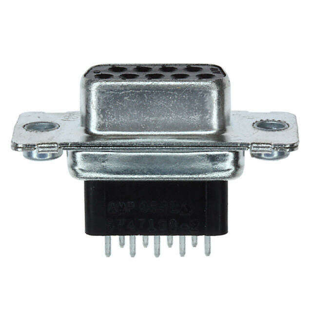
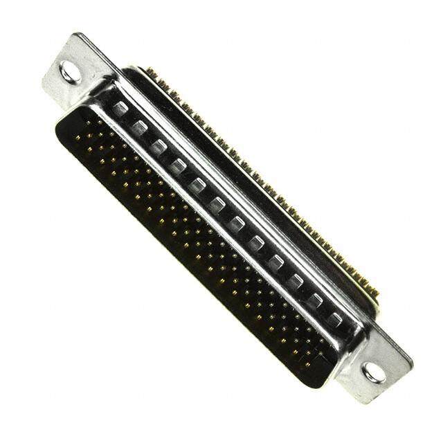
ICGOO电子元器件商城为您提供L77HDA26S由Amphenol设计生产,在icgoo商城现货销售,并且可以通过原厂、代理商等渠道进行代购。 L77HDA26S价格参考¥10.05-¥17.38。AmphenolL77HDA26S封装/规格:D-Sub 连接器, 26 位 D-Sub,高密度 插座,母形插口 连接器。您可以下载L77HDA26S参考资料、Datasheet数据手册功能说明书,资料中有L77HDA26S 详细功能的应用电路图电压和使用方法及教程。
| 参数 | 数值 |
| 产品目录 | |
| 描述 | DSUB HD 26SCKT SLDR CUPD-Sub高密度连接器 D-SUB HIGH DENSITY |
| 产品分类 | |
| 品牌 | Amphenol Commercial Products |
| 产品手册 | |
| 产品图片 | |
| rohs | 符合RoHS无铅 / 符合限制有害物质指令(RoHS)规范要求 |
| 产品系列 | D-Sub高密度连接器,Amphenol Commercial Products L77HDA26S* |
| 数据手册 | |
| 产品型号 | L77HDA26S |
| 产品种类 | D-Sub高密度连接器 |
| 位置数量 | 26 |
| 商标 | Amphenol Commercial Products |
| 型式 | Female |
| 外壳大小 | E |
| 外壳材质 | Steel |
| 外壳电镀 | Tin |
| 安装角 | Straight |
| 安装风格 | Panel |
| 工厂包装数量 | 90 |
| 排数 | 3 |
| 标准包装 | 100 |
| 电流额定值 | 3 A |
| 端接类型 | Solder |
| 触点材料 | Bronze |


- 商务部:美国ITC正式对集成电路等产品启动337调查
- 曝三星4nm工艺存在良率问题 高通将骁龙8 Gen1或转产台积电
- 太阳诱电将投资9.5亿元在常州建新厂生产MLCC 预计2023年完工
- 英特尔发布欧洲新工厂建设计划 深化IDM 2.0 战略
- 台积电先进制程称霸业界 有大客户加持明年业绩稳了
- 达到5530亿美元!SIA预计今年全球半导体销售额将创下新高
- 英特尔拟将自动驾驶子公司Mobileye上市 估值或超500亿美元
- 三星加码芯片和SET,合并消费电子和移动部门,撤换高东真等 CEO
- 三星电子宣布重大人事变动 还合并消费电子和移动部门
- 海关总署:前11个月进口集成电路产品价值2.52万亿元 增长14.8%


PDF Datasheet 数据手册内容提取
D -S C UBMINIATURE ONNECTORS DIN 41612 FCC Filtered Circuit Board Connectors Connectors RJ Modular Jacks IDC Miniature Connectors Ribbon Connectors 20 Melford Drive Scarborough, Ontario ACCESSORIES STANDARD DENSITY SURFACE MOUNT RECEPTACLES HIGH DENSITY Canada M1B 2X6 © Amphenol Canada Corp. Specifications subject to change without notice. Telephone: (416) 754-5656 Designed by K Jasper Marketing Communications Inc. Facsimile: (416) 754-8668 Email: sales@amphenolcanada.com Website: www.amphenolcanada.com
GENERAL DESCRIPTION: Amphenol’s line of D-Subminiature rack and panel connectors is part of an industry standard for applications requiring reliable, rugged, connectors. These connectors are designed to accommodate rack and panel, cable to panel and cable to cable applications. D-Subminiature connectors are pin and socket devices that employ contacts encased in a molded dielectric insert surrounded by a "D"shaped shell for polarization. MARKETS: Amphenol D-Subminiature connectors can be used in commercial, industrial or military markets. We offer a broad selection of dielectric materials and contact styles and configurations to meet all of your design requirements. APPLICATIONS INCLUDE: • Business equipment • Electronic office systems • Data communications • Medical equipment • Mobile communications • Consumer electronics AMPHENOL D-SUB FEATURES: • Industry standard interfacing RS232 and RS449 mating configurations per EIA standards. • UL Component Recognition File number E64911 (617, 841, 17, 17D, 17HD, ED, 17RR, 17SD, 117DF, 17BH, 17TW • Variations available: Solder cup Straight pc mount solder Right angle pc mount solder Solderless wire wrap Crimp High Density Right Angle High Density Straight Stacked Right Angle PC mount Surface mount • Five shell sizes offer widest choice of contact positions: 9, 15, 25, 37 and 50 in standard density and 15, 26, 44, 62 and 78 positions in high-density. • Inserts are flame-retardant thermoplastic. • Accessories for all applications are available including strain reliefs, cable clamps, shielded backshells, mating hardware and connector to pc board mounting hardware. • Automatic and manual tooling is available for both crimp and IDC versions. • Contact Amphenol for lease information. Dimensions and characteristics are subject to change without notice.
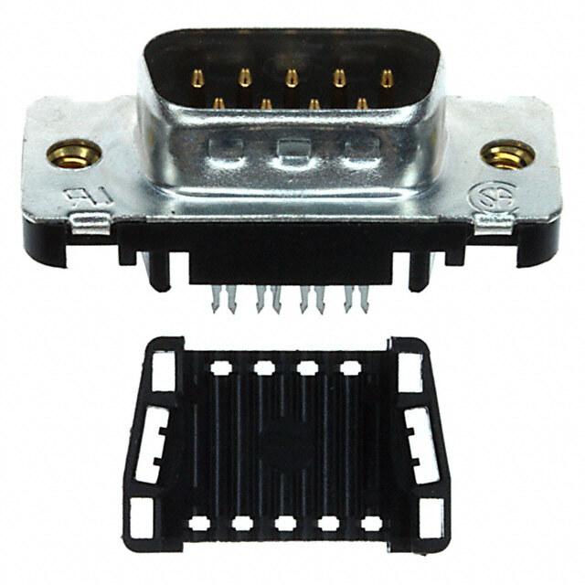
High Density 17E BH/HD SERIES SPECIFICATIONS: MATERIALS AND PLATINGS Shells Steel, tin plated, grounding indents on plug. Contact Material Copper alloy Contact Plating Engagement area: gold (see ordering information). Termination End 150µ"(3.81µm) tin/lead Nickel Underplate 50µ"(1.27µm) entire contact Amphenol’s High Density D-Subminiature connectors ELECTRICAL DATA compleme nt Amphenol’s extensive D-Subminiature connector line. Current Rating 3 Amps maximum per contact Voltage Rating 125 VAC This line of connectors offers many Dielectric Withstanding Voltage 1000 VAC (minimum) superior features, high performance Dielectric Glass filled thermoplastic, black, UL 94 VO level and low installation cost. Insulation Resistance 5,000 Megaohms (minimum) Contact Resistance 15 Milliohms (maximum) The connector configurations are available in 15, 26, 44, 62 CLIMATIC DATA and 78 positions. Operating Temperature -67°F (-55°C) to 221°F (105°C) The product offering includes PCB mount connectors in both straight or right angle termination styles. Straight PCB mount are available in both Fixed Screw Machine and Stamped and Formed contacts, while Right Angle PCB mount are only available with Stamped and Formed contacts. A cable mount version with solder terminations is also available, which can be combined with Amphenol’s standard line of shielded or unshielded backshells. • Industrial • Telecom • Any industry standard INCHES (MM) I / O connections 2 TELEPHONE: (416) 754-5656 FAX: (416) 754-8668 E-MAIL: SALES@AMPHENOLCANADA.COM
17E BH/HD SERIES High Density / Right Angle, PC Mount Front Metal Shell, .350 (8.89) Footprint / Fixed Contact DIMENSIONS FOR 15 - 62 POSITION (3 ROW)(SHOWN WITH FIXED FEMALE SCREWLOCKS) DIMENSIONS FOR THE 78 POSITION (4 ROW) ORDERING INFORMATION 17EBH Series High Density D-Sub Front Metal Shell, Right-Angle PC Mount 17EBH 0XX - X - XX - X - XX Series PCB Mount Options 00 Clear hole Number Of Positions 10 Arrowhead Board 15, 26, 44, 62, 78 Panel Mounting Options Type 0 .120 (3.05) Clear Hole P Pin (male) 1 #4-40 Threaded Hole S Socket (female) 2 #4-40 Fixed Female Screw Plating Code AA Gold Flash over Nickel AM 30µ"(.76µm) Gold over Nickel TELEPHONE: (416) 754-5656 FAX: (416) 754-8668 E-MAIL: SALES@AMPHENOLCANADA.COM 3
High Density 17EHD SERIES Solder Cup And Straight P.C. Mount / Double Metal Shell Fixed Contact DIMENSIONS Panel Mount Options (standoff) 1 = .190 (5.8) 3 = .124 (3.8) ORDERING INFORMATION 17E HD Series High Density D-Sub Solder Cup & Straight P.C. Mount, Front Metal Shell Fixed Contact 17EHD 0XX - X - XX - X - XX Series Termination Types: 00 Solder Cup Number Of Positions 30 Board-mount, Vertical 15, 26, 44, 62 ,78 32 Board-mount, Vertical with Boardlocks 33 Board-mount, Vertical with standoff, Type no boardlock P Pin (male) S Socket (female) Panel Mounting Options: 0 .120 (3.05) Clear Hole 1 #4-40 Threaded Hole .190 (5.8) 2 #4-40 Fixed Female Screwlock 3 #4-40 Threaded Hole .124 (3.8) Plating Code: AA Gold Flash over Nickel AM 30µ" (.76µm) Gold over Nickel INCHES (MM) 4 TELEPHONE: (416) 754-5656 FAX: (416) 754-8668 E-MAIL: SALES@AMPHENOLCANADA.COM
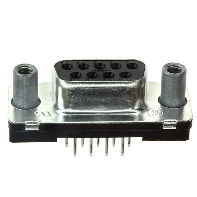
Right-Angle Board Mount Connectors 6E17 SERIES Front Metal Shell SPECIFICATIONS: MATERIALS AND PLATINGS Shells Steel, tin plated Contacts Precision formed copper alloy Contact Plating Gold over nickel Contact Forces Engagement: 12 oz. max. (340.2 g) Separation: .75 oz. min. (21.26 g) ELECTRICAL DATA Current Rating 5 amps Dielectric Withstanding Voltage 1000 VAC/60 sec. Dielectric Glass filled thermoplastic, black, UL 94 VO Contact Resistance 15 milliohms max. Amphenol's 6E17 series of right angle CLIMATIC DATA commercial connectors provide high Temperature Range -67°F (-55°C) to 221°F (105°C) performance at competitive prices. The front metal shell helps to provide reduced EMI/ RFI emissions, and the contacts are selectively plated to provide additional high performance. The 6E17 series are available in a variety of board mounting and grounding options including arrowhead boardlocks and #4-40 threaded inserts. Front mounting holes are also available threaded, un-threaded and with installed female hex screwlocks. • Industrial • Telecom • Any industry standard I / O connections INCHES (MM) 8 TELEPHONE: (416) 754-5656 FAX: (416) 754-8668 E-MAIL: SALES@AMPHENOLCANADA.COM
6E17 SERIES Right-Angle Board Mount Connectors Front Metal Shell DIMENSIONS ORDERING INFORMATION 6E17 X - 0XX - X - XX - X - XX - X Series Variation Code E for U & Y Footprint Number of Contacts 09, 15, 25, 37 Contact Housing Characteristics 20 Tin plated receptacle 21 Tin plated plug with grounding indents .318 .590 Description of PC (8.08) (14.99) Board Mounting Style Code Panel Mounting Options FootprintFootprint Characteristics 0 .120 (3.05) clear hole A .120 (3.05) diameter mtg hole A 1 #4-40 threaded hole with wrap-around ground strap 2 #4-40 threaded hole with female screwlock C spit arrowhead boardlock B 4 Fixed female round screwlock D U .120 (3.05) diameter mtg hole C&E J #4-40 threaded mtg hole D Code Contact Plating Y split arrowhead boardlock F BF Engagement area 3µ"(.076µm) gold flash, terminal end area 100µ"/200µ(2.54µm/5.08µm) Code Contact Type tin/lead underplate of 50µ"(1.27µm) nickel P Pin (male) CF Engagement area 15µ"(.381µm) gold flash, S Socket (female) terminal end area 100µ"/200µ(2.54µm/5.08µm) tin/lead underplate of 50µ"(1.27µm) nickel AJ Engagement area 30µ"(.76µm) gold, terminal end area 100µ"/200µ(2.54µm/5.08µm) For filtered version, see page 56. tin/lead underplate of 50µ"(1.27µm) nickel TELEPHONE: (416) 754-5656 FAX: (416) 754-8668 E-MAIL: SALES@AMPHENOLCANADA.COM 9
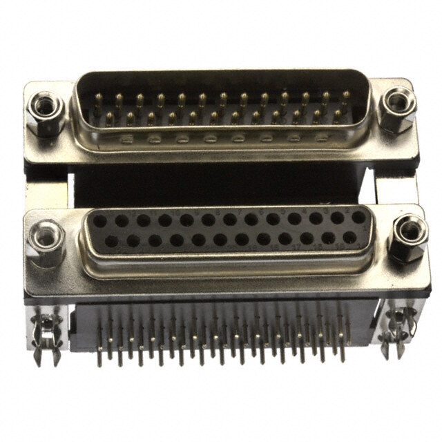
Dual Port Connectors 6E17 H SERIES SPECIFICATIONS: MATERIALS AND PLATINGS Shells Steel, tin plated Contacts Precision formed copper alloy Contact Plating Gold over nickel Contact Forces Engagement: 12 oz. max. (340.2 g) Separation: .75 oz. min. (21.26 g) ELECTRICAL DATA Amphenol's 61E7 series dual port Current Rating 5 amps connectors are a state of the art Dielectric Withstanding Voltage 1000 VAC/60 sec. design. The front metal shell helps Dielectric Glass filled thermoplastic, black, UL 94 VO reduce EMI/RFI emissions. Contact Resistance 15 milliohms max. Contacts are selectively plated for CLIMATIC DATA high performance at a low cost. Temperature Range -67°F (-55°C) to 221°F (105°C) Designed to save PC board space, Amphenol’s dual port “D” provides two input output connectors in a minimal amount of board space. These connectors are available with various stacking options: same gender, mixed gender and multiple pin counts. INCHES (MM) 10 TELEPHONE: (416) 754-5656 FAX: (416) 754-8668 E-MAIL: SALES@AMPHENOLCANADA.COM
6E17 H SERIES Dual Port Connectors DIMENSIONS Product Description Dimensions Code Letter Top Bottom E F Connector Connector A Pin Pin B Socket Socket 0.900 ±0.010 1.415 (22.86 ±0.25) (35.94) C Pin Socket D Socket Pin E Pin Pin F Socket Socket 0.750 ±0.010 1.265 (19.05 ±0.25) (32.13) G Pin Socket H Socket Pin J Pin Pin K Socket Socket 0.625 ±0.010 1.140 (15.88 ±0.25) (28.96) L Pin Socket M Socket Pin ORDERING INFORMATION 6E17H X - XX - X - XX - X - XX - X Series Variation Code 6E17H Dual port; L for .311 (7.89) Footprint right angle solder tail Code Housing Characteristics Code Boardlock 00 Steel shell, tin plated receptacles without C Boardlock option grounding dimples (options B, F, K) O No PC boardlock 01 Steel shells, tin plated plugs with grounding dimples (options A, E, J) Code Number of Contacts 03 Steel shells, tin plated, plug shell with grounding dimples 18 2 x 9 15 15 over blank and receptacle shell without dimples (options C,G,L,D,H,M) 30 2 x 15 34 9 / 25 50 2 x 25 43 25 / 9+9 Code Panel Mounting Options 74 2 x 37 H15A VGA / Triple Audio 0 120"clear hole 40 15 / 25 1 #4-40 threaded hole 2 #4-40 threaded hole with female screwlock Consult factory for other available configurations Code Contact Plating BF Engagement area 3µ"(.076µm) gold flash, 58.064 48.388 40.31 Product Description terminal end area 100µ"/200µ"tin/lead, (2.54µm/5.08µm) (22.86) (19.05) (15.87) Top Bottom tin/lead underplate of 50µ"(1.27µm) nickel Spacing Spacing Spacing Connector Connector CF Engagement area 15µ"(.381µm) gold flash, A E J Pin Pin terminal end area 100µ"/200µ"(2.54µm/5.08µm) B F K Socket Socket tin/lead underplate of 50µ"(1.27µm) nickel C G L Pin Socket AJ Engagement area 30µ"(.76µm) gold, terminal end area D H M Socket Pin 100µ"/200µ(2.54µm/5.08µm) tin/lead underplate For filtered version, see page 55. of 50µ"(1.27µm) nickel TELEPHONE: (416) 754-5656 FAX: (416) 754-8668 E-MAIL: SALES@AMPHENOLCANADA.COM 11
High Temperature 6E17S SERIES Straight Board Mount Connectors SPECIFICATIONS: MATERIALS AND PLATINGS Shells Steel/nickel plated Contacts Precision formed copper alloy Contact Plating Gold over nickel ELECTRICAL DATA Current Rating 5 amps Voltage Rating 600 V Dielectric Glass filled thermoplastic, black, UL 94 VO Contact Resistance 10 milliohms (max.) Amphenol’s high temperature, low profile D-Sub connector gives CLIMATIC DATA you a high quality, reliable commercial connector to meet Temperature Range Environmental: -67°F (-55°C) to 302°F (150°C) today’s market demands. Process Compatibility IR-Air Convection 500°F (260°C) for 20 seconds INCHES (MM) 14 14 TELTEPEHLEOPNHEO: N(E4:1 (64)1 765) 47-5546-5566 5F6AX :F A(4X1: 6(4) 1765)4 7-85646-886 E6-8M AEIL-:M SAAILLE: SS@ALAEMS@PHAEMNPOHLECNAONLACDAAN.CAODMA.COM
6E17S SERIES High Temperature Straight Board Mount Connectors DIMENSIONS ORDERING INFORMATION 6E17S C - 0XX - X - XX - X - XX Series Code Housing Characteristics 20 Tin plated receptacle Code Boardlock 21 Tin plated C Split arrowhead boardlock O No boardlock Code Panel Mounting Options 1 #4-40 threaded hole Number of contacts 2 #4-40 threaded hole with 9, 15, 25 or 37 female screwlock 3 M-3 threaded hole Code Gender P Pin (male) S Socket (female) Code Contact Plating BJ Engagement area 10µ"(2.54µ) gold, terminal end area 100µ"/200µ"(2.54µ/5.08µ) -tin/lead, underplate of 50µ"(1.27µ) nickel AJ Engagement area 30µ"(.76µ) gold, terminal end area 100µ"/200µ"(2.54µ/5.08µ) -tin/lead, underplate of 50µ"(1.27µ) nickel TELEPHONE: (416) 754-5656 FAX: (416) 754-8668 E-MAIL: SALES@AMPHENOLCANADA.COM 15
ED-EHD D-Sub connectors - Screw-machined contacts STANDARD AND HIGH DENSITY WATERPROOF CONNECTORS S N The 17ED and 17EHD series are C Materials and Platings O I I suitable for waterproof applications. T T S Shells Steel 2.5µm(100µ”) min tin over 1.25µm(50µ”) min nickel P I I R Body Glass-filled thermoplastic R The machined contacts provide E C T Flame retardant to UL94 V-0 Color Black S robustness and reliability. C E A D R Contacts Copper alloy(Brass for plug, Phospher bronze for socket) A This series offers: H gold over 1.25µm(50µ”) min nickel C - Panel mount connectors with Boardlock Copper alloy, 100µ” min. sn over 50µ” min. nickel. solder cup, straight and right Standoff Copper alloy, 100µ” min. sn over 50µ” min. nickel. angle PCB terminations. Electrical Data Connectors are waterproof unmated. Current rating 5.0A Voltage rating 300V rms at 50Hz Insulation resistance >5000MΩ HHaarrsshh eennvviirroonnmmeenntt Contact resistance 20mΩ Max. ccoonnnneeccttoorrss Climatic Data Operating temperature -55°C to +85°C Salt spray 48 hours Waterproof rating IP 67 minimum Mechanical Data Mating and unmating force S • Marine electronic devices Unit: kg (lb) N O I • Industrial electrical T No. of Cts ED EHD A • Security Monitoring C ED EHD Mate (max) Unmate (min) Mate (max) Unmate (min) LI • Robotics P 9 15 3.05 (6.74) 0.36 (0.79) 3.81 (8.42) 0.52 (1.14) P • Lighting systems A D 15 26 5.09 (11.24) 0.46 (1.01) 5.95 (13.16) 1.05 (2.32) H E 25 44 8.44 (18.66) 0.81 (1.80) 9.26 (20.46) 1.37 (3.02) - D Mating cycles Gold flash : 100 cycles E 0.76µm (30µ”) : 500 cycles
Termination A T A D Solder cup (blank) : L A C I 6.5 (0.256) 8.2 (0.323) N H C 5.8 (0.228) E T Standard density High density Straight PCB with standoff and boardlocks: 8.2 (.323) 7.9 (.311) 4.0 (.157) 4.0 (.157) 4) 4) 2 2 0 0 6(. 6(. 0. 0. ø ø Standard density High density Right angle PCB with brackets and boardlocks: 10.9 (0.429) 10.9 (0.429) 6.7 (0.263) 8) 5.58 (0.219) 3.5 (0.138) 2.84 (0.112) 13 ø0.6(.024) 0. 2.54 (0.100) ø0.6(.024) 5 ( 2.54 (0.100) 3. Standard density High density D Right angle PCB without brackets and boardlocks: H E - D E 10.9 (0.429) 10.9 (0.429) 6.7 (0.263) 38) 5.58 (0.219) 3.5 (0.138) 1 2.84 (0.112) 5 (0. 2.54 (0.100) ø0.6(.024) ø0.6(.024) 3. 2.54 (0.100) Standard density High density
S Shell Size Dimensions N O I S N E M I D L L A R A E F / F’ V B O B’ E D D’ C 3.85 SHELL Contact A B B’ C D D’ E F F’ SIZE P: pin ±0.25 0 / -0.20 +0.20 / 0 ±0.10 0 / -0.25 +0.25 / 0 ±0.25 +0.10/-0.20 ±0.10 S: socket (±.010) (0/-.008 (+.008/0) (±.004) (0/-.010) (+.010/0) (±.010) (+.004/-.008) (±.004) P 39.4 16.8(0.661) 25.0 8.2(0.325) 21.0 5.9(0.232) E S (1.551) 16.4(0.646) (0.984) 8.0(0.315) (0.827) 6.2(0.244) P 47.7 25.1(0.988) 33.3 8.2(0.325) 21.0 5.9(0.232) A S (1.878) 24.8(0.976) (1.311) 8.0(0.315) (0.827) 6.2(0.244) P 64.5 28.8(1.528) 47.0 8.2(0.325) 21.0 5.9(0.232) B S (2.539) 38.5(1.513) (1.850) 8.0(0.315) (0.827) 6.2(0.244) Panel cutouts PANEL THICKNESS 2.0 Max 0 1 0 ±0. 0.1 A 11 3 ± B R1.5 R1.5 SHELL A B SIZE ±0.10(±.004) 0 / -0.10(0 / -.004) E 28.8 (1.111) 20.0 (0.788) A 36.5 (1.438) 28.0 (1.103) B 51.0 (2.009) 41.5 (1.635)
S Connector Dimensions E T O N 2 5mm 4 3 6mm 1 5 NO Description Material Qty 2 Housing Black thermoplastic UL 94-VO 1 g. n 1 Front shell Steel tin plated 1 writi n 3 Ring Silicone 1 d i e ov 4 #4-40 Front screw lock Brass tin plated 2 ppr a 5 #4-40 Front screw lock Brass tin plated 2 nless u d, e bit hi o pr How to order on is ati L17 ED ... ... ... ... plic u d ny A ary. contact plating: ess ec 0 : gold flash m n L17ED: standard density series 1 : 0.38µm gold (15µ”) ee d L17EHD: high densty series 2 : 0.76µm gold (30µ”) we ay w ny a NStuamndbaerrd o dfe cnosnityta: c9t,s 15, 25 T0e :r Smoilndaetri ocnup: ducts in o High density: 15, 26, 44 1 : Straight PCB without ur pr stand-off or boarlocks dify o 2 : Straight PCB with stand-off mo Contact type: and boarlocks ht to P : Pin 3 : Right angle PCB without e rig S : Socket brackets or boarlocks e th 4 : Right angle PCB with erv es brackets and boarlocks We r nly. o For special request, please consult factory ne eli d ui g a as e ar nt Do not hesitate to contact us for further information me u oc d Amphenol IT & Communication Products his Block A3/A4, The 4th Industrial District of n in t Industrial Headquarters, Dong Keng Road give Gong Ming Town, Shen Zhen China n o Fax:+86(0)755 2754 9955 mati Technical Support nfor InfToe-dl:+su8b6@(0)a7m55p h2e7n1o7l. c7o9m45.cn e i/BD/E http://www.dsubconnector.com EH D- E
TW Hybrid D’Sub series T Specifications N Amphenol D’Sub TW Hybrid Series permits N O E • Connectors according to: MIL C24308 - NFC93425 - HE507 I a mix of contacts including signal, power, T T N P shielded, high voltage and fiber optics in the O I C R same housing with 18 different contacts Materials and platings Electrical Data C S arrangements. Shells Steel-Tin plating Current rating E Insulators High temperature black thermoplastic Signal contacts 7.5 A. with 10 A. peaks D This economic series was fist developed from Signal contacts Female: machined bronze Power contacts our military series, and has improved features: Material Male: machined brass PCB terminations 10 to 40 A. - new contacts Solder cup terminations 10 to 40 A. Plating finish 16µ “Au over 79µ” Ni min. Crimp terminations 10 to 40 A. - new high temperature black thermoplastic insert Or 30µ” Au over 79µ” Ni min. Shielded contacts 0.5 A. Shielded contacts Female: machined bronze - PCB configurations come preloaded with Voltage rating Material Male: machined brass fixed contacts and brackets. Signal and power contacts 300 V.R.M.S. at 50 Hz Plating Shielded contacts 150 V.R.M.S. at 50 Hz These connectors are supplied with screw Inner conductor 16µ “Au or 30µm Au over 79µ” Ni Shielded contacts machined contacts which are fixed in the insulator. Outer ring 10µ “Au over 79µ” Ni Frequency range 0-1 GHz Terminations Tinned Acomplete range of housings are also Attenuation 0.2dB Except solder cup and crimp terminations gold flash V. S. W. R. 1.4(+0.04/GHz) available for cable application. Power contacts Female: machined bronze Characteristic impedance 50 Ohms Material Male: machined brass AA ffuullll rraannggee ooff Dielectric withstanding Plating voltage ≥ 1000 V.R.M.S. at 50Hz Contacts 16µ “Au or 30µ” Au over 79µ” Ni Terminations Tinned Insulation resistance ≥ 5000 M Ohms at 500 VDC aarrrraannggeemmeennttss Except solder cup and crimp terminations gold flash Contact resistance ≤ 5m Ohms Brackets Steel-Tin plating Shell resistance ≤ 1m Ohm ccoommppaattiibbllee wwiitthh (electrical grounding) Front jackscrews Brass-Tin plating Rear clinch nuts Brass-Tin plating Boardlocks Bronze-Tin plating rreeffllooww pprroocceessss Stand-off Brass-Tin plating Climatic Data Mechanical data S • Commercial N O Operating temperature -55˚C + 155˚C Shells With or without dimples I • Medical (with peaks up to 180˚C) Contact retention force in dielectric material > 40N AT • Industrial Damp heat 56 days (40˚C - 95% HR) C Maximum mating and unmating force I Salt spray 48 hours With dimples E size = 70 N L • Telecom P A size = 80 N P • Any application requiring B size = 100 N A 1 optimization of space E C size = 150 N D size = 180 N / Without dimples E size = 30 N W A size = 50 N T B size = 80 N C size = 120 N D size = 160 N Compatible with process IR - Air convectioned 260˚ for 20 s. Resistance to solder iron heat 260˚C for 30 s. Mating cycles ≥ 200 (classe ll) or 500 (classe l) Blind mating system Available upon request Polarization Available with locking accessories Consult factory
A Shell and contacts plating T A D L A C CLASS ll CLASS l I N 0.4µm (16µ”) Au contacts gold plating 0.76µm (30µ”) Au contacts gold plating H 200 mating cycles 500 mating cycles C E T Types Shells and plating Types Shells and plating Tin plated shell Tin plated shell 77 TW 177 TW *Male and female *Male and female 717 TW Tin plated shell with dimples 777 TW Tin plated shell with dimples Male only Male only Housing arrangements Male front view Arrangement ...... 5W1 7W2 11W1 Shell size ............ E A A Arrangement ...... 3W3 5W5 9W4 Shell size ............ A B B Arrangement ...... 13W3 17W2 21W1 Shell size ............ B B B Arrangement ...... 27W2 13W6 17W5 Shell size ............ C C C Arrangement ...... 21W4 8W8 25W3 Shell size ............ C C C Arrangement ...... 24W7 36W4 43W2 Shell size ............ D D D 2
Shell size dimensions A T A D L A 1.5 F A C H 10˚ 0.9 B NI B’ H C E J D’D E T ø 3.1 G G Shell Contact A B B‘ C D D‘ E F F‘ G G‘ H J size P: Pin ±0.25 0/-0.20 +0.20/0 ±0.10 0/-0.25 +0.25/0 ±0.20 +0.05/-0.20 +0.10/-0.20 +0.10/-0.20 ±0.10 +0.10/-0.40 0/-0.50 S: Socket (±.010) (0/-.008) (+.008/0) (±.004) (0/-.010) (+.010/0) (±.008) (+.002/-.008)(+.004/-.008)(+.004/-.008) (±.004) (+.004/-.016) (0/-.020) 16.8 8.2 10.9 5.9 P 30.7 (.661”) 25.0 (.323”) 12.4 (.429”) (.232”) 19.4 11.0 E (1.209”) 16.4 (.984”) 8.0 (.488”) 11.1 6.2 (.764”) (.433”) S (.646”) (.315”) (.437) (.244”) 25.1 8.2 10.9 5.9 P 39.0 (.988”) 33.3 (.323”) 12.4 (.429”) (.232”) 27.7 11.0 A (1.535”) 24.8 (1.311”) 8.0 (.488”) 11.1 6.2 (1.091”) (.433”) S (.976”) (.315”) (.437) (.244”) 38.8 8.2 11.0 5.8 P 52.9 (1.528”) 47.0 (.323”) 12.4 (.433”) (.228”) 41.4 11.0 B (2.083”) 38.5 (1.850”) 8.0 (.488”) 11.1 6.2 (1.630”) (.433”) S (1.513”) (.315”) (.437) (.244”) 55.3 8.2 11.0 5.8 P 69.2 (2.177”) 63.5 (.323”) 12.4 (.433”) (.228”) 57.9 11.0 C (2.724”) 54.9 (2.500”) 8.0 (.488”) 11.1 6.2 (2.280”) (.433”) S (2.161”) (.315”) (.437) (.244”) 52.7 11.0 11.0 5.8 P 66.8 (2.075”) 61.1 (.433”) 15.2 (.433”) (.228”) 55.5 13.8 D (2.630”) 52.5 (2.406”) 10.9 (.598”) 11.1 6.2 (2.185”) (.543”) S (2.067”) (.429”) (.437) (.244”) Panel cutouts Optimal cutout for rear mounting Standard cutout A A B B 10˚ 10˚ øG G H F E D R D Rd Rading J Rd Rading J C C Shell Mounting A B C D E F G H J size method ±0.20 ±0.20 ±0.20 ±0.20 ±0.20 ±0.20 ±0.20 ±0.20 ±0.20 (±.008) (±.008) (±.008) (±.008) (±.008) (±.008) (±.008) (±.008) (±.008) 22.2 11.1 13.0 6.5 2.1 Front (.874”) (.437”) 25.0 12.5 (.512”) (.256”) 3.0 1.5 (.083”) E 20.5 10.2 (.984”) (.492”) 11.4 5.7 (.118”) (.059”) 3.4 Rear (.807”) (.402”) (.449”) (.224”) (.0134”) 30.5 15.3 13.0 6.5 2.1 1 Front (1.201”) (.602”) 33.3 16.7 (.512”) (.256”) 3.0 1.5 (.083”) E A 28.8 14.4 (1.311”) (.657”) 11.4 5.7 (.118”) (.059”) 3.4 / Rear (1.134”) (.567”) (.449”) (.224”) (.0134”) W 44.3 22.1 13.0 6.5 2.1 T Front (1.744”) (.870”) 47.0 23.5 (.512”) (.256”) 3.0 1.5 (.083”) B 42.5 21.3 (1.850”) (.925”) 11.4 5.7 (.118”) (.059”) 3.4 Rear (1.673”) (.839”) (.449”) (.224”) (.0134”) 60.7 30.4 13.0 6.5 2.1 3 Front (2.390”) (1.197”) 63.5 31.7 (.512”) (.256”) 3.0 1.5 (.083”) C 59.1 29.5 (2.500”) (1.248”) 11.4 5.7 (.118”) (.059”) 3.4 Rear (2.327”) (1.161”) (.449”) (.224”) (.0134”) 58.3 29.2 15.8 7.9 2.1 Front (2.295”) (1.150”) 61.1 30.6 (.622”) (.311”) 3.0 1.5 (.083”) D 56.3 28.2 (2.406”) (1.205”) 14.1 7.1 (.118”) (.059”) 3.4 Rear (2.217”) (1.110”) (.555”) (.280”) (.0134”)
A Straight connector footprint T A D L A 1 A 2 A 3 A C I N H C E T B B B Signal tail 0.6 mm Dia. (.0236”) 1.6 mm (.063”)PCB For other PCB thickness: consult factory. Dimensions Description a b 4.80 mm 7.2 mm Power (.126” tail dia.) 1 (.198”) (.283”) 4.80 mm 7.2 mm Power (.0787” tail dia.) 1 (.198”) (.283”) 4.00 mm 7.2 mm Shielded 3 (.157”) (.283”) 5.00 mm 11.50 mm Signal 2 (.196”) (.453”) Straight contact combinations Arrangement with signal contacts Arrangement without signal contacts 3W3 - 5W5 - 8W8 See above dimensions Size 8 and 20 Contacts See above dimensions Size 8 Contacts Power 3.2 mm DIA. (.126”) Power only P 3SY (20 to 40 A) and signal P 3Y 3.2 mm DIA. (.126”) (20 to 40 A) Power 2 mm DIA. (.0787”) P 2SY (10 to 20 A) and signal Power only P 2Y 2 mm DIA. (.0787”) (10 to 20 A) CSY Shielded and signal 4 SY Signal only CY Shielded only Signal (Size 20) No reference with solder cup terminations Housing preloaded with contacts
Right angle connector footprint A T A D L 1 2 3 A C I N H B B B C C C C E T A A A Signal tail 0.6 mm Dia. (.0236”) Europe Mix MIL 1.6 mm (.063”) PCB HE 5 pattern = Mixed pattern = MIL pattern = For other PCB thickness: consult factory. - Europ. height - MIL height - MIL height - Europ. footprint - Europ. footprint - MIL footprint pitch between pitch between pitch between 2 rows: .100” 2 rows: .100” 2 rows: .112” Description a b c a b c a b c 10.30mm 6.30mm 10.00mm 10.30mm 6.30mm 10.00mm Shielded 1 - - - (.406”) (.248”) (.394”) (.406”) (.248”) (.394”) 10.30mm 7.20mm 11.20mm10.30mm 6.30mm 9.50mm 8.10mm 6.30mm 9.50mm Signal 2 (.406”) (.283”) (.441”) (.406”) (.248”) (.374”) (.319”) (.248”) (.374”) 11.57mm 7.20mm 10.50mm11.57mm 6.30mm 9.50mm 9.52mm 6.30mm 9.50mm Power (.0787” tail dia.) 3 (.456”) (.283”) (.413”) (.456”) (.248”) (.374”) (.375”) (.248”) (.374”) 21.46mm 7.20mm 10.50mm21.46mm 6.30mm 9.50mm 21.46mm 6.30mm 9.50mm Power (.126” tail dia.) 3 (.845”) (.283”) (.413”) (.845”) (.248”) (.374”) (.845”) (.248”) (.374”) Note: above dimensions correpond to sizes E to C. Consult factory for D sizes. Connector comes equiped with contacts and brackets. Right angle contacts combinations Arrangement with signal contacts Arrangement without signal contacts 3W3 - 5W5 - 8W8 European Mixed MIL (U.S.) Size 8 and European Mixed MIL (U.S.) Size 8 contacts footprint footprint footprint 20 Contacts footprint footprint footprint only 1 Power 3.2 mm Power only E EP3SV HP3SV MP3SV DIA. (.126”) (20 to EP3V HP3V MP3V 3.2 mm DIA. (.126”) / 40 A) and signal (20 to 40 A) W T Power 2 mm Power only EP2SV HP2SV MP2SV DIA. (.0787”) (10 to EP2V HP2V MP2V 2.0 mm DIA. (.0787”) 20 A) and signal (10 to 20 A) 5 - HCSV MCSV Shielded and signal - HCV MCV Shielded only ESV HSV MSV Signal only
A MMoouunnttiinngg ooppttiioonnss T A D L Right angle version A C Connectors come equiped with metal brackets I N H C BLANK: 3.10mm (.122”) dia mounting hole RM6: metal brackets + boardlock E T Metal bracket RM6 Straight version BLANK: 3.10mm (.122”) dia mounting hole RM54: RM5 4.40 threaded RM53: RM5 M3 threaded 7.2 (.283) max. max.) 1.5 059 (. RM5 RM8 RM84: RM8 4.40 threaded RM83: RM8 M3 threaded A514: blind mating system FM: float mounting system 3.5 ø2.2 (.086) (.137) 3.6 max. (.141 max.) + 0.25 018) 31 ø(. 19.9 2.25088) (.783) ø(. Straight and right angle version 4R: 4.40 rear nut 4F: 4.40 front female screwlock 3R: M3 rear nut 3F: M3 front female screwlock 3.(4.134) 7(..1279) 6
H igh power contacts A T A D L A 4.80189”) 4.80189”) NIC (. (. H C E T 5.20205”) 5.20205”) (. (. Solder cup version 22 22 (.866”) øA øB (.866”) øA øB 16622”) (. P/N Dimensions Current Plug Socket A mm (inch) B mm (inch) L 17DM 53745-8 L 17DM 53744-7 10 to 20 Amp. 1.80 (.071”) 2.55 (.100”) L 17DM 53745-7 L 17DM 53744-6 20 to 30 Amp. 2.80 (.110”) 3.70 (.145”) L 17DM 53745-1 L 17DM 53744-1 30 to 40 Amp. 4.80 (.189”) 5.60 (.220”) Trim dimensions: 7.5 mm (.295”) Crimp version (.82626”) øA øB (.82626”) øA øB 16622”) (. P/N Dimensions Current Plug Socket A mm (inch) B mm (inch) L 17DM 53745-208 L 17DM 53744-207 10 to 20 Amp. 1.80 (.071”) 2.55 (.100”) L 17DM 53745-207 L 17DM 53744-206 20 to 30 Amp. 2.80 (.110”) 3.70 (.145”) L 17DM 53745-201 L 17DM 53744-201 30 to 40 Amp. 4.80 (.189”) 5.60 (.220”) Trim dimensions: 7.5 mm (.295”) 1 E Crimping tool for all sizes Extraction tool for sizes 8 cts / L17D479SP W T 7
A SSttrraaiigghhtt sshhiieellddeedd ccoonnttaaccttss T A D L A Crimp ferrule and inner solder C I N A H C E T B øD B øD E G F Type P/N Dimensions (inch) Cable - RG Trim dimensions (inch) A Max B D E F G plug L17DM 53740 18.8 (740”) 23.6 (.929”) 1.0 (.039”) 178 B/U 7.9 (.311”) 6.3 (.248”) 2 (.078”) plug L17DM 53740-1 18.8 (740”) 23.6 (.929”) 1.7 (.066”) 179 B/U 316 B/U 7.9 (.311”) 6.3 (.248”) 2 (.078”) plug L17DM 53740-3 21.5 (846”) 23.6 (.929”) 2.8 (.110”) 180 B/U 9.5 (.374”) 7.9 (.311”) 2 (.078”) plug L17DM 53740-5 21.5 (846”) 23.6 (.929”) 3.2 (.126”) 58 C/U 9.5 (.374”) 7.9 (.311”) 2 (.078”) socket L17DM 53742 18.8 (740”) 23.6 (.929”) 1.0 (.039”) 178 B/U 7.9 (.311”) 6.3 (.248”) 2 (.078”) socket L17DM 53742-1 18.8 (740”) 23.6 (.929”) 1.7 (.066”) 179 B/U 316 B/U 7.9 (.311”) 6.3 (.248”) 2 (.078”) socket L17DM 53742-3 21.5 (846”) 23.6 (.929”) 2.8 (.110”) 180 B/U 9.5 (.374”) 7.9 (.311”) 2 (.078”) socket L17DM 53742-5 21.5 (846”) 23.6 (.929”) 3.2 (.126”) 58 C/U 9.5 (.374”) 7.9 (.311”) 2 (.078”) Ferrule and inner solder A B øD B øD E G F Type P/N Dimensions (inch) Cable - RG Trim dimensions (inch) A Max B D E F G short plug L17DM 53740-5000 17.0 (669”) 21.8 (.858”) 1.0 (.039”) 178 B/U 7.9 (.311”) 6.3 (.248”) 2 (.078”) plug L17DM 53740-5001 18.8 (740”) 23.6 (.929”) 1.7 (.066”)179 B/U 316 B/U 7.9 (.311”) 6.3 (.248”) 2 (.078”) plug L17DM 53740-5002 21.5 (846”) 26.3 (1.035”) 2.8 (.110”) 180 B/U 9.5 (.374”) 7.9 (.311”) 2 (.078”) plug L17DM 53740-5005 21.5 (846”) 26.3 (1.035”) 3.2 (.126”) 58 C/U 9.5 (.374”) 7.9 (.311”) 2 (.078”) plug L17DM 53740-5008 18.8 (740”) 23.6 (.929”) 1.0 (.039”) 178 B/U 7.9 (.311”) 6.3 (.248”) 2 (.078”) short socket L17DM 53742-5000 17.0 (669”) 21.8 (.858”) 1.0 (.039”) 178 B/U 7.9 (.311”) 6.3 (.248”) 2 (.078”) socket L17DM 53742-5001 18.8 (740”) 23.6 (.929”) 1.7 (.066”)179 B/U 316 B/U 7.9 (.311”) 6.3 (.248”) 2 (.078”) socket L17DM 53742-5002 21.5 (846”) 26.3 (1.035”) 2.8 (.110”) 180 B/U 9.5 (.374”) 7.9 (.311”) 2 (.078”) socket L17DM 53742-5004 21.5 (846”) 26.3 (1.035”) 3.2 (.126”) 58 C/U 9.5 (.374”) 7.9 (.311”) 2 (.078”) socket L17DM 53742-5006018.8 (740”) 23.6 (.929”) 1.0 (.039”) 178 B/U 7.9 (.311”) 6.3 (.248”) 2 (.078”) 8
R ight angled shielded contact A T A D Crimp ferrule and inner solder L A C I N H C E A T E G F A Type P/N Dimensions (inch) Cable - RG Trim dimensions (inch) A Max B D E F G plug L17DM 53741 13.5 (.531”) 18.6 (.732”) 1.0 (.039”) 178 B/U 9.5 (.374”) 5.9 (.232”) 1.6 (.062”) plug L17DM 53741-1 13.5 (.531”) 18.6 (.732”) 1.7 (.066”) 179 B/U 316 B/U 9.5 (.374”) 5.9 (.232”) 1.6 (.062”) plug L17DM 53741-3 13.5 (.531”) 18.6 (.732”) 2.8 (.110”) 180 B/U 10.7 (.421”) 7.9 (.311”) 2.4 (.094”) plug L17DM 53741-4 13.5 (.531”) 18.6 (.732”) 3.2 (.126”) 58 C/U 10.7 (.421”) 7.9 (.311”) 2.4 (.094”) socket L17DM 53743-2 13.5 (.531”) 18.6 (.732”) 1.0 (.039”) 178 B/U 9.5 (.374”) 5.9 (.232”) 1.6 (.062”) socket L17DM 53743-3 13.5 (.531”) 18.6 (.732”) 1.7 (.066”) 179 B/U 316 B/U 9.5 (.374”) 5.9 (.232”) 1.6 (.062”) socket L17DM 53743-5 13.5 (.531”) 18.6 (.732”) 2.8 (.110”) 180 B/U 10.7 (.421”) 7.9 (.311”) 2.4 (.094”) socket L17DM 53743-6 13.5 (.531”) 18.6 (.732”) 3.2 (.126”) 58 C/U 10.7 (.421”) 7.9 (.311”) 2.4 (.094”) Ferrule and inner solder B B C E G C F øD øD Type P/N Dimensions (inch) Trim dimensions (inch) A Max B D Cable - RG E F G plug L17DM 53741-5000 13.5 (.531”) 18.6 (.732”) 1.0 (.039”) 178 B/U 9.5 (.374”) 5.9 (.232”) 1.6 (.062”) plug L17DM 53741-5001 13.5 (.531”) 18.6 (.732”) 1.7 (.066”) 179 B/U 316 B/U 9.5 (.374”) 5.9 (.232”) 1.6 (.062”) plug L17DM 53741-5003 13.5 (.531”) 18.6 (.732”) 2.8 (.110”) 180 B/U 10.7 (.421”) 7.9 (.311”) 2.4 (.094”) plug L17DM 53741-5004 13.5 (.531”) 18.6 (.732”) 3.2 (.126”) 58 C/U 10.7 (.421”) 7.9 (.311”) 2.4 (.094”) socket L17DM 53743-5000 13.5 (.531”) 18.6 (.732”) 1.0 (.039”) 178 B/U 9.5 (.374”) 5.9 (.232”) 1.6 (.062”) socket L17DM 53743-5001 13.5 (.531”) 18.6 (.732”) 1.7 (.066”) 179 B/U 316 B/U 9.5 (.374”) 5.9 (.232”) 1.6 (.062”) socket L17DM 53743-5003 13.5 (.531”) 18.6 (.732”) 2.8 (.110”) 180 B/U 10.7 (.421”) 7.9 (.311”) 2.4 (.094”) socket L17DM 53743-5004 13.5 (.531”) 18.6 (.732”) 3.2 (.126”) 58 C/U 10.7 (.421”) 7.9 (.311”) 2.4 (.094”) Crimping tool Hand crimp tool 227-0944 (without dies) (M 22 520/5-01) RG cables MIL reference Amphenol P/N dim. between 2 flat surface cavity A cavity B 1 E RG 58 C/U M 22 520/5-05 227 1221-05 5.41 - / RG 178 B/U M 22 520/5-03 227 1221-03 - 2.67 W RG 179 B/U M 22 520/5-03 227 1221-03 3.25 - T RG 180 B/U M 22 520/5-05 227 1221-05 - 4.52 Extraction tool 9 Extraction tool for sizes 8 cts L17D429SP
S Cabling instructions for shielded contacts N O I T C U Straight crimp shielded contacts: inner solder contact R T outer crimp contact S N I soft solder Y outer ring outer ring coaxial shell L B M E S S A braided shield crimp 3.20 inner sleeve Right angle crimp shielded contacts: inner solder contact outer crimp contact inner sleeve coaxial shell outer ring outer ring crimp soft solder soft solder cap into shell after cable 3.20 assembly on 90˚ type coaxes Assembly method - Slide the outer ring over the cable jacket. Trim the cable - Slide the outer ring towards the inner sleeve ans recover according to the recommended dimensions. the braid. - Insert the cable dielectric and the center conductor inside - Using crimp hand tool equipped with the appropriate dies, the inner sleeve. crimp in the area defined. - Solder the central conductor to the shielded center contacts. Solder straight shielded contacts: soft solder outer ring coaxial shell outer ring braided shield solder inner sleeve Solder right angle shielded contacts: coaxial shell inner sleeve outer ring outer ring solder soft solder soft solder cap into shell after cable assembly on 90˚ type coaxes Assembly method - Slide the outer ring over the cable jacket. Trim the cable - Slide the outer ring towards the inner sleeve ans recover according to the recommended dimensions. the braid. - Insert the cable dielectric and the center conductor inside - Solder by introducing metal through the outer ring hole. the inner sleeve. - Solder the central conductor to the shielded center 10 contacts.
How to build your part number R E D R O L ...TW... ... ... ... ... ... O T W O RoHS Compliant H Special Deviations Contacts and Shell Please consult factory Contact Plating Shell Tinned Tinned & Indents; Plug only 0.4µm(16µ”) Au 77 717 Board Mounting Options 0.76µm(30µ”) Au 177 777 For Straight Blank: .120”(3.05mm) Clear Hole Shell size and Configuration: RM53: M3 Threaded (panel side) E5W1, A3W3, A7W2, A11W1, B5W5, B9W4, B13W3, standoff with boarlock B17W2, B21W1, C8W8, C13W6, C17W5, C21WA4 RM54: 4-40UNC Threaded (panel side) C25W3, C27W2, D24W7, D36W4, D43W2 standoff with boardlock RM84: Non-Removable M3 screwlock, w ith standoff and boardlock Gender: P: Pin For Right Angle S: Socket RM6: Metal bracket with boardlocks Contacts: Panel Mounting Options For straight For right angle & cable mount BLANK: Solder-cup signal contacts only Blank: .120”(3.05mm) Clear Hole P3SY: 20-40 Amp power & signal mix 3F: M3 Front Screwlock P2SY: 10-20 Amp power & signal mix 3R: M3 Rear Threaded Insert CSY: Coax & signal mix 4F: #4-40 Front Screwlock SY: Signal only 4R: #4-40 Threaded Rear Insert P3Y: 20-40 Amp power only (3W3, 5W5, 8W8) FM: Float mount system P2Y: 10-20 Amp power only (3W3, 5W5, 8W8) A514: Blind Mate Guide Pin CY: Coax only (3W3, 5W5, 8W8) For right angle MP3SV: US Footprint, 20-40 Amp power & signal mix MP2SV: US Footprint, 10-20 Amp power & signal mix MCSV: US Footprint, Coax & signal mix MSV: US Footprint, Signal only MP3V: US Footprint, 20-40 Amp power only (3W3, 5W5, 8W8) MP2V: US Footprint, 10-20 Amp power only (3W3, 5W5, 8W8) MCV: US Footprint, Coax only (3W3, 5W5, 8W8) EP3SV: European Footprint, 20-40 Amp power & signal mix EP2SV: European Footprint, 10-20 Amp power & signal mix ESV: European Footprint, Signal only EP3V: European Footprint, 20-40 Amp power only (3W3, 5W5, 8W8) EP2V: European Footprint, 10-20 Amp power only (3W3, 5W5, 8W8) HP3SV: Mixed Footprint, 20-40 Amp power & signal mix 1 HP2SV: Mixed Footprint, 10-20 Amp power & signal mix E HCSV: Mixed Footprint, Coax & signal mix / HSV: Mixed Footprint, Signal only W HP3V: Mixed Footprint, 20-40 Amp power only (3W3, 5W5, 8W8) T HP2V: Mixed Footprint, 10-20 Amp power only (3W3, 5W5, 8W8) HCV: Mixed Footprint, Coax only (3W3, 5W5, 8W8) 11
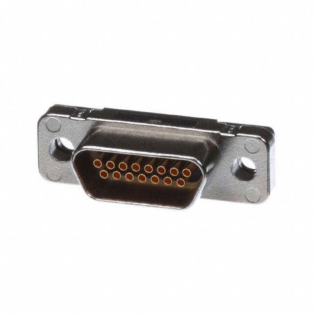
SM2 D-Sub connectors - Stamped and Formed Contacts SURFACE MOUNT CONNECTORS S Specifications N Amphenol SMT D-Sub is offered in C O I I right angle, receptacle with brackets, T • Connectors according to MIL C24308 - NFC 93425-HE5 T S P as an industry standard for I / O I I R R connections. E Materials and Platings C T S C Shells Steel with tin plating E A D Boardlock features: R Insulator High temperature (peak at 260°C) glass-filled A -LIF (Low Insertion Force) boardlock H thermoplastic, UL 94V-0 C especially designed to be fully Socket contact Stamped and formed brass, selected gold in mating area; compatible with pick and place 2.54µm (100µ”) min. tin on termination area, with entire machine. contact under-plated 1.27µm (50µ”) min. nickel -ZeFo (Zero Force Insertion) boardlock Rear insert Brass, 3µm up to 5µm (118µ” up to 197µ”) tinned over has been designed so that once placed nickel 2µm up to 3 µm (78µ” to 118µ”) and expanded, secures a safe locking. Boardlock Tin plating 4µm up to 6µm (157µ” up to 236µ”) over nickel 2µm up to 3µm (78µ” up to 118µ”), insertion force: Low Insertion Force = LIF (bronze) Zero Insertion Force = ZeFo (bronze) DDeessiiggnneedd ffoorr Screwlock Brass, 6µm up to 10µm (236µ” up to 394µ”) tinned over nickel 2µm up to 3µm (78µ” up to 118µ”) PPiicckk aanndd PPllaaccee Grounding Grounding strap: brass, 4µm up to 6µm tin plating over nickel 2µm up to 3µm (78µ” up to 118µ”) SSMMTT pprroocceessss Electrical Data Current rating 3A Voltage rating 300V AC/rms 50Hz Withstanding voltage 1000V AC/rms 50Hz for one minute Insulation resistance 5000MΩ Contact resistance 10mΩ max S • Industrial N Climatic Data IO • Telecom T Operating temperature 85°C, peak at 105°C A • Any industry standard C Damp heat 56 days (40°C - 95% HR) I I / O connections L P P 2 Mechanical Data A E Single contact insertion force 1.2N < F < 2.5N / Single contact withdrawal force 0.4N min 2 LIF boardlock 8N max per connector M Coplanarity of contacts 0.2mm (.008”) max S Mating and unmating force Unit: N No. of Cts Mate (max) Unmate (min) 9 (size E) 30 3.5 15 (size A) 50 4.5 25 (size B) 83 8.0
S Shell Size Dimensions N O I S N E M I D L L A R E V O PCB LAYOUT SHELL mm (inch) SIZE A B C D PITCH F K +0.05 (.002) 0 ±0.1 (.004) 0 -0.1 (.004) -0.2 (.008) -0.25 (.01) E 31.15 (1.226) 16.4 (.645) 25 (.984) 8.03 (.316) 2.74 (.1078) 10.97 (.432) 16.3 (.642) A 39.4 (1.551) 24.8 (.976) 33.3 (1.311) 8.03 (.316) 2.74 (.1078) 19.2 (.756) 24.6 (.968) B 53.3 (2.098) 38.5 (1.515) 47 (1.850) 8.03 (.316) 2.76 (.1086) 33.12 (1.304) 38.3 (1.508)
Panel mounting option A T A D GROUNDING TABS: L A C I N H C E T BOARDLOCKS: FLANGES ACCESSORIES: 2 E / 2 M S
S How to order E T O N L 17 SM2 ... S ... ... ... ... RoHS Compliant packaging: R = reel (100 / reel, 9 Pos only) T = tube configuration: 09 15 contact plating: 25 1 = 0.2µm Au (7.9µ”) 2 = 0.4µm Au (15.7µ”) 3 = 0.5µm Au (19.7µ”) 4 = 0.8µm Au (31.5µ”) board locks / grounding tab: 6 = 1.27µm Au (50µ”) 1 = V1 grounding tab +ZeFo boardlocks (PCB = 1.6) 4 = ZeFo boardlocks only mounting options: (PCB = 1.6) 1 = rear insert 4-40 7 = V1 grounding tab only 2 = rear insert M3 8 = no grounding tab and no 5 = installed front screwlock boardlocks 4-40 B = V2 grounding tab + LIF 6 = fixed front screwlock 4-40 boardlocks (PCB = 1.6) g. n : Standard options n writi d i e For special request, please consult factory ov pr p a Memo nless u d, e bit hi o pr n is o ati plic u d ny A ary. ess ec n m e e d e w ay w ny a n ucts i d o pr ur o dify o m o ht t g e ri h e t erv es We r nly. o e n eli d ui g a as e ar nt e m Do not hesitate to contact us for further information u oc d Amphenol IT & Communication Products n this Block A3/A4, The 4th Industrial District of en i Industrial Headquarters, Dong Keng Road n giv Gong Ming Town, Shen Zhen China atio m Fax:+86(0)755 2754 9955 or nf Technical Support e i h Tel:+86(0)755 2717 7945 T Info-dsub@amphenol.com.cn B http://www.dsubconnector.com 13/ E
D-ST Screw Termination D’Sub series S N C O I I T T S P I I R • Connectors according to: MIL C24308 - NFC 93425-HE5 R E C T S C Materials and platings E A D R A Shells Steel, Tin plated H Insulator Glass filled thermoplastic, UL 94V-0 C Contacts Machined brass for plug full gold Machined bronze for socket, full gold Electrical Data Current rating 7,5 A max Voltage rating 300 V RMS at 50 Hz Withstanding voltage 1000 V RMS at 50 Hz Insulation resistance > 5000 MΩ at 500 V DC Contact resistance < 5 mΩ SSiimmpplliiffyy Climatic Data Operating temperature - 55°C to + 85°C, peak at 125°C YYoouurr ccaabbllee Damp heat 21 days (40°C - 95% HR) Salt spray 48 hours aasssseemmbblliieess!! Mechanical Data Cable type Solid or stranded Cable gage 0.75 mm max ( AWG 18 ) - For bigger wire, please consult factory Screw torque 0.05 mN max Mating cycles 100 (class II) or 500 (class I) S N O I T A C I L P P 3 A E / T S - D
S N O I S N E M I A D L L B 10° A 9,7+ 0.1 R - 0.2 E C V (.382”) O + 0.212,4- 0.2 (.622”) 08- 0.25 (.488”) + 0.258,2 0 (.323”) 011- 0.5 (.433”) + 0.16,9- 0.1 (.272”) 11,6 REF D (.457”) 13 REF (.512”) E Ø1,45 + 0.05- 0.05 24”) 6 0 (.057”) 0, (. + 0.315,8 0 (.622”) 11,1 (.437”) 10,9 (.429”) + 0.315,5 0 (.602”) + 0.16,2- 0.15 (.244”) + 0.15,9- 0.1 (.232”) Cable stripping 3 mm (.118”) A B C D E SIZE +0,25 (,010”) 0 +0,2 (,008”) +0.1 (,004”) +0.1 (,004”) -0.25 (,010”) -0,2 (,008”) 0 -0.1 (,004”) -0,4 (,016”) 30.7 16.4 16.8 25 19.4 9 (1.209”) (.646”) (.661”) (.984”) (.370”) 39 24.8 25.1 33.3 27.7 15 (1.535”) (.976”) (.988”) (1.311”) (1.091”) 52.9 38.5 38.8 47 41.4 25 (2.083”) (1.516”) (1.528”) (1.850”) (1.630”) 69.2 54.9 55.3 63.5 57.9 37 (2.724”) (2.161”) (2.177”) (2.500”) (2.280”)
How to order R E D R O O T W O H RoHS Compliant Plastic hoods Metallic hoods 3 E / T S - D
TF D-Sub connectors - Stamped and Formed Contacts PRESS FIT STRAIGHT PCB TERMINATION S N The Amphenol “TF“ series C Materials and Platings O I I features eye of needle formed T Shells Steel, tin plated T S P contacts, and insulator with I Insulator Glass-filled thermoplastic, UL 94V-0 I R R closed entry contacts cavities. E Pin contact Brass, selected gold in mating area; C T S C 2.54µm (100µ") min. tin E A on termination area over D This series gives you R A 1.27µm (50µ") min.nickel Amphenol's high standards of H C Socket contact Phosphor bronze, selected gold in quality and reliability to meet mating area; 2.54µm (100µ") min. all your technical requirements. tin on termination area over; 1.27µm(50µ") min. nickel Rear insert Brass, 2.54µm (100µ") min. nickel plated Boardlock Brass, 2.54µm (100µ") min. nickel plated Screwlock Brass, 2.54µm (100µ") min. nickel plated Electrical Data SSoollddeerrlleessss Current rating 3A ssttrraaiigghhtt PPCCBB Voltage rating 300V AC Withstanding voltage 1000V AC/rms 60Hz for one minute Insulation resistance 1000MΩ mmoouunntt Contact resistance 25mΩ max ccoonnnneeccttoorrss Climatic Data Operating temperature -55°C to +125°C Salt spray 24 hours S • Industrial N Mechanical Data IO • Telecom T Single contact insertion force ≤ 3.60 N A • Any backplanes C Single contact withdrawal force ≥ 0.2 N I connections Single contact insertion on board ≤ 100 N L P Single contact withdrawal from board ≥ 20 N P A Standard plating thickness Gold flash 4 E 0.4µm (15µ") gold 0.76µm (30µ") gold / F T Terminal Boardlock Specification Specification Finished Hole 1 (+0.09 -0.06) 3.1 +/- 0.05 mm Cu > 25 µm Min 25 µm Sn < 15 µm 5-15 µm
S Socket version N O I S N 10 E A 6. M I D B L L A C R 0 E 6. V 4 O 2.8 7.9 10.2 12.55 2.77 8 3. Plug version A 5 9 3 5. 3. B 0 C 6. 4 8 2. 8.36 12.55 2.77 4 3. 24.99 2.77 4 2 8 4 2. 1. 2 4 1. Position n1 for plug Position n1 for socket For PCB holes diameters, see on page 1 (finished holes) Nb OF DIMENSIONS mm (inch) CONTACTS A B C plug C socket 9 30.81 (1.185) 24.99 (0.984) 16.92 (0.666) 16.33 (0.643) 15 39.14 (1.54) 33.32 (1.312) 25.50 (1.004) 24.66 (0.97) 25 53.04 (2.088) 47.04 (1.852) 28.96 (1.534) 38.38 (1.511) 37 69.32 (2.729) 63.50 (2.5) 55.42 (2.182) 54.84 (2.16)
G N I L O O T T I F - S 1 S 0. E ± R 6 P 2 Female Size of connectors Tooling PN 9 981 MC 15 982 MC 25 983 MC 37 984 MC Male 4 E / F T Size of connectors Tooling PN 9 985 MC 15 986 MC 25 987 MC 37 988 MC
S Board mounting option E T O N Option 0 Option 1 3.10mm (.122”) Press Fit Boardlock Flange mounting option M3 / #4 - 40 UNC Screwlock M3 / #4 - 40 UNC Threaded holes g. n writi n d i e ov pr Option 1 or 4 Option 2 or 5 ap ess nl u d, e bit How to order ohi pr n is o L 17TF ... ... ... ... ... ... plicati u d ny A ary. RoHS Compliant Flange mounting option : ess ec 1 = #4-40 threaded hole m n Series 2 = #4-40 threaded hole with dee #4-40 UNC screwlock we installed way Number of contacts : 4 = M3 threaded hole any n 09-15-25-37 5 = M3 threaded hole with ucts i M3 scewlock installed d o pr ur o Contact type: dify o 1 = pin m 0 = socket Board mounting option ht to 0 = without boardlock e rig 1 = with boardlock e th erv Contact plating es 01 == g0o.4ld µ fmla s(1h5µ”) F1 r=o ntitn s ohveellr p nlaictkinegl only. We r 2 = 0.76 µm (30µ”) ne eli d ui g a as e ar nt e m Do not hesitate to contact us for further information u oc d Amphenol IT & Communication Products n this Block A3/A4, The 4th Industrial District of en i Industrial Headquarters, Dong Keng Road n giv Gong Ming Town, Shen Zhen China atio m Fax:+86(0)755 2754 9955 or nf Technical Support e i h Tel:+86(0)755 2717 7945 T Info-dsub@amphenol.com.cn E http://www.dsubconnector.com 4/ E
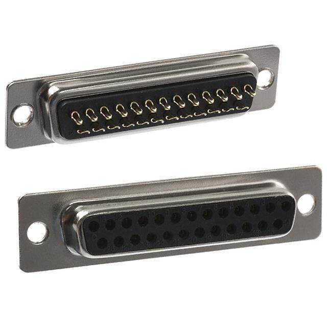
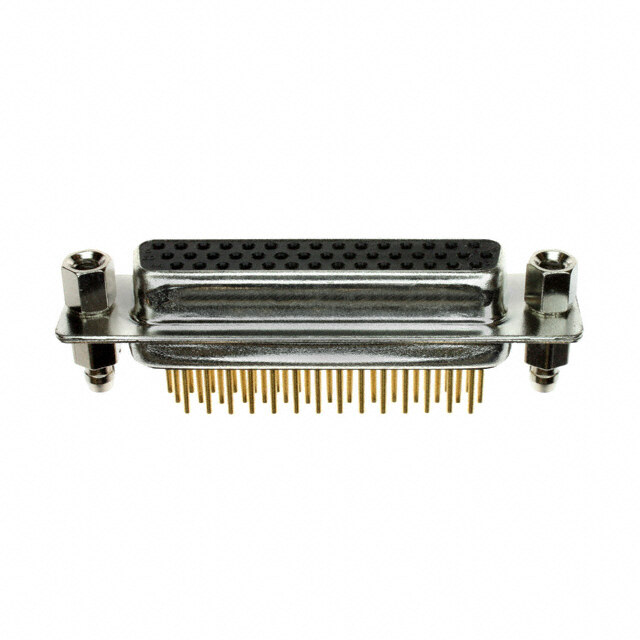
SD D'Sub connectors - Stamped and Formed Contacts SOLDER-CUP TERMINATION STANDARD and HIGH DENSITY S Specifications N The Amphenol "SD" series features C O I I precision formed contacts, and T • Connectors according to: MIL C24308 - NFC 93425-HE5 T S P insulator with closed entry contacts I I R R cavities. E C T Materials and Platings S C E A Shells Steel, tin over nickel plating D This series gives you Amphenol's R A Insulator Glass-filled thermoplastic, UL 94V-0 high standards of quality and reliability H C Pin contacts Brass, selected gold in mating area; to meet all of your commercial 2.54µm (100µ") min. tin requirements. on termination area over 1.27µm (50µ") min. nickel Socket contact Phosphor bronze, selected gold in mating area; 2.54µm (100µ") min. tin- on termination area over 1.27µm (50µ") min. nickel Rear insert Brass, 2.54µm (100µ") min. nickel plated Screwlock Brass, 2.54µm (100µ") min. nickel plated EEccoonnoommiiccaall Electrical Data ssoollddeerr ccuupp Current rating Standard Density: 5A High Density: 3A Voltage rating 250V AC/rms 50Hz ccoonnnneeccttoorrss Withstanding voltage 1000V AC/rms 50Hz for one minute Insulation resistance 1000MΩ at 500V DC Contact resistance 20mΩ max Climatic Data Operating temperature -55°C to +125°C S • Industrial Salt spray 24 hours N O I • Telecom T Mechanical Data A • Any industry standard C I I / O connections Single contact insertion force 0.54kg (1.19lb) max L Single contact withdrawal force SD : 0.06kg (0.13lb) min P P HD : 0.02kg (0.044lb) min A 5 Mating and unmating force E Unit: kg ( lb) / D No. of Cts SD HD S SD HD Mate (max) Unmate (min) Mate (max) Unmate (min) 9 15 3.05 (6.74) 0.36 (0.79) 3.81 (8.42) 0.52 (1.14) 15 26 5.09 (11.24) 0.46 (1.01) 5.95 (13.16) 1.05 (2.32) 25 44 8.44 (18.66) 0.81 (1.8) 9.26 (20.46) 1.37 (3.02) 37 62 12.51 (27.65) 1.1 (2.47) 13.48 (29.78) 1.76 (3.88) 50 78 14.65 (32.38) 1.6 (3.56) 15.82 (34.96) 2.02 (4.46) Standard plating thickness • gold flash • 0.4µm (15µ") gold • 0.76 µm (30µ") gold
S Standard Density N O I S EN A±0.38 (.015) 5) M 01 DI 05) B±0.13 (.005) ±0. 05) 0 4 0 OVERALL 2.84 (.112) 8.38±0.13 (.33±0. C±P0E.O±1DS03±. I0(T0.50I.O1 0(3.N50 )( 0#.0210)5) 12.55±0.38 (.49 7.9±0.13 (.311±0. 10° X Ø3.05 (.120 dia) 8) 1 1 3 (. 32) PLUG SOCKET 0) 5.9 (.211 (.433)12.3 (.484) F±0.13 (.005) 12.5 (.492) 11.2 (.441) 6.1 (.24 10.72 (.422) Nb OF DIMENSIONS mm (inch) CONTACTS A B CD E FX 9 30.84 (1.21) 24.99 (.98) 16.92 (.67) 16.24 (.64) 11.09 (.44) 19.28 (.76) 2.74 15 39.24 (1.54) 33.32 (1.31) 24.7 (.972) 24.56 (.97) 19.39 (.76) 27.51 (1.08) 2.74 25 53.04 (2.09) 47.04 (1.85) 38.96 (1.53) 38.38 (1.51) 33.24 (1.31) 41.30 (1.63) 2.77 37 69.32 (2.73) 63.50 (2.50) 55.42 (2.18) 54.76 (2.16) 49.86 (1.96) 57.71 (2.27) 2.77 50 67 (2.64) 61.11 (2.41) 52.86 (2.08) 52.34 (2.06) 44.32 (1.75) 55.3 (2.18) 2.77 A±0.38 (.015) 5) B±0.13 (.005) 5) 15) 0 0 0 0.0 C±0.13 (.005) 0.0 ±0. ± ± 5 1 9 0 4 2 6 11.2±0.13 (.4 2.84 (.112) PEO±S0DI.T1±I30O .(N1.03 #0 (15.0)05) 10.9±0.13 (.4 15.37±0.38 (. 4 8 10° 2. X Ø3.05 (.120 dia) 8) 1 1 PLUG SOCKET 3 (. 2) 5.9 (.2311 (.433) 12.3 (.484) F±0.38 (.015) 12.5 (.492) 11.2 (.441)6.1 (.240) 13.56 (.534)
High Density S N O I S N E ±0.005) AB±±00..3183 ((..001055)) 1±0.005) 494±0.015) ALL DIM 8.38±0.13 (.33 1.98 (.078) C±P0O.D1S3±IT 0(I..O0103N5 ()#.0105) 7.9±0.13 (.31 12.55±0.38 (. OVER 8 1.9 Ø3.05 (.120) 10° 2.29±0.05 (.09±0.002) 12 (.472) 11 (.433) 5.9 (.232) PLUG SOCKET6.1(.240) 11.2 (.441) 12.2 (.48) 3 (.118) 7) 9 E±0.13 (.005) 5 (.1 10.72 (.422) Nb OF DIMENSIONS mm (inch) CONTACTS A B CD E 15 30.84 (1.21) 24.99 (.98) 16.92 (.67) 16.24 (.64) 19.28 (.76) 26 39.24 (1.54) 33.32 (1.31) 24.7 (.972) 24.56 (.97) 27.51 (1.08) 44 53.04 (2.09) 47.04 (1.85) 38.96 (1.53) 38.38 (1.51) 41.30 (1.63) 62 69.32 (2.73) 63.50 (2.50) 55.42 (2.18) 54.76 (2.16) 57.71 (2.27) 78 67 (2.64) 61.11 (2.41) 52.86 (2.08) 52.34 (2.06) 55.3 (2.18) A±0.38 (.015) 0.005) 4 (.246) CB±±00..1133 ((..000055)) ±0.005) 5±0.015) ± 2 9 0 13 (.441 82)x3=6. 45.79±D0±.01.31 3(1 (..800035±)0.005) 0.13 (.42 ±0.38 (.6 2±0. 8 (.0 POSITION #1 0.9± 5.37 11. 2.0 1 1 5 E / 10° Ø3.05 (.120) D 2.41 (.95) S 12 (.472)11 (.433) 5.9 (.232) PLUG SOCKET 6.1(.240) 11.2 (.441) 12.2 (.48) 3 (.118) E±0.38 (.015) 7) 9 1 33.56 (.534) 5 (. 78 CONTACTS
S Panel mounting option E T O N M3 or #4-40 screwlock M3 or #4-40 5.8 (.228) 6.0 (.236) Front Female Screwlock Threaded Rear Insert VF / VFM H / G g. n How to order writi n d i e L ... ... ... ... ... ... ...C309 ov pr p a ess RoHS Compliant plating option: d, unl e valid only for bit hi 77: tinned shell 0.76µm (30µ") pro gold for receptable part numbers to be written on is flash 7 17: t+in dniemdp slehsell as follow: uplicati d for plug or 77...................C309 Any 717.................C309 ary. 177: tinned shell ess for receptable ec 0.4µm 777: tinned shell front mounting type: em n (15µ") no digit = standard rivet de + dimples e for plug 3.05mm ay w VF = front screwlock 4-40 ny w VFM = front screwlock M3 n a SD : standard density ucts i HD : high density od contact type: pr P = pin our shell size: E, A, B, C, D S = socket modify o ht t rHe a=r r meaor uinnsteinrtg 4 t-y4p0e: cSHoDDn ::f i91g,5u1,r52a,62t,i54o,4n3,:76,25,078 erve the rig G = rear insert M3 es We r nly. For special request, please consult factory e o n eli d ui g a as e ar nt e m Do not hesitate to contact us for further information u oc d Amphenol IT & Communication Products n this Block A3/A4, The 4th Industrial District of en i Industrial Headquarters, Dong Keng Road n giv Gong Ming Town, Shen Zhen China atio m Fax:+86(0)755 2754 9955 or nf Technical Support e i h Tel:+86(0)755 2717 7945 T Info-dsub@amphenol.com.cn F http://www.dsubconnector.com 5/ E
SD D'Sub connectors - Stamped and Formed Contacts STRAIGHT PCB TERMINATION STANDARD and HIGH DENSITY S Specifications N The Amphenol "SD" C O I I series features precision T • Connectors according to: MIL C24308 - NFC 93425-HE5 T S P formed contacts, and I I R Materials and Platings R insulator with closed E C T S entry contacts cavities. C Shells Steel, tin over nickel plating E A D This series gives you R Insulator Glass-filled thermoplastic, UL 94V- 0 A Amphenol's high H Pin contacts Brass, selected gold in mating area; C 2.54µm (100 µ") min.tin on standards of quality and termination area over 1.27µm reliability to meet all of (50µ") min.nickel your commercial Socket contact Phosphor bronze, selected gold in requirements. mating area;2.54µ(100µ") min.tin on termination area over 1.27µm (50µ") min.nickel Rear insert Brass, 2.54µm (100µ") min.nickel plated Boardlock Brass, 2.54µm (100µ") min.nickel plated Screwlock Brass, 2.54µm (100µ") min.nickel plated (removable) EEccoonnoommiiccaall Electrical Data ssttrraaiigghhtt PPCCBB Current rating Standard Density:5A High Density:3A mmoouunntt ccoonnnneeccttoorrss Voltage rating 250V AC/ rms 50Hz Withstanding voltage 1000V AC/rms 50Hz for one minute Insulation resistance 1000MΩ at 500V DC Contact resistance 20mΩ max Climatic Data Operating temperature -55°C to +125°C S • Industrial Salt spray 24 hours N O I • Telecom T Mechanical Data A • Any industry standard C Single contact insertion force 0.54kg (1.19lb) max LI I / O connections Single contact withdrawal force SD : 0.06kg (0.13lb) min P P HD : 0.02kg (0.044lb) min A 6 Mating and unmating force E Unit: kg ( lb) / D No. of Cts SD HD S SD HD Mate (max) Unmate (min) Mate (max) Unmate (min) 9 15 3.05 (6.74) 0.36 (0.79) 3.81 (8.42) 0.52 (1.14) 15 26 5.09 (11.24) 0.46 (1.01) 5.95 (13.16) 1.05 (2.32) 25 44 8.44 (18.66) 0.81 (1.8) 9.26 (20.46) 1.37 (3.02) 37 62 12.51 (27.65) 1.1 (2.47) 13.48 (29.78) 1.76 (3.88) 50 78 14.65 (32.38) 1.6 (3.56) 15.82 (34.96) 2.02 (4.46) Standard plating thickness • gold flash • 0.381µm (15µ") gold • 0.76 µm (30µ") gold
S Standard Density N O I NS 5) A±0.38 (.015) E 00 B±0.13 (.005) IM ±0. C±0.13 (.005) D 3 12.55±0.38 (.494±0.015) LL 13 (.3 78) ED±±00..0153 ((..000025)) 7.9±0.13 (.311±0.005) ERA 38±0. 84 (.0 POSITION #1 OV 8. 2. 4.4 (.173) 0.4 (.016) ø 0.62 (.024) 10° X 5.9 (.232) DETAIL A J* PLUG SOCKET 6.1 (.240) F±0.13 (.005) 10.72 (.422) A * see chart "panel mounting option" Nb OF DIMENSIONS mm (inch) CONTACTS A B CD E FX 9 30.84 (1.21) 24.99 (.98) 16.92 (.67) 16.24 (.64) 11.09 (.44) 19.28 (.76) 2.74 15 39.24 (1.54) 33.32 (1.31) 24.7 (.972) 24.56 (.97) 19.39 (.76) 27.51 (1.08) 2.74 25 53.04 (2.09) 47.04 (1.85) 38.96 (1.53) 38.38 (1.51) 33.24 (1.31) 41.30 (1.63) 2.77 37 69.32 (2.73) 63.50 (2.50) 55.42 (2.18) 54.76 (2.16) 49.86 (1.96) 57.71 (2.27) 2.77 50 67 (2.64) 61.11 (2.41) 52.86 (2.08) 52.34 (2.06) 44.32 (1.75) 55.3 (2.18) 2.77 A±0.38 (.015) B±0.13 (.005) 5) 15) 0.005) C±0.13 (.005) ±0.00 5±0.0 ± 9 0 13 (.441 12) E±0.1D3 ±(.00.0153) (.005) 0.13 (.42 ±0.38 (.6 11.2±0. 2.84 (.1 POSITION #1 10.9± 15.37 4 8 10° 2. X 5.9 (.232) 13.56 (.534) 3) 7 1 4 (. J PLUG SOCKET 4. 6.1 (.240) F±0.38 (.015) 50 CONTACTS
High Density S N O I A±0.38 (.015) 5) 015) ENS 38±0.13 (.33±0.005) 98 (.078) CP±BO0D±.S1±0I3T0. 1I.(O13.03 N(0 .( 50.#0)01055)) 7.9±0.13 (.311±0.00 12.55±0.38 (.494±0. OVERALL DIM 8. 1. 8 9 1. 10° 2.29±0.05 (.09±0.002) 2) 5.9 (.23 J* PLUG SOCKET 6.1(.240) 4.2 (.165) E±0.13 (.005) * see chart "panel mounting option" 10.72 (.422) Nb OF DIMENSIONS mm (inch) CONTACTS A B CD E 15 30.84 (1.21) 24.99 (.98) 16.92 (.67) 16.24 (.64) 19.28 (.76) 26 39.24 (1.54) 33.32 (1.31) 24.7 (.972) 24.56 (.97) 27.51 (1.08) 44 53.04 (2.09) 47.04 (1.85) 38.96 (1.53) 38.38 (1.51) 41.30 (1.63) 62 69.32 (2.73) 63.50 (2.50) 55.42 (2.18) 54.76 (2.16) 57.71 (2.27) 78 67 (2.64) 61.11 (2.41) 52.86 (2.08) 52.34 (2.06) 55.3 (2.18) A±0.38 (.015) B±0.13 (.005) 0.005) 4 (.246) 45.79±0.13 (1.803±.005) 5±0.015) 0.005) ± 2 C±0.13 (.005) 0 ± 3 (.441 2)x3=6. D±0.13 (.005) 0.38 (.6 3 (.429 1 8 ± 1 11.2±0. 2.08 (.0 POSITION #1 15.37 10.9±0. 6 E 10° 2.41 (.095) / 0) D 232) 1 (.24 S 9 (. 6. 5. J PLUG SOCKET 5) 6 1 2 (. 4. E±0.38 (.015) 13.56 (.534) 78 CONTACTS
R Panel mounting option E D R O O M3 or # 4-40 screwlock M3 or # 4-40 H = # 4-40 T G = M3 W H = # 4-40 O G = M3 H )8 J X X 2 2 (.8 Y Y 4.8 (.189) 5. 5.9 (.232) Front Female Screwlock Threaded Rear Insert RM5 Standoff Boardlock RM8 Standoff Boardlock RM5 RM5G RM8 RM8G X 6.0(.236) 12.7(.500) Y 4.2(.165) 3.2(.126) J 6.2(.244) 10.1(.397) How to order L ... ... ... ... ... ... OL2 ...C309 g. n RoHS Compliant plating option: writi valid only for d in e 77: tinned shell 0.76µm (30µ") prov p gflaosldh 717: ftoinrn reedc esphtealblle part numabse rfos lltoow b:e written unless a + dimples d, for plug or 7771.7...................................CC330099 ohibite pr 177: tinned shell n is o 0(1.45µµm") 7 77: ft+oin rdn iremedcp eslephstealblle gn roo duingdi ti n=g s3 tt.aa0nb5dsma:mrd rivet Any duplicati for plug RM5 = retention clip ary. RM8 = retention clip ecess SD : standard density + front screwlock m n e e HD : high density e d w Termination ay w Straight for PCB ny shell size: E, A, B, C, D n a contact type: ucts i d mHG o==u rrneetaairnr iginn sstyeeprrtte 4M:-430 PS == psoincket odify our pro m H,G must also be used configuration: ht to to specify the threading SD : 9,15,25,37,50 e rig of RM5 or RM8 HD : 15,26,44,62,78 e th grounding tabs. erv es We r nly. For special request, please consult factory e o n eli d ui g a as e ar nt e m Do not hesitate to contact us for further information u oc d Amphenol IT & Communication Products n this Block A3/A4, The 4th Industrial District of en i Industrial Headquarters, Dong Keng Road n giv Gong Ming Town, Shen Zhen China atio m Fax:+86(0)755 2754 9955 or nf Technical Support e i h Tel:+86(0)755 2717 7945 T Info-dsub@amphenol.com.cn F http://www.dsubconnector.com 6/ E
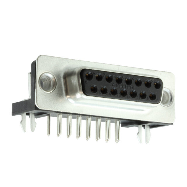
SD D’Sub connectors - Stamped and Formed Contacts RIGHT ANGLE BOARD MOUNT CONNECTORS S Specifications N The Amphenol “SD” series features C O I I precision formed contacts and T • Connectors according to: MIL C24308 - NFC 93425-HE5 T S P boardlocks. I I R R E C T Materials and Platings S This series gives you Amphenol’s high C E RA Shells Steel, tin over nickel plating D standards of quality and reliability to A Insulator Glass-filled thermoplastic, UL 94V- 0 meet all of your commercial H C Pin contacts Brass, selected gold in mating area; requirements. N 2.54µm (100 µ") min.tin on I A termination area over 1.27µm M (50µ") min.nickel Socket contact Phosphor bronze, selected gold in mating area;2.54µ(100µ") min.tin on termination area over 1.27µm (50µ") min.nickel Rear insert Brass, 2.54µm (100µ") min.nickel plated Boardlock Phosphor bronze or Brass, 2.54µm EEccoonnoommiiccaall (100µ") min.nickel plated Screwlock Brass, 2.54µm (100µ") min.nickel plated rriigghhtt aannggllee PPCCBB Electrical Data mmoouunntt Current rating 5A Voltage rating 250V AC/ rms 50Hz ccoonnnneeccttoorrss Withstanding voltage 1000V AC/rms 50Hz for one minute Insulation resistance 1000MΩ at 500V DC Contact resistance 15mΩ max Climatic Data Operating temperature -55°C to +125°C S • Industrial Salt spray 24 hours N O I • Telecom T Mechanical Data A • Any industry standard C I I / O connections Single contact insertion force 0.54kg (1.19lb) max L Single contact withdrawal force 0.06kg (0.13lb) min P P A 7 Mating and unmating force E Unit: kg ( lb) / D A4 Style 1A Style S No. of Cts Mate (max) Unmate (min) Mate (max) Unmate (min) 9 3.05 (6.74) 0.36 (0.79) 4.6 (10.17) 0.4 (0.88) 15 5.09 (11.24) 0.46 (1.01) 7.7 (17.02) 0.5 (1.10) 25 8.44 (18.66) 0.81 (1.8) 12.7 (28.07) 0.8 (1.77) 37 12.51 (27.65) 1.1 (2.47) 17.7 (39.12) 1.2 (2.65) Standard plating thickness • gold flash • 0.381µm (15µ") gold • 0.76 µm (30µ") gold
S A4 style (MIL Footprint) N O I S N E M I D L L A R E V O 8) 1 3 8 (. 0 8. Nb OF DIMENSIONS mm (inch) CONTACTS A B C D E F 9 30.84 (1.21) 24.99 (.98) 16.92 (.67) 16.24 (.64) 11.09 (.44) 2.74 (.108) 15 39.14 (1.54) 33.32 (1.31) 25.25 (.99) 24.56 (.97) 19.39 (.76) 2.74 (.108) 25 53.04 (2.09) 47.04 (1.85) 38.96 (1.53) 38.38 (1.51) 33.24 (1.31) 2.77 (.109) 37 69.32 (2.73) 63.50 (2.50) 55.42 (2.18) 54.76 (2.16) 49.86 (1.96) 2.77 (.109) 1A style (European Footprint) Nb OF DIMENSIONS mm (inch) CONTACTS A B C D E F 9 30.84 (1.21) 24.99 (.98) 16.92 (.67) 16.24 (.64) 11.96 (.43) 2.74 (.108) 15 39.1 (1.54) 33.32 (1.31) 25.25 (.99) 24.66 (.97) 19.18 (.755) 2.74 (.108) 25 53.09 (2.09) 47.04 (1.85) 38.96 (1.53) 38.38 (1.51) 33.24 (1.31) 2.77 (.109) 37 69.4 (2.73) 63.50 (2.50) 55.42 (2.18) 54.84 (2.16) 49.86 (1.96) 2.77 (.109)
Panel mounting option R E D R O O T W O H How to order L ... SD ... ... ... ... CH ...C309 RoHS Compliant plating option: valid only for 0.76µm (30µ") 77: tinned shell for receptable part numbers to be written gold 717: tinned shell as follow: flash + dimples 77 SD...................C309 for plug or 717 SD.................C309 177: tinned shell for receptable mounting options: 0.4µm 777: tinned shell 4F = front screwlock 4-40 (15µ") + dimples 3F = front screwlock M3 for plug 4R = rear insert 4-40 3R = rear insert M3 shell size: E, A, B, C 7 PCB locking type: E configuration: 9, 15, 25, 37 grounding tabs / + board locks D contact type: S P = pin Footprint: S = socket 1A (European) A4 (MIL) For special request, please consult factory
SD D-Sub connectors - Stamped and Formed Contacts RIGHT ANGLE BOARD MOUNT CONNECTORS FOOTPRINT 14.99 mm (.590”) S Specifications N The Amphenol "SD" series features C O I I precision formed contacts and T • UL File: E119881 T S P boardlocks. I • Connectors according to MIL C24308 I R R E C T Materials and Platings S This series gives you Amphenol's high C E A D standards of quality and reliability to R Shells Steel, tin over nickel plating A Insulator Glass-filled thermoplastic, UL 94V-0 meet all of your commercial H C Pin contacts Brass, selected gold in mating area; requirements. 2.54µm (100µ") min. tin on termination area over 1.27µm (50µ") min. nickel Socket contact Phosphor bronze, selected gold in mating area; 2.54µm (100µ") min. tin- on termination area over 1.27µm (50µ") min. nickel Rear insert Brass, 2.54µm (100µ") min. nickel plated Screwlock Brass, 2.54µm (100µ") min. nickel plated EEccoonnoommiiccaall Electrical Data rriigghhtt aannggllee PPCCBB Current rating 5A Voltage rating 600V AC/rms 50Hz mmoouunntt ccoonnnneeccttoorrss Withstanding voltage 1000V AC/rms 50Hz for one minute Insulation resistance 5000MΩ Contact resistance 10mΩ max Climatic Data S • Industrial Operating temperature -55°C to +125°C N Salt Spray 24 hours IO • Telecom T A • Any industry standard C I I / O connections L Mechanical Data P P Mating and unmating force A 8 Unit: kg ( lb) E / D No. of Cts Mate (max) Unmate (min) S 9 (size E) 3.05 (6.74) 0.36 (0.79) 15 (size A) 5.09 (11.24) 0.46 (1.01) 25 (size B) 8.44 (18.66) 0.81 (1.8) 37 (size C) 12.51 (27.65) 1.1 (2.47) Standard plating thickness • gold flash • 0.4µm (15µ") gold • 0.76 µm (30µ") gold
S Shiell Size Dimensions N O I S N E M A±0.38 (.015) I D B±0.13 (.005) L L C±0.25 (.01) A R E D±0.25 (.01) V O POSITION #1 0) 2) 1) 3 1 1 3 1 3 8.38 (. 10° 0.64*0.64 (.025*.025) 2.84 (. 7.9 (. 40) X 2 1 (. 12.55 (.494) 5) 6. 1 3 8 (. 12.1 (.476) 4.99 (.590) 25.08 (.987) 1 2) 3.18 (.125) 1 1 4 (. 8 2. Recommended P.C.B.Layout 12) E±0.13 (.005) 4 (.1 E±0.13 (.005) 8 2. E±0.13 (.005) 1.385 (.054) X 5) 7 2 9 (. B±0.13 (.005) 9 6. Nb OF DIMENSIONS mm (inch) CONTACTS A B C D E X 9 30.84 (1.214) 24.99 (.984) 16.92 (.666) 16.26 (.640) 11.08 (.436) 2.74 15 39.24 (1.545) 33.32 (1.312) 25.25 (.994) 24.56 (.967) 19.39 (.763) 2.74 25 53.04 (2.088) 47.04 (1.852) 38.96 (1.534) 38.30 (1.508) 33.24 (1.309) 2.77 37 69.34 (2.730) 63.50 (2.500) 55.42 (2.182) 54.76 (2.156) 49.86 (1.963) 2.77
Panel mounting option R E D R O O #4-40 or M3 T W O H 8) 2 2 8 (. 5. #4-40 or M3 Front Female Screwlock Threaded Rear Insert 4F/3F 4R/3R How to order L ... SD ... ... ... AB CH ...C309 RoHS Compliant plating option: valid only for 77: tinned shell 0.76µm (30µ") for receptable gold 717: tinned shell part numbers to be written flash + dimples as follow: for plug 77SD...................C309 or 177: tinned shell 717SD.................C309 for receptable 0.4µm 777: tinned shell (15µ") + dimples mounting options: for plug 4F = front screwlock 4-40 3F = front screwlock M3 8 shell size: E, A, B, C 4R = rear insert 4-40 E 3R = rear insert M3 / D configuration: 09, 15, 25, 37 S PCB locking type: grounding tabs + boardlocks contact type: P = pin S = socket footprint:14.99 mm (.590”) For special request, please consult factory
TS D-Sub connectors - Stamped and Formed Contacts STRAIGHT PCB TERMINATION ONE METAL SHELL CONNECTORS S Specifications N The one shell D-sub Amphenol series C O I I features, stamped and formed contacts. T • Connectors according to MIL C24308 T S P I I R R This series gives you Amphenol’s high E C T S standards of quality and reliability C E A Materials and Platings D to meet all of your commercial R A Shells Steel, tin over nickel plating requirements H C Insulator Glass-filled thermoplastic, UL 94V-0 Contacts Copper alloy, with selective gold plating Boardlock Brass with nickel plating Screwlock Brass with nickel plating Electrical Data Current rating 5A Voltage rating 600V AC/rms 50Hz EEccoonnoommiiccaall Withstanding voltage 1000V AC/rms 50Hz for one minute Insulation resistance 5000MΩ ssttrraaiigghhtt PPCCBB,, Contact resistance 10mΩ max oonnee sshheellll Climatic Data ccoonnnneeccttoorrss Operating temperature -55°C to +125°C Mechanical Data Mating and unmating force S • Industrial N Unit: kg ( lb) O I • Telecom T A • Any industry standard No. of Cts Mate (max) Unmate (min) C I I / O connections L 9 3.05 (6.74) 0.36 (0.79) P 15 5.09 (11.24) 0.46 (1.01) P A 0 25 8.44 (18.66) 0.81 (1.8) 1 37 12.51 (27.65) 1.1 (2.47) E / S Standard plating thicknesses • gold flash T • 0.4µm (15µ") gold • 0.76 µm (30µ") gold
S Shell Size Dimensions N O I S N E M I D L A±0.38 (.015) 5) OVERAL 8±0.13 (.33±.005) 4 (.112) PDCBO±±±S000...I111T333IO (((.N..000 000#5551))) 7.9±0.13 (.311±.005) 12.55±0.38 (.494±.01 3 8 8. 2. 10° X 4.8 (.189) 5) 2 1 8 (. 1 PLUG SOCKET 3. L* 0) 4 2 1 (. 6. 7.7 (.303) 0.8 (.031) *see chart "how to order" RECOMMENDED P.C.B. LAYOUT B E ø3.2 (.126) C L 0) ø1.0 (.039) 1.385 (.055) 6 5 2 (. X 4 1. Nb OF DIMENSIONS mm (inch) CONTACTS A B C D E X 9 30.84 (1.21) 24.99 (.984) 16.92 (.666) 16.26 (.640) 11.08 (.436) 2.74 15 39.24 (1.54) 33.32 (1.31) 25.25 (.994) 24.56 (.967) 19.39 (.763) 2.74 25 53.04 (2.09) 47.04 (1.85) 38.96 (1.53) 38.30 (1.51) 33.24 (1.31) 2.77 37 69.34 (2.73) 63.50 (2.50) 55.42 (2.18) 54.76 (2.16) 49.86 (1.96) 2.77
Panel mounting option R E #4-40 or M3 D R O #4-40 or M3 O T W O H 6) 3 2 0 (. 6. ø3.25 (.128) ø3.25 (.128) Boardlock with Threaded Insert Boardlock with Front Screwlock RM5 RM8 ø3.05 (120”) Rear Insert M3 or #4-40 Clear Hole Rear Insert Threaded How to order L ... TS ... ... ... ... ... ... C309 RoHS Compliant plating option: valid only for 0.76µm (30µ") 77: tinned shell for receptable part numbers to be written gold 717: tinned shell as follow: flash + dimples 77...................C309 for plug or 717.................C309 177: tinned shell for receptable 0.4µm 777: tinned shell (15µ") board mounting options: + dimples Blank = Clear Hole for plug RM5 = retention clip RM8 = retention clip shell size: E, A, B, C +front screwlock mounting options: 0 termination: 1 Blank = Clear Hole OL2 : L = 6.02mm (.237”) E G = M3 OL2C : L = 11.48mm (.452”) / H = 4.40 S H,G must also be used to specify T the threading of RM5 or RM8 contact type: grounding tabs P = pin S = socket configuration: 09, 15, 25, 37 For special request, please consult factory
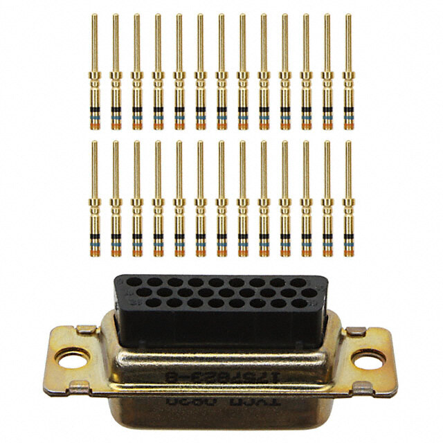
RR-HR D-Sub connectors - Stamped and Formed Contacts REAR RELEASE CRIMP CONNECTORS S Specifications N Designed for high volume C O I I production, Amphenol's rear T • Connectors according to MIL C24308 T S P release crimp connector and I I R R contacts provide significant cost E Materials and Platings C T S saving. C E A Shells Tinned steel with or without dimples D R A on plug connector - EMI / RFI shell configuration. H C Insulator Black glass-filled thermoplastic, UL 94V-0 - Removable, reusable contacts. Boardlock Brass, 3µm to 5µm (118µ" to 197µ") - Automatic and manual tooling tin over nickel 2µm to 3µm available. (78µ" to 118µ") Screwlock Brass, 6µm to 10µm (236µ" to 394µ") tin over nickel 2µm to 3µm (78µ" to 118µ") Contacts Under plating Crimp side 0.2µm (8µ") gold 2µm (78µ") nickel gold flash or tin SSiimmpplliiffyy 0.5µm (20µ") gold 2µm (78µ") nickel gold flash or tin 0.76µm (30µ") gold 2µm (78µ") nickel gold flash or tin yyoouurr ccaabbllee Electrical Data aasssseemmbblliieess Current rating 5A Voltage rating 500V AC/rms 50Hz Withstanding voltage RR: 1000V AC/rms 50Hz for 1 minute HR: 1000V AC/rms 60Hz for 1 minute Insulation resistance RR: 5000MΩ HR: 1000MΩ S • Commercial Contact resistance 10mΩ max N O Wire size 20-28 AWG max insulation I • Industrial Ø1.27mm (.05") T A • Telecom C I L • Any industry standard P 1 Climatic Data P I / O connections 1 A E Operating temperature -55°C to +125°C / R Mechanical Data H - Mating and unmating force R Unit: kg ( lb) R No. of Cts Mate (max) Unmate (min) RR HR RR HR RR HR 9 (size E) 15 (size E) 3.05 (6.74) 3.81 (8.42) 0.36 (0.79) 0.52 (1.14) 15 (size A) 26 (size A) 5.09 (11.24) 5.95 (13.16) 0.46 (1.01) 1.05 (2.32) 25 (size B) 44 (size B) 8.44 (18.66) 9.26 (20.46) 0.81 (1.8) 1.37 (3.02) 37 (size C) 62 (size C) 12.51 (27.65) 13.48 (29.78) 1.1 (2.47) 1.76 (3.88) 50 (size D) 78 (size D) 14.65 (32.38) 15.82 (34.96) 1.6 (3.56) 2.02 (4.46)
S Standard density RR N O I S N A±0.38 (.015) IME B±0.13 (.005) 5) 015) OVERALL D 8±0.13 (.33±.005) 4 (.112) PEDCO±±±000S...I011T533IO (((...N0000 00#2551))) 7.9±0.13 (.311±.00 12.55±0.38 (.494±. 3 8 8. 2. 10° ø3.05 (.120) X PLUG SOCKET 5.9 (.232) 11 (.433) numbFe±r0e.d1 3c a(v.0it0ie5s) 11.2 (.441) 6.1 (.240) 0.9 (.429) 5.8 (.228) 10.72 (.422) 1 Nb OF DIMENSIONS mm (inch) CONTACTS A B C D E F X 9 30.84 (1.21) 24.99 (.98) 16.92 (.67) 16.24 (.64) 11.09 (.44) 19.28 (.76) 2.74 15 39.24 (1.54) 33.32 (1.31) 24.7 (.972) 24.56 (.97) 19.39 (.76) 27.51 (1.08) 2.74 25 53.04 (2.09) 47.04 (1.85) 38.96 (1.53) 38.38 (1.51) 33.24 (1.31) 41.30 (1.63) 2.77 37 69.32 (2.73) 63.50 (2.50) 55.42 (2.18) 54.76 (2.16) 49.86 (1.96) 57.71 (2.27) 2.77 50 67 (2.64) 61.11 (2.41) 52.86 (2.08) 52.34 (2.06) 44.32 (1.75) 55.3 (2.18) 2.77 5) 1 0 005) AB±±00..3183 ((..001055)) ±.005) 5±@@. ±. C±0.13 (.005) 29 60 2±0.13 (.441 4 (.112) PEDO±±S00IT..11IO33 N((..0 0#00155)) 0.9±0.13 (.4 5.37±0.38 (. 11. 2.8 1 1 4 8 2. 10° ø3.05 (.120) X PLUG SOCKET 0) 2 5.9 (.232) 11 (.433) numFb±e0re.3d8 c (a.v0i1ti5e)s 11.2 (.441) 6.1 (.24 0.9 (.429) 5.8 (.228) 13.56 (.534) 1
High density HR S N O A±0.38 (.015) I 5) B±0.13 (.005) 5) 015) ENS 00 00 ±. M 3±. C±0.13 (.005) 1±. 494 DI 8.38±0.13 (.3 98 (.078) DP±O0S.1I3T I(O.0N0 5#)1 7.9±0.13 (.31 12.55±0.38 (. OVERALL 1. 8 9 1. 10° ø3.05 (.120) 2.29±0.05 (.09±0.002) PLUG SOCKET 3) 2) 0) 1) 3 3 4 4 4 2 2 4 11 (. 5.9 (. numbered cavities 6.1 (. 1.2 (. 06) 05) 10.72 (.422) 1 4 2 3 (. 2 (. 0. 5. 1 E±0.13 (.005) Nb OF DIMENSIONS mm (inch) CONTACTS A B C D E 15 30.84 (1.21) 24.99 (.98) 16.92 (.67) 16.24 (.64) 19.28 (.76) 26 39.24 (1.54) 33.32 (1.31) 24.7 (.972) 24.56 (.97) 27.51 (1.08) 44 53.04 (2.09) 47.04 (1.85) 38.96 (1.53) 38.38 (1.51) 41.30 (1.63) 62 69.32 (2.73) 63.50 (2.50) 55.42 (2.18) 54.76 (2.16) 57.71 (2.27) 78 67 (2.64) 61.11 (2.41) 52.86 (2.08) 52.34 (2.06) 55.3 (2.18) A±0.38 (.015) B±0.13 (.005) 5) 246) C±0.13 (.005) 05) 015) ±.00 24 (. D±0.13 (.005) 9±.0 05±. 11.2±0.13 (.441 2.08 (.082)x3=6. 4P5O.7S9±IT0IO.1N3 (#11.80±.005) 10.9±0.13 (.42 15.37±0.38 (.6 1 1 E / R 10° ø3.05 (.120) H 2.41 (.095) - R R 3 PLUG SOCKET 11 (.433) 5.9 (.232) numbered cavities 6.1 (.240) 11.2 (.441) 10.3 (.406) 5.2 (.205) 13.56 (.534) E±0.38 (.015)
A Panel mounting option T A D L Standard density: A C I N H 6) M3 or #4-40 C 3 TE 6 (.2 front screwlock ø3.1 (.122") Standard rivet ø 3.1mm Fixed front female screwlock no digit VF / VFM M3 or #4-40 4”) 3 1 4 (. 3. Threaded rear insert H / G High density: M3 or #4-40 7) 7 1 5 (. 4. ø3.05 (.120") Standard rivet ø3.05mm Threaded rear insert no digit H / G 6) M3 or #4-40 3 2 front screwlock 6 (. 4 Fixed front female screwlock VF / VFM
Contacts A T A D Standard density: L A C 9.9 (.390") 4.7 (.185") I N H C 1.75 (.069") E T 1") C 04 3") A B ø1.03 (. 2.1 (.08 ø 9.4 (.370") 4.7 (.185") 1.75 (.069") 3") A 8 0 1 (. 2. ø AWG A B C 20-24 1.8 (.071”) 1.9 (.075”) 2.5 (.098”) 24-28 1.4 (.055”) 1.5 (.059”) 1.7 (.066”) High density: 7.7 (.303") 6.15 (.242") 0.95 (.037") 0”) 6 (.03 061”) 061”) 1.65 (.065") 0.7 5 (. 5 (. ø 5 5 1.3 (.051") 1. 1. ø 1 1 E 7.3 (.287") 6.15 (.242") / R 0.9 (.035") H - R R 5 9”) 1”) 5 6 0 0 5 (. 5 (. ø1. 1.5
A How to order RR (standard density) T A D L A C Housings I N H C L ..... RR ..... ..... ..... ..... ..... E T RoHS Compliant front mounting type: 177: tinned shell for recept- VF = front screwlock 4-40 acle VFM = front screwlock M3 777: tinned shell + dimples for plug contact type: P = pin shell size: E,A,B,C,D S = socket Rear mounting type: configuration: H = rear insert 4-40 09,15,25,37,50 G = rear insert M3 no digit = standard rivet ø3.1mm F = float mounting Contacts L 17 RR ..... ..... ..... ..... RoHS Compliant wire size: packaging: D1: 20 to 24 AWG 100 = bulkpack unit (100 cts) D2: 24 to 28 AWG 400 = reel of 400 cts 2K = reel of 2000 cts 10K = reel of 10000 cts contact type: (right feed reel) M = male 10G = reel of 10000 cts F = female (left feed reel) REEL WINDING DIRECTION full gold plating: 01 = Flash Gold 02 = 0.4µ (15µ") 04 = 0.76µ (30µ") selective gold plating: 11 = Flash Gold Left to right feed reel:G Right to left feed reel:K + 2µm (78µ") Sn 12 = 0.4µ (15µ") + 2µm (78µ") Sn 14 = 0.76µ (30µ") + 2µm (78µ") Sn 6 For special request, please consult factory
How to order HR (high density) R E D R O O Housings T W O L ..... HR ..... ..... ..... ..... ..... H RoHS Compliant 177: tinned shell for recept- front mounting type: acle VF = front screwlock 4-40 777: tinned shell + dimples VFM = front screwlock M3 for plug contact type: P = pin shell size: E,A,B,C,D S = socket Rear mounting type: configuration: H = rear insert 4-40 15,26,44,62,78 G = rear insert M3 no digit = standard rivet ø3.05mm Contacts L 17 HR D2 ..... ..... ..... RoHS Compliant wire size: packaging: 24 to 28 AWG 5K = reel of 5000 cts (right feed reel) 5G = reel of 5000 cts (left feed reel) contact type: 10K = reel of 10000 cts M = male (right feed reel) F = female 10G = reel of 10000 cts (left feed reel) full gold plating: REEL WINDING DIRECTION 01 = Flash Gold 1 02 = 0.4µ (15µ") 1 E 04 = 0.76µ (30µ") selective gold plating: / 11 = Flash Gold R + 2µm (78µ") Sn H Left to right feed reel:G Right to left feed reel:K 12 = 0.4µ (15µ") R- + 2µm (78µ") Sn R 14 = 0.76µ (30µ") + 2µm (78µ") Sn 7 For special request, please consult factory
R Tooling for crimp contacts E D R O O T For standard density crimp contacts: 17RR series W O H • contact insertion and removal tool 17D 438 SP • hand crimp tool for single contacts AWG 20 to 28 17D 440 SP • hand crimp tool for reels of 400 contacts FA 0000 762 crimp dies: AWG 20 to 24 FA 0000 104 crimp dies: AWG 24 to 28 FA 0000 102 • stripping box FE 0400 • automatic crimp machine for reels of 2000 to 10000 contacts 970 MC crimp dies: AWG 20 to 24 968 MC crimp dies: AWG 24 to 28 972 MC For high density crimp contacts: 17HR series g. n writi n d i • automatic crimp machine for reels of 2000 to 10000 contacts 970 MC e ov crimp dies: AWG 24 to 28 973 MC ppr a ess nl u d, e bit hi o pr n is o ati plic u d ny A ary. ess ec n m e e d e w ay w ny a n ucts i d o pr ur o dify o m o ht t g e ri h e t erv es We r nly. o e n eli d ui g a as e ar nt e m Do not hesitate to contact us for further information u oc 8 d Amphenol IT & Communication Products n this Block A3/A4, The 4th Industrial District of en i Industrial Headquarters, Dong Keng Road n giv Gong Ming Town, Shen Zhen China atio m Fax:+86(0)755 2754 9955 or nf Technical Support e i h Tel:+86(0)755 2717 7945 T Info-dsub@amphenol.com.cn E http://www.dsubconnector.com 11/ E
DFR D-Sub connectors - Stamped and Formed Contacts FLAT RIBBON D-SUB CONNECTORS SSpecifications N These connectors are suitable for C O I I compact requirement of modern T• Connectors according to MIL C24308 T S P peripheral equipment. I I R R E C T S Special contact design allows usage C Materials and Platings E A D of standard 1.27mm (.05") flat cable. R A Shells Steel with nickel plating Suitable with all standard D-Sub hoods. H C Insulator Glass-filled thermoplastic, UL 94V-0 Pin contacts Brass, selected gold in mating area; 2.54µm (100µ") min. tin on termination area over 1.27µm (50µ") min. nickel Socket contact Phosphor bronze, selected gold in mating area; 2.54µm (100µ") min. tin on termination area over 1.27µm (50µ") min. nickel Rear insert Brass, 2.54µm (100µ") min. nickel plated Screwlock Brass, 2.54µm (100µ") min. nickel plated Electrical Data Current rating 5A Voltage rating 250V AC/rms 60Hz Withstanding voltage 1000V AC/rms 60Hz for one minute Insulation resistance 1000MΩ Contact resistance 20mΩ max Climatic Data S • Industrial Operating temperature -40°C to +125°C N O I • Telecom T A • Any industry standard C I I / O connections Mechanical Data L P Single contact insertion force 0.54kg (1.19lb) max P 2 A 1 Single contact withdrawal force 0.06kg (0.13lb) min E Mating and unmating force / Unit: kg ( lb) R F No. of Cts Mate (max) Unmate (min) D 9 (size E) 3.05 (6.74) 0.36 (0.79) 15 (size A) 5.09 (11.24) 0.46 (1.01) 25 (size B) 8.44 (18.66) 0.81 (1.8) 37 (size C) 12.51 (27.65) 1.1 (2.47) Standard plating thicknesses • gold flash • 0.4µm (15µ") gold • 0.76 µm (30µ") gold
S N O I S A±0.38 (.015) N E M B±0.13 (.005) DI 5) C±0.13 (.005) 5) 015) L 00 00 ±. AL 3±. D±0.13 (.005) 1±. 494 OVER 8.38±0.13 (.3 2.84 (.112) EP±O0S.I0T5IO (.N00 #21) 7.9±0.13 (.31 12.55±0.38 (. 10° X 5.9232) 6.1240) (. (. 8) 6) 8 9 6 6 8 (. 8 (. 4 6 7. 7. 1 1 Nb OF DIMENSIONS mm (inch) CONTACTS A B CD E X 9 30.84 (1.21) 24.99 (.984) 16.92 (.666) 16.24 (.639) 11.09 (.437) 2.74 15 39.24 (1.54) 33.32 (1.31) 24.70 (.972) 24.56 (.967) 19.39 (.763) 2.74 25 53.04 (2.09) 47.04 (1.85) 38.96 (1.53) 38.38 (1.51) 33.24 (1.31) 2.77 37 69.32 (2.73) 63.50 (2.50) 55.42 (2.18) 54.76 (2.16) 49.86 (1.96) 2.77 STRAIN RELIEF 7) 0 3 7.8 (. 85) 1 7 (. 4.
Panel mounting option A T A D L A C I N H C E T M3 or #4-40 ø3.05 (.120") 3.4134") (. Standard rivet ø 3.05mm Threaded rear insert no digit B / D M3 or #4-40 screwlock 06") 6.23 (. Front female screwlock A / C Tool 2 1 E / R F D Support for hand termination tool: 974MC
S How to order E T O N L ... ... FR ... ... ... ... C309 RoHS Compliant Plating option: valid only for flash 17D: tinned shell 0.76µm (30µ") gold for plug and part number must be written receptacle as follow: L 17D……………C309 0.4µm 117D: tinned shell or (15µ”) for plug and L 117D…………..C309 receptacle contact type: shell size: E,A,B,C P = pin S = socket Flat ribbon cable type mounting options: configuration: g. no digit = standard rivet ø 3.05mm 09, 15, 25, 37 writin A = front screwlock M3 n d i CB == rfreoanrt inscsreerwt Mlo3ck 4-40 type: pprove D = rear insert 4-40 AB == faroll nptl amsetictal shell nless a u d, e bit : Standard options ohi pr n is o For special request, please consult factory ati plic u d ny A ary. ess ec n m e e d e w ay w ny a n ucts i d o pr ur o dify o m o ht t g e ri h e t erv es We r nly. o e n eli d ui g a as e ar nt e m Do not hesitate to contact us for further information u oc d Amphenol IT & Communication Products n this Block A3/A4, The 4th Industrial District of en i Industrial Headquarters, Dong Keng Road n giv Gong Ming Town, Shen Zhen China atio m Fax:+86(0)755 2754 9955 or nf Technical Support e i h Tel:+86(0)755 2717 7945 T Info-dsub@amphenol.com.cn E http://www.dsubconnector.com 1/2 E
17H D-Sub connectors - Stamped and Formed Contacts DUAL PORT D-SUB CONNECTORS SSpecifications N Amphenol's G17H dual port C O TI• Connectors according to MIL C24308 TI connectors are a state of the art S P design. The front metal shell helps I I R R reduce EMI / RFI emissions. E C T S C Materials and platings E A D Designed to save PC board space, R A Shells Steel, tin plated Amphenol ’s dual port provides two H Insulator Glass-filled thermoplastic, UL 94V-0 C I / O connectors in a minimal amount Pin contacts Brass, selected gold in mating area; N of board space. I 2.54µm (100µ") min. tin on termination A M area over 1.27µm (50µ") min. nickel Socket contact Phosphor bronze, selected gold in mating area; 2.54µm (100µ") min. tin on termination area over 1.27µm (50µ") min. nickel Rear insert Brass, 2.54µm (100µ") min. nickel plated Boardlock Phosphor bronze, 2.54µm (100µ") min. tin plated EEccoonnoommiiccaall Screwlock Brass, 2.54µm (100µ") min. nickel plated dduuaall ppoorrtt Electrical Data ccoonnnneeccttoorrss Current rating 3A Voltage rating 250V AC/rms 60Hz Withstanding voltage 1000V AC/rms 60Hz for one minute Insulation resistance 1000MΩ Contact resistance 20mΩ max Climatic Data S • Industrial Operating temperature -55°C to +125°C N O Salt spray 24 hours I • Telecom T A • Any industry standard C Mechanical Data I I / O connections L P Single contact insertion force 0.54kg (1.19lb) max P 3 A Single contact withdrawal force 0.06kg (0.13lb) min 1 E Mating and unmating force Unit: kg ( lb) / H No. of Cts Mate (max) Unmate (min) 7 1 9 3.05 (6.74) 0.36 (0.79) 15 5.09 (11.24) 0.46 (1.01) 25 8.44 (18.66) 0.81 (1.8) 15 (Hi-den) 3.81 (8.42) 0.52 (1.14) Standard plating thicknesses • gold flash • 0.4µm (15µ") gold • 0.76 µm (30µ") gold B 3/ 1 E
S Shell size dimensions- standard and high density N O I S N E M I D OVERALL 25.5 (1) 5.9 (.232) 8 (.315) 16.08 (.633) 6.1 (.240) 25.7 (1.01) A±0.38 (.015) B±0.13 (.005) 5) 0 0 C±0.13 (.005) ± 0 0±015) DE±±00..0153 ((..000025)) 1±.015) 494±015) G** F* 3.3± (.130.13 8.38± (.330.38 2.84 (.112) POSITION #1 7.9± (.310.13 12.55± (.0.38 2.H8*4* *(.112) 32.8.814 ( .(1.15102)) * spacing between ports (see "how to order" for dimensions) ** profile distance (see "how to order" for dimensions) *** Footprint options (see "how to order" for dimensions) H*** Standard Density (SD) High Density (HD) SD / SD = 8.08mm (.318") SD / HD = 5.08mm (.200") X = 8.89mm (.350") 10° HD / HD = 8.89mm (.350") = 5.08mm (.200") Recommended P.C.B. Layout ø3.05 (.120) B±0.13 (.005) 2) 0) 1.27 (.050) E±0.05X (.002) 2.84 (.11 8.08 (.318) 5) 5 1 1 3 1 (. 8 (. 8 3. 2) 1 1 4 (. only for quad boardlock ø1.02 (.040) 8 2. Shell Nb OF DIMENSIONS mm (inch) Size CONTACTS A B C PLUG D SOCKET E E 9/HD 15 30.84 (1.21) 24.99 (.984) 16.92 (.666) 16.24 (.639) 11.09 (.437) A 15/HD 26 39.24 (1.54) 33.32 (1.31) 24.7 (.972) 24.56 (.967) 19.39 (.763) B 25 53.04 (2.09) 47.04 (1.85) 38.96 (1.53) 38.38 (1.51) 33.24 (1.31) E 15 (Hi-den) 30.84 (1.21) 24.99 (.984) 16.92 (.666) 16.24 (.639) 10.31 (.406) C 37 69.32 (2.73) 63.50 (2.50) 55.42 (2.18) 54.76 (2.16) 49.86 (1.96)
Panel mounting option A T A D L Flange mounting options: A C I N H C E T #4-40 front screwlock M3 or #4-40 5.8 (.228") Threaded rear insert Fixed front female screwlock 0 / 4 7 M3 or #4-40 removable screwlock 4.8 (.189") Removable female screwlock 1 / 5 Board mounting options: #4-40 3 1 E / H boardlock boardlocks 7 1 Threaded hole Dual arrowhead boardlock Quad arrowhead boardlock 1 2 3
S Dual Port Connectors E T O N L17H X X X X X X X X Spacing Between Ports Footprint Options 1 - F = 15.88mm (.625") SD / SD G = 28.42mm (1.12") BLANK = 8.08mm (.318") 2 - F = 19.05mm (.750") SD / HD G = 31.60mm (1.24") BLANK = 5.08mm (.200") 3 - F = 22.86mm (.900") 889 = 8.89mm (.350") G = 35.41mm (1.39") HD / HD 4 - SCSI BLANK = 8.89mm (.350") G = 12.80mm (.504") 508 = 5.08mm (.200") 7 - F = 20.70mm (.815") G = 32.20mm (1.26") Flange Mounting Options 0 = 4-40unc Rear Insert Top Connector 1 = 4-40unc Removable Screwlock 1 = 9 Pos. Male 3 = 3.05mm (.120”) Clear Hole 2 = 9 Pos. Female 4 = M3 Rear Insert 3 = 15 Pos. Male 5 = M3 Removable Screwlock 4 = 15 Pos. Female 7 = 4-40unc Fixed Front Screwlock 5 = 25 Pos. Male 6 = 25 Pos. Female Board Mounting Options 7 = 15 Pos. High Density Female g. 89 == 5206 PPooss.. FHeigmha Dlee SnsCitSyI Female 12 == 4D u* aTl hArreraodwehde a4d-4 B0uonacrd Ilnoscekrsts n writin J = 15 Pos. High Density Male 3 = Quad Arrowhead Boardlocks ed i D = 37 Pos. Male 4 = 3.18mm (.125") Clear Hole prov p EF == 3474 PPooss.. FHeigmha Dleensity Male Shell Plating unless a G = 44 Pos. High Density Female d, e M = 62 Pos. High Density Male 1 = Bright Tin / Nickel bit hi N = 62 Pos. High Density Female 2 = Nickel pro P = 78 Pos. High Density Male n is Q = 78 Pos. High Density Female Contact Plating atio plic Bottom Connector 01 == F0.la4sµhm G (1o5ldµ") Gold ny du A 1 = 9 Pos. Male 2 = 0.76µm (30µ") Gold ary. 2 = 9 Pos. Female 3 = Full Flash Gold ess 3 = 15 Pos. Male 4 = 1.27µ” (50µ") Gold nec 4 = 15 Pos. Female m e e 5 = 25 Pos. Male e d 6 = 25 Pos. Female ay w 7 = 15 Pos. High Density Female w 8 = 50 Pos. Female SCSI any n 9K == 2165 PPooss.. HHiigghh DDeennssiittyy FMeamleale ducts i o D = 37 Pos. Male pr E = 37 Pos. Female our F = 44 Pos. High Density Male dify o G = 44 Pos. High Density Female o m M = 62 Pos. High Density Male ht t g N = 62 Pos. High Density Female e ri h P = 78 Pos. High Density Male e t Q = 78 Pos. High Density Female erv es R = 9 Pos. Male + 9 Pos. Male We r S = 9 Pos. Female + 9 Pos. Female nly. o e n For special request, please consult factory deli ui g a as e ar nt e m Do not hesitate to contact us for further information u oc d Amphenol IT & Communication Products n this Block A3/A4, The 4th Industrial District of en i Industrial Headquarters, Dong Keng Road n giv Gong Ming Town, Shen Zhen China atio m Fax:+86(0)755 2754 9955 or nf Technical Support e i h Tel:+86(0)755 2717 7945 T Info-dsub@amphenol.com.cn E http://www.dsubconnector.com 13/ E
HT D-Sub connectors - Stamped and Formed Contacts RIGHT ANGLE HIGH TEMPERATURE AND HIGH DENSITY CONNECTORS SSpecifications N The Amphenol "HT" series allows the C O I I customers to use through hole T• Connectors according to MIL C24308 T S P connectors with reflow soldering I I R R process. E C T S C Materials and Platings E A D This series gives you Amphenol’s R A Shell Steel, tin over nickel plating high standards of quality and H C Insulator Glass filled thermoplastic, UL 94V-0 reliability to meet of your Contacts Copper alloy, selective gold plating commercial requirements Rear insert Brass with nickel plating Screwlock Brass with nickel plating Grounding clip Copper alloy with tin plating Electrical Data Current rating 3A Voltage rating 300V AC/rms 50Hz EEccoonnoommiiccaall Withstanding voltage 1000V AC/rms 50Hz for one minute Insulation resistance 5000MΩ Contact resistance 10mΩ max rriigghhtt aannggllee PPCCBB,, hhiigghh tteemmppeerraattuurree Climatic Data Operating temperature -55°C to +150°C, resist to short term (30s) ccoonnnneeccttoorrss at 260°C Mechanical Data Mating and unmating force S • Industrial Unit: kg ( lb) N O I • Telecom T No. of Cts Mate (max) Unmate (min) A • Any industry standard C 15 3.81 (8.42) 0.52 (1.14) I I / O connections L 26 5.95 (13.16) 1.05 (2.32) P P 44 9.26 (20.46) 1.37 (3.02) A 4 62 13.48 (29.78) 1.76 (3.88) 1 E Standard plating thicknesses • gold flash / • 0.4 µm (15µ") gold T H • 0.76 µm (30µ") gold
S Shell size dimensions N O I S N E M I D L L A R E V O A 494) 1) B 12.55 (. 7.9 (.31 POSITCION #1 8 (.078) 9 1. 8) 7 0 D 8 (. 9 10˚ 1. 0) 5 3 9 (. 8 8. 0) 22 (.875) 2.54 (.10 2. 2 0) 0) 5 0 4 1 3 (. 4 (. 3.18 (.125) 4 5 1. 2. 1 Nb OF Dimensions mm (inch) CONTACTS A B C D 15 30.84 (1.214) 24.99 (.984) 16.26 (.640) 2.29 (.090) 26 39.24 (1.545) 33.32 (1.312) 24.56 (.967) 2.29 (.090) 44 53.04 (2.088) 47.04 (1.852) 38.30 (1.508) 2.29 (.090) 62 69.34 (2.730) 63.50 (2.500) 54.76 (2.156) 2.41 (.095)
P.C.B. Layout A T A D L A C B B I N H 3.69 (.145) 5.47 (.215) 24.71 (.973) 23.54 (.927) C E 0.25 (.010) 0.59 (.023) T 2.54(.100) D 2.54(.100) Ø3.05 (.120) Ø3.05 (.120) Ø1.19 (.047) 5400) Ø1.19(.047) 5400) 0.89 2.(.1 0.63(.025) 2.(.1 (.035) 22.3(.878) 4.83 (.190) 4.33 (.171) 23.5(.925) 24.75(.974) 15 PIN 62 PIN B B 9.65 (.380) 8.63 (.340) 16.51 (.380) 15.49 (.610) 0.51 (.020) 0.51 (.020) D 2.54(.100) D 2.54(.100) Ø3.05 (.120) Ø3.05 (.120) Ø1.19 (.047) 0.64 (.025)2.54(.100) Ø1.19 (.047) 0.64 (.025)2.54(.100) 7.37 (.290) 14.23 (.560) 15.36 (.605) 16.64 (.655) 8.5 (.335) 9.78 (.385) 26 PIN 44 PIN Panel mounting option # 4-40 or M3 # 4-40 or M3 4 1 E 6) / 3 T 2 6 (. H Front female screwlock Threaded rear insert 4F/3F 4F/3F
S How to order E T O N L 17 HT H ... ... ... ... ... ... RoHS Compliant high density options: O = open back side shell size: no digit = closed back side E (15 ways) A (26 ways) packaging: B (44 ways) C = plastic tray C (62 ways) contact plating: contact type: 1 = gold flash P = Pin 2 = 0.4µm (15µ") S = Socket 4 = 0.76µm (30µ") mounting options: 4F = front screwlock 4-40 4R = rear insert 4-40 3F = front screwlock M3 g. n 3R = rear insert M3 writi n d i e ov pr p a For special request, please consult factory ess nl u d, e bit hi o pr n is o ati plic u d ny A ary. ess ec n m e e d e w ay w ny a n ucts i d o pr ur o dify o m o ht t g e ri h e t erv es We r nly. o e n eli d ui g a as e ar nt e m Do not hesitate to contact us for further information u oc d Amphenol IT & Communication Products n this Block A3/A4, The 4th Industrial District of en i Industrial Headquarters, Dong Keng Road n giv Gong Ming Town, Shen Zhen China atio m Fax:+86(0)755 2754 9955 or nf Technical Support e i h Tel:+86(0)755 2717 7945 T Info-dsub@amphenol.com.cn E http://www.dsubconnector.com 14/ E
HT D-Sub connectors - Stamped and Formed Contacts STRAIGHT PCB TERMINATION HIGH TEMPERATURE CONNECTORS SSpecifications N The Amphenol "HT" series allows C O I I the customers to use through hole T• Connectors according to MIL C24308 T S P connectors with reflow soldering I I R R process. E C T S C Materials and Platings E A D This series gives you Amphenol’s R A Shell Steel, tin over nickel plating high standards of quality and H C Insulator Glass-filled thermoplastic, UL 94V-0 reliability to meet all of your Contacts Copper alloy, selective gold plating commercial requirements Boardlock Brass with nickel plating Screwlock Brass with nickel plating Electrical Data Current rating 5A Voltage rating 600V AC/rms 50Hz Withstanding voltage 1000V AC/rms 50Hz for one minute EEccoonnoommiiccaall Insulation resistance 5000MΩ Contact resistance 10mΩ max ssttrraaiigghhtt PPCCBB,, hhiigghh tteemmppeerraattuurree Climatic Data Operating temperature -55°C to +150°C, resist to short term (30s) ccoonnnneeccttoorrss at 260°C Mechanical Data Mating and unmating force S • Industrial Unit: kg ( lb) N O I • Telecom T No. of Cts Mate (max) Unmate (min) A • Any industry standard C 9 3.05 (6.74) 0.36 (0.79) I I / O connections L 15 5.09 (11.24) 0.46 (1.01) P P 25 8.44 (18.66) 0.81 (1.8) A 5 37 12.51 (27.65) 1.1 (2.47) 1 E / Standard plating thicknesses • gold flash T H • 0.76 µm (30µ") gold
S Shell size dimensions N O I S N E M I D A±0.38 (.015) 5) ALL 05) B±0.13 (.005) 005) ±.01 ER ±.0 C±0.13 (.005) 1±. 494 OV 8.38±0.13 (.33 2.84 (.112) PODS±I0T.I1O3N ( .#0105) 7.9±0.13 (.31 12.55±0.38 (. 10° X 4.8 (.189) 5) 2 L* PLUG SOCKET 40)2.84 3.18 (.1 2 1 (. 6. 7.7 (.303) 0.8 (.031) *see chart "how to order" Recommended P.C.B.Layout B E ø3.2 (.126) C L ø1.0 (.039) 1.385 (.055) X Nb OF DIMENSIONS mm (inch) CONTACTS A B CD E X 9 30.84 (1.21) 24.99 (.984) 16.92 (.666) 16.26 (.640) 11.08 (.436) 2.74 15 39.24 (1.54) 33.32 (1.31) 25.25 (.994) 24.56 (.967) 19.39 (.763) 2.74 25 53.04 (2.09) 47.04 (1.85) 38.96 (1.53) 38.38 (1.51) 33.24 (1.31) 2.77 37 69.34 (2.73) 63.50 (2.50) 55.42 (2.18) 54.76 (2.16) 49.86 (1.96) 2.77
Panel mounting option R E D R O O T W #4-40 or M3 O H #4-40 or M3 6) 3 2 0 (. 6. ø3.25 (.128) ø3.25 (.128) Standoff boardlock Standoff boardlock RM5 RM8 How to order L 17 HT N ... ... ... ... ... ... ... RoHS Compliant packaging: standard density C = plastic tray T = plastic tubes shell size: E (9 ways) A (15 ways) contact plating: B (25 ways) 1 = gold flash C (37 ways) 2 = 0.4µm (15µ") 4 = 0.76µm (30µ") mounting options: G = M3 grounding tabs: H = 4-40 RM5 = retention clip H,G must also be used RM8 = retention clip to specify the threading +front screwlock of RM5 or RM8 grounding tabs. 5 1 E contact type: / P = pin T S = socket H termination: OL2: L = 6.02mm (.237") OL2C: L = 11.48mm (.452") OL2E: L = 11.95mm (.470") For special request, please consult factory
HT D-Sub connectors - Stamped and Formed Contacts RIGHT ANGLE HIGH TEMPERATURE CONNECTORS FOOTPRINT 14.99mm (.590") SSpecifications N The Amphenol "HT" series allows C O I I the customers to use through hole T• Connectors according to MIL C24308 T S P connectors with reflow soldering I I R R process. E C T S C Materials and Platings E A D This series gives you Amphenol’s R A Shells Steel, tin over nickel plating high standards of quality and H C Insulator Glass-filled thermoplastic, UL 94V-0 reliability to meet all of your Contacts Copper alloy, selective gold plating commercial requirements Rear insert Brass with nickel plating Screwlock Brass with nickel plating Grounding clip Copper alloy with tin plating Electrical Data Current rating 5A Voltage rating 600V AC/rms 50Hz EEccoonnoommiiccaall Withstanding voltage 1000V AC/rms 50Hz for one minute Insulation resistance 5000MΩ Contact resistance 10mΩ max rriigghhtt aannggllee PPCCBB,, hhiigghh tteemmppeerraattuurree Climatic Data Operating temperature -55°C to +150°C, resist to short term (30s) ccoonnnneeccttoorrss at 260°C Mechanical Data Mating and unmating force S • Industrial Unit: kg ( lb) N O I • Telecom T No. of Cts Mate (max) Unmate (min) A • Any industry standard C 9 3.05 (6.74) 0.36 (0.79) I I / O connections L 15 5.09 (11.24) 0.46 (1.01) P P 25 8.44 (18.66) 0.81 (1.8) A 6 37 12.51 (27.65) 1.1 (2.47) 1 E Standard plating thicknesses • gold flash / • 0.4 µm (15µ") gold T • 0.76 µm (30µ") gold H
S Shell size dimensions N O I S N E M A±0.38 (.015) I D B±0.13 (.005) L L A C±0.25 (.01) R E D±0.25 (.01) V O POSITION #1 30) 12) 1) 3 1 1 38 (. 0.64*0.64 (.025*.025) 84 (. 9 (.3 8. 10° 2. 7. 0) X 24 1 (. 12.55 (.494) 5) 6. 1 3 8 (. 12.1 (.476) 14.99 (.590) 25.08 (.987) 2) 3.18 (.125) 1 1 4 (. 8 2. Recommended P.C.B.Layout 2) 1 E±0.13 (.005) 4 (.1 C ø1.19 (.047) 8 L 2. 2*ø3.20 (.126) 1.385 (.054) X 5) 7 2 B±0.13 (.005) 9 (. 9 6. Nb OF DIMENSIONS mm (inch) CONTACTS A B CD E X 9 30.84 (1.214) 24.99 (.984) 16.92 (.666) 16.26 (.640) 11.08 (.436) 2.74 15 39.24 (1.545) 33.32 (1.312) 25.25 (.994) 24.56 (.967) 19.39 (.763) 2.74 25 53.04 (2.088) 47.04 (1.852) 38.96 (1.534) 38.30 (1.508) 33.24 (1.309) 2.77 37 69.34 (2.730) 63.50 (2.500) 55.42 (2.182) 54.76 (2.156) 49.86 (1.963) 2.77
Panel mounting option R E D R #4-40 or M3 O O T W O H 6) 3 2 0 (. 6. #4-40 or M3 Front female screwlock Threaded rear insert 4F/3F 4R/3R How to order 17 HT N ... ... AB ... ... ... ... options: standard density O = open back no digit = closed back shell size: E (9 ways) packaging: A (15 ways) C = plastic tray B (25 ways) T = plastic tubes C (37 ways) contact plating: contact type: 1 = gold flash P = pin 2 = 0.38µm (15µ") S = socket 4 = 0.76µm (30µ") 6 1 footprint:14.99mm ( .590") mounting options: E 4R = rear insert 4-40 / 3R = rear insert M3 T 4F = front screwlock 4-40 H 3F = front screwlock M3 For special request, please consult factory
HTN D-Sub connectors - Stamped and Formed Contacts RIGHT ANGLE HIGH TEMPERATURE CONNECTORS S Specifications N The Amphenol HTN series allows the C O ERISTI • Connectors according to MIL C24308 RIPTI uresfelo owf sao tlhdreoruinggh phroolcee csosn.nector with T C This series gives you Amphenol’s C S RA DE high standard of quality and A Materials and Platings reliability, to meet all of your H C Shell Steel, tin over nickel plating commercial requirements. Insulator Glass-filled thermoplastic, UL 94V-0 Contacts Copper alloy, selective gold plating Rear insert Brass, tin over nickel plating Screwlock Brass, tin over nickel plating Grounding clip Copper alloy with tin plating Electrical Data Current rating 5A Economical Voltage rating 600V AC/rms 50Hz Withstanding voltage 1000V AC/rms 50Hz for one minute right angle PDB, Insulation resistance 5000MΩ Contact resistance 10mΩ max hight temperature Climatic Data connectors Operating temperature -55°C to +150°C, resist to short term soldering at 260°C for 20sec. Mechanical Data Mating and unmating force S • Industrial Unit: kg ( lb) N O TI • Telecom No. of Cts Mate (max) Unmate (min) CA • Any industry standard 9 3.05 (6.74) 0.36 (0.79) PLI I / O connections P 15 5.09 (11.24) 0.46 (1.01) A 7 25 8.44 (18.66) 0.81 (1.8) 1 37 12.51 (27.65) 1.1 (2.47) E / N Standard plating thicknesses • Gold flash T • 0.4 µm (15µ") Gold H • 0.76 µm (30µ") Gold
S Shell size dimensions N O SI N E A±0.38 (.015) 5) M 1 DI 05) B±0.13 (.005) 5) ±.0 OVERALL 8±0.13 (.33±.0 112) 10° DEC±±±000...011533 (((...000000255))) ±0.13 (.31±.00 2.55±0.38 (.49 8.3 4 (. POSITION #1 POSITION #1 7.9 1 8 2. F±0.1 (.004 ) 0.4016) ±±. 2.811 6.3 (.248) PLUG SOCKET (. 6.1240) 18.3 (.720) 9 (.232) 9.5 (.374)(. 18.5 (.728) 8.08 (.318) 5. 2) 11 3.2 (.126) 4 (. 8 2. Nb OF DIMENSIONS mm (inch) CONTACTS A B C D E F 9 30.81 (1.21) 24.99 (.98) 16.92 (.67) 16.24 (.64) 11.09 (.44) 2.74 (.108) 15 39.14 (1.54) 33.32 (1.31) 25.25 (.99) 24.56 (.97) 19.39 (.76) 2.74 (.108) 25 53.04 (2.09) 47.04 (1.85) 38.96 (1.53) 38.38 (1.51) 33.24 (1.31) 2.77 (.109) 37 69.32 (2.73) 63.50 (2.50) 55.42 (2.18) 54.76 (2.16) 49.86 (1.96) 2.77 (.109) Recommended P.C.B.Layout B±0.05 (.002) E±0.05 (.002) 6) 2 (.05 POSITION #1 F±0.1 (.004) 4 1. 2 ø1 (.039) 4 2*ø3.2 (.126) 1.
Panel mounting option R E D R O O T W #4-40 or M3 O H 9”) 8 1 6 (. #4-40 or M3 5. Front female screwlock Threaded rear insert 4F/3F 4R/3R How to order L17 HT N ... ... ... ... ... ... RoHS Compliant Options: Standard density O = Open back side no digit = Closed back side Shell size: E = 9 ways Packaging: A = 15 ways C = Carton boxes B = 25 ways T = Plastic tubes C = 37 ways Contact plating: Contact type: 1 = Gold flash P = Plug 2 = 0.4µm (15µ") S = Socket 4 = 0.76µm (30µ") 7 1 E Mounting plating: / 4R = Rear insert 4-40 N 3R = Rear insert M3 T 4F = Front screwlock 4-40 H 3F = Front screwlock M3 For special request, please consult factory
D-DF D-Sub connectors - Screw-machined Contacts FIXED MACHINED CONTACT CONNECTOR S Specifications N Amphenol’s 17D and 17DF series C O I I fixed contact D-Subminiature T • Connectors according to MIL C24308 - NFC93425-HE5 T S P connector is suitable for industrial I I R Materials and Platings R or telecom use. E C T S C Shells Steel tinned with dimples on plug connector E A D The machined contact provide R Insulator Glass-filled thermoplastic, UL 94V-0 A stability and reliability. H Rear insert Brass, 3µm up to 5µm (118µ"up to 197µ") C tinned over nickel 2µm up to 3µm This series offers the broadest range (78µ" up to 118µ") of termination options in the Boardlock Tin plating 4µm up to 6µm Amphenol line. (157µ” up to 236µ”) over nickel 2µm up to 3µm (78µ” up to 118µ”) Screwlock Brass, 6µm up to 10µm (236µ" up to 394µ") tinned over nickel 2µm up to 3µm (78µ" up to 118µ") Contacts D: brass CCoonnnneeccttoorrss DF: pin = brass socket = copper alloy ffoorr iinndduussttrriiaall Right angle version: full gold plating over 2µm to 3µm nickel Straight version: full gold plating over 2µm up to aanndd 3µm (78µ” up to 118µ”) nickel tteelleeccoomm uussee Electrical Data Current rating 7.5A Voltage rating 300V AC/rms 50Hz Withstanding voltage 1000V AC/rms 50Hz for one minute Insulation resistance 5000MΩ S • Medical N Contact resistance D: 8.5mΩ max IO • Industrial DF: 5mΩ max T A • Telecom C I Climatic Data L • Any industry standard P Operating temperature D / DF: -55°C to + 125°C P I / O connections 8 A 1 Salt spray 48 hours E Humidity D: 21 days (40˚C - 95% HR) / DF: 56 days (40˚C - 95% HR) F D Mechanical Data D- Mating and unmating force Unit: kg ( lb) No. of Cts Mate (max) Unmate (min) 9 (size E) 3.05 (6.74) 0.36 (0.79) 15 (size A) 5.09 (11.24) 0.46 (1.01) 25 (size B) 8.44 (18.66) 0.81 (1.8) 37 (size C) 12.51 (27.65) 1.1 (2.47) 50 (size D) 14.65 (32.38) 1.6 (3.56)
S Shell size dimensions N O I 1.50 F A NS H 10˚ 0.90 B E B’ M I D J D’DE L L RA ø3.10 G C E V O Shell Contact A B B‘ C D D‘ E F F‘ G G‘ H J size P: Pin ±0.25 0/-0.20 +0.20/0 ±0.10 0/-0.25 +0.25/0 ±0.20 +0.05/-0.20 +0.10/-0.20 +0.10/-0.20 ±0.10 +0.10/-0.40 0/-0.50 S: Socket (±.010) (0/-.008) (+.008/0) (±.004) (0/-.010) (+.010/0) (±.008) (+.002/-.008)(+.004/-.008)(+.004/-.008) (±.004) (+.004/-.016) (0/-.020) 16.8 8.2 10.9 5.9 P 30.7 (.661”) 25.0 (.323”) 12.4 (.429”) (.232”) 19.4 11.0 E (1.209”) 16.4 (.984”) 8.0 (.488”) 11.1 6.2 (.764”) (.433”) S (.646”) (.315”) (.437) (.244”) 25.1 8.2 10.9 5.9 P 39.0 (.988”) 33.3 (.323”) 12.4 (.429”) (.232”) 27.7 11.0 A (1.535”) 24.8 (1.311”) 8.0 (.488”) 11.1 6.2 (1.091”) (.433”) S (.976”) (.315”) (.437) (.244”) 38.8 8.2 11.0 5.8 P 52.9 (1.528”) 47.0 (.323”) 12.4 (.433”) (.228”) 41.4 11.0 B (2.083”) 38.5 (1.850”) 8.0 (.488”) 11.1 6.2 (1.630”) (.433”) S (1.513”) (.315”) (.437) (.244”) 55.3 8.2 11.0 5.8 P 69.2 (2.177”) 63.5 (.323”) 12.4 (.433”) (.228”) 57.9 11.0 C (2.724”) 54.9 (2.500”) 8.0 (.488”) 11.1 6.2 (2.280”) (.433”) S (2.161”) (.315”) (.437) (.244”) 52.7 11.0 11.0 5.8 P 66.8 (2.075”) 61.1 (.433”) 15.2 (.433”) (.228”) 55.5 13.8 D (2.630”) 52.5 (2.406”) 10.9 (.598”) 11.1 6.2 (2.185”) (.543”) S (2.067”) (.429”) (.437) (.244”) Panel cutouts Optimal cutout for rear mounting Standard cutout A A B B 10˚ 10˚ øG G H F E D Rd Rading J R D Rd Rading J C C Shell Mounting A B C D E F G H J size method ±0.20 ±0.20 ±0.20 ±0.20 ±0.20 ±0.20 ±0.20 ±0.20 ±0.20 (±.008) (±.008) (±.008) (±.008) (±.008) (±.008) (±.008) (±.008) (±.008) 22.2 11.1 13.0 6.5 2.1 Front (.874”) (.437”) 25.0 12.5 (.512”) (.256”) 3.0 1.5 (.083”) E 20.5 10.2 (.984”) (.492”) 11.4 5.7 (.118”) (.059”) 3.4 Rear (.807”) (.402”) (.449”) (.224”) (.0134”) 30.5 15.3 13.0 6.5 2.1 Front (1.201”) (.602”) 33.3 16.7 (.512”) (.256”) 3.0 1.5 (.083”) A 28.8 14.4 (1.311”) (.657”) 11.4 5.7 (.118”) (.059”) 3.4 Rear (1.134”) (.567”) (.449”) (.224”) (.0134”) 44.3 22.1 13.0 6.5 2.1 Front (1.744”) (.870”) 47.0 23.5 (.512”) (.256”) 3.0 1.5 (.083”) B 42.5 21.3 (1.850”) (.925”) 11.4 5.7 (.118”) (.059”) 3.4 Rear (1.673”) (.839”) (.449”) (.224”) (.0134”) 60.7 30.4 13.0 6.5 2.1 Front (2.390”) (1.197”) 63.5 31.7 (.512”) (.256”) 3.0 1.5 (.083”) 2 C 59.1 29.5 (2.500”) (1.248”) 11.4 5.7 (.118”) (.059”) 3.4 Rear (2.327”) (1.161”) (.449”) (.224”) (.0134”) 58.3 29.2 15.8 7.9 2.1 Front (2.295”) (1.150”) 61.1 30.6 (.622”) (.311”) 3.0 1.5 (.083”) D 56.3 28.2 (2.406”) (1.205”) 14.1 7.1 (.118”) (.059”) 3.4 Rear (2.217”) (1.110”) (.555”) (.280”) (.0134”)
Termination S N O I Right angle S N E MIL Footprint M I D L L without bracket: A R E V 2.84 (.112”) O 2.84 (.112”) 8.1 (.3ø119.0”)2 (.040”) 9.3(.366”) 8.1 (.31ø90”.)6 (.024”) 9.3(.366”) C A4 plastic bracket: 8.1 (.319”) 8.1 (.319”) 2.84 (.112”) 2.84 (.112”) 6.3(.248”)318”) (ø.014.002”) 6.3(.248”)3118”) ø0.6 (.024”) (.1 (. AJ3 AJ4 metal bracket: 8.1 (.319”) 14.99 (.59”) 2.84 (.112”) 2.84 (.112”) 8”) 2.84 (.112”) 4 2 3(.118”) 3(.118”) 6.3 (. 3.2(.126”) 6.3 (.248”) 8.1 (.ø311.90”2) (.040”) 6.3 (.248”) A ø0.6 (.024”) ø0.6 (.024”) 8 1 E A AM4: A=13.2mm AM4B / AZ4: A=11.5mm F D - D 3 73”) 7.(.30 8”) 31 1 (. 50 contacts: 8.1 (.319”) 2.84 (.112”)
A Termination T A D European footprint L A C I without bracket: N H C X E T 10.3 (.406”) 1.241”) 14 (. ø0.6 (.024”) 1AON: X=2.54mm 1BON: X=2.84mm plastic bracket: 6.2 (.244”) 10.3 (.406”) 10.3 (.406”) X X 4(.157”) 4(.157”) 7.2(.283”) ø0.6 (.024”) 7.2(.283”) ø0.6 (.024”) 1APN: X=2.54mm 1AUN: X=2.54mm 1BPN: X=2.84mm 1BUN: X=2.84mm metal bracket: 6.2 (.244”) 10.3 (.406”) 10.3 (.406”) X X 7”) 457”) 45 1 (.1 (. 7.2(.283”) ø0.6 (.024”) 7.2(.283”) ø0.6 (.024”) 1AMN: X=2.54mm 1ATN: X=2.54mm 1BMN: X=2.84mm 1BTN: X=2.84mm 69”) 50 contacts: 8.(.33 457”) 4 1 (. 10.3 (.406”) X
Termination A T A D L Solder Cup: A C I N H C 20”) TE 2 110”) 5.6 (. 8 (. 2. Wire Wrap: termination Nb of wraps L 0”) L F179 2 9.6mm (.378”) 2 2 6 (. F179A 3 13mm (.512”) 5. 0.78/0.86 (.0.31”/.034”) Straight PCB: termination Ø L U 0.6mm (.024”) 3.2mm (.126”) x a 220”) L 60”) m VT 10.0.62mmmm ((..002440””)) 24.4mmmm ( .(1.05975”)”) 5.6 (. ø 52 (.0 OL2 0.6mm (.024”) 5.5mm (.217”) 1. Grounding tabs: For straight termination For R/A termination M3 or #4-40 MM33 oorr ##44--4400 FOR PCB 1.6 8 1 E / F D 7.2283”) for holes ø3.2 (.126”) 7.2(.283”) 6.2 (.244”) D- 5 for holes ø3.2 (.126”) (. for holes ø3.2 (.126”) RM5 RM8 RM6
A Panel mounting option T A D For straight and R/A termination L A C I M3 or #4-40 N H float C E T 3.6 (.141”) 3.4 (.134”) ø3.1 (.122”) ø2.2 (.086”) Standard rivet 3.1mm Float mounting Threaded rear insert no digit F H / G M3 or #4-40 M3 or #4-40 front screwlock removable screwlock 6.2 (.244”) Fixed front female screwlock Removable female screwlock VF / VFM VF2 / VFM2 Recommended PCB Layout C 2 x ø3,2 (.126”) F D size E,A,B,C size X X 2.74 (.108”) for size E,A 0.9 (.035”) for U - T - OL2 2.76 (.109”) for size B,C,D and right angle termination 1.30 (.05”) for V termination For straight PCB: X = 2.84mm (.112”) MIL: X = 2.84mm (.112”) For right angle PCB: European: X = 2.54mm (.100”), 2.84mm in option 6 size E size A size B size C size D C±0,1 (.004) 25 (.984) 33.3 (1.311) 47 (1.85) 63.5 (2.5) 61.1 (2.406) F±0,05 (.002) 10.96 (.431) 19.18 (.755) 33.12 (1.304) 49.68 (1.956) 44.2 (1.74)
How to order R E D R O O T W O H 8 1 E / F D - D 7
HD D-Sub connectors - Stamped and Formed Contacts RIGHT ANGLE HIGH DENSITY CONNECTORS S Specifications N Amphenol’s high density C O TI • Connectors according to: MIL C24308 TI D-Sub connectors complement S P Amphenol’s extensive D-Sub I I R Materials and Platings R connector line. This line offers many E C T S superior features, high performance C Shells Steel, tin over nickel plating E A D level and low installation cost. R Body Glass filled thermoplastic, UL 94V-0 A H C Contacts Copper alloy, selective gold plating The decreased contact spacing N Rear insert Brass with nickel plating accommodates greater signal I A Screwlock Brass with nickel plating density in comparison to conventional M Grounding clip Copper alloy with tin plating D-Sub connectors. Electrical Data Current rating 3A Voltage rating 300V AC/rms 50Hz EEccoonnoommiiccaall Withstanding voltage 1000V AC/rms 50HZ for one minute Insulation resistance 5000MΩ rriigghhtt aannggllee PPCCBB Contact resistance 10mΩ Max. Climatic Data Operating temperature -55°C to +125°C Mechanical Data Mating and unmating force S • Industrial Unit: kg (lb) N O I • Telecom T No. of Cts Mate (max) Unmate (min) A • Any industry standard C I I / O connections 15 3.81 (8.42) 0.52 (1.14) L P P 26 5.95 (13.16) 1.05 (2.32) A 9 1 44 9.26 (20.46) 1.37 (3.02) E 62 13.48 (29.78) 1.76 (3.88) / D Standard plating thickness • gold flash H • 0.4µm (15µ”) gold • 0.76µm (30µ”) gold
P.C.B. Layout A T A D L A C I N H B B C E 3.69 (.145) 5.47 (.215) 24.71 (.973) 23.54 (.927) T 0.25 (.010) 0.59 (.023) 2.54(.100) D 2.54(.100) ø3.05 (.120) ø3.05 (.120) 40) 40) ø1.19 (.047) D 0.89 2.5(.10 ø1.19 (.047) 0.63 (.025) 2.5(.10 (.035) 22.3 (.878) 4.83 (.190) 4.33 (.171) 23.5 (.925) 24.75 (.974) 15 PIN 62 PIN B B 9.65 (.380) 8.63 (.340) 16.51 (.650) 15.49 (.610) 0.51 (.020) 0.51 (.020) D 2.54(.100) D 2.54(.100) ø3.05 (.120) ø3.05 (.120) ø1.19 (.047) 5400) ø1.19 (.047) 5400) 0.64 (.025) 2.(.1 0.64 (.025) 2.(.1 7.37 (.290) 14.23 (.560) 15.36 (.605) 16.64 (.655) 8.5 (.335) 9.78 (.385) 26 PIN 44 PIN Panel mounting option # 4-40 screwlock or M3 # 4-40 or M3 9 1 E / D H 6) 3 2 6 (. Front female screwlock Threaded rear insert 4F / 3F 4R / 3R
S Shell size dimensions N O I S N E M I D L L A R E V O A 4) B 49 1) 12.55 (. 7.9 (.31 POSITIOCN #1 8 (.078) 9 1. 8) 7 0 D 8 (. 9 1. 10˚ 0) 5 3 9 (. 8 8. 0) 22 (.875) 2.54 (.10 2. 2 1.43 (.450) 2.54 (.100) 3.18 (.125) 1 NB OF DIMENSIONS mm (inch) CONTACTS A B C D 15 30.84 (1.214) 24.99 (.984) 16.26 (.640) 2.29 (.090) 26 39.24 (1.545) 33.32 (1.312) 24.56 (.967) 2.29 (.090) 44 53.04 (2.088) 47.04 (1.852) 38.30 (1.508) 2.29 (.090) 62 69.34 (2.730) 63.50 (2.500) 54.76 (2.156) 2.41 (.095)
A How to order T A D L A C I N H C L ... HD ... ... ... CH ... C309 E T RoHS Compliant 77: tinned shell plating option for receptable valid only for gold 717: tinned shell 0.76µm (30µ”) flash + dimples part numbers must be written for plug as follow: 77HD....................C309 177: tinned shell or for receptable 717HD..................C309 0.4µm 777: tinned shell (15µ") + dimples mounting options: for plug 4R = rear insert 4-40 4F = front screwlock 4-40 configuration: E15, A26, B44, C62 3R = rear insert M3 3F = front screwlock M3 g. n contact type: writi P = Pin PCB locking type: d in S = Socket grounding tabs + boardlocks prove p a ess Footprint: nl u D0 : 1.50mm ed, D1 : 8.89mm hibit o DD23 :: 52..0580mmmm on is pr ati plic u For special request, please consult factory ny d A ary. ess ec n m e e d e w ay w ny a n ucts i d o pr ur o dify o m o ht t g e ri h e t erv es We r nly. o e n eli d ui g a as e ar nt e m Do not hesitate to contact us for further information u oc d Amphenol IT & Communication Products n this Block A3/A4, The 4th Industrial District of en i Industrial Headquarters, Dong Keng Road n giv Gong Ming Town, Shen Zhen China atio m Fax:+86(0)755 2754 9955 or nf Technical Support e i h Tel:+86(0)755 2717 7945 T Info-dsub@amphenol.com.cn F http://www.dsubconnector.com 1/9 E
G517-A D-Sub connectors - Stamped and Formed Contacts GENDER CHANGER S Specifications N These connectors allow you to C O I I change the gender of your cable T • Connectors according to MIL C24308 T S P assembly, and or panel D-Sub connectors. I I R R E C T S This series gives you Amphenol's C Materials and Platings E A D high standards of quality and reliability R A Shells Steel, 2.54µm (100µ”) tin over 1.27µm to meet all of your commercial H C (50µ”) nickel plated requirements. Insulator Glass-filled nylon, UL 94V-0 Pin contacts Brass, gold plated over 1.27µm (50µ”) nickel Screwlock Brass, 2.54µm (100µ") min. nickel plated Electrical Data Current rating 5A Voltage rating 250V AC/rms 60Hz EEccoonnoommiiccaall Withstanding voltage 1000V AC/rms 60Hz for one minute Insulation resistance 1000MΩ ggeennddeerr cchhaannggeerr Contact resistance 20mΩ max DD--SSuubb’’ss Climatic Data Operating temperature -55°C to +105°C S • Industrial N O I • Telecom T A • Any industry standard C I I / O connections L 0 P P 2 A E / A - 7 1 5 G
S Shell size dimensions N O I S N E M I D Male to male adaptor L L A R E V O PAPT Nb OF DIMENSIONS mm (inch) NUMBER CONTACTS A B C L G517 97001 9 30.81 (1.21) 24.99 (.984) 16.92 (.666) L G517 97002 15 39.14 (1.54) 33.32 (1.31) 25.25 (.994) L G517 97003 25 53.04 (2.09) 47.04 (1.85) 38.96 (1.53) L G517 97004 37 69.32 (2.73) 63.5 (2.50) 55.42 (2.18)
Shell size dimensions A T A D L A C I Male to female adaptor N H C E T 0 2 E / A - 7 1 PAPT Nb OF DIMENSIONS mm (inch) 5 G NUMBER CONTACTS A B C D L G517 97009 9 30.81 (1.21) 24.99 (.984) 16.92 (.666) 16.33 (.643) L G517 97010 15 39.14 (1.54) 33.32 (1.31) 25.25 (.994) 24.66 (.971) L G517 97011 25 53.04 (2.09) 47.04 (1.85) 38.96 (1.53) 38.38 (1.51) L G517 97012 37 69.32 (2.73) 63.5 (2.50) 55.42 (2.18) 55.84 (2.20)
A Shell size dimensions T A D L Female to female adaptor A C I N H C E T g. n writi n d i e ov pr p a ess nl u d, e bit hi o pr n is o ati plic u d ny A ary. ess ec n m e e d e w ay w ny a n ucts i d o pr PAPT Nb OF DIMENSIONS mm (inch) our dify NUMBER CONTACTS A B C mo o L G517 97005 9 30.81 (1.21) 24.99 (.984) 16.33 (.643) ht t g e ri L G517 97006 15 39.14 (1.54) 33.32 (1.31) 24.66 (.971) e th erv L G517 97007 25 53.04 (2.09) 47.04 (1.85) 38.38 (1.51) es We r L G517 97008 37 69.32 (2.73) 63.5 (2.50) 55.84 (2.20) nly. o e n eli d ui g a as e ar nt e m Do not hesitate to contact us for further information u oc d Amphenol IT & Communication Products n this Block A3/A4, The 4th Industrial District of en i Industrial Headquarters, Dong Keng Road n giv Gong Ming Town, Shen Zhen China atio m Fax:+86(0)755 2754 9955 or nf Technical Support e i h Tel:+86(0)755 2717 7945 T Info-dsub@amphenol.com.cn B http://www.dsubconnector.com 13/ E
G517-B D-Sub connectors - Stamped and Formed Contacts ADAPTORS D-SUB TO D-SUB 9 TO 9 AND 25 TO 25 S Specifications N This series gives you Amphenol’s high C O I I standards of quality and reliability to T • Connectors according to MIL C24308 T S P meet all of your commercial I I R R requirements. E C T S C Materials and Platings E A D R A Shells Steel, 2.54µm (100µ”) tin over 1.27µm H C (50µ”) nickel plated Insulator Glass-filled nylon, UL 94V-0 Pin contacts Brass, gold plated over 1.27µm (50µ”) nickel Socket Contact Phosphor bronze, gold plated over 1.27µm (50µ”) nickel Overmold PVC, UL 94V-0 Screw Brass with nickel plating EEccoonnoommiiccaall Electrical Data DD--SSuubb Current rating 5A Voltage rating 250V AC/rms 60Hz aaddaappttoorrss Withstanding voltage 1000V AC/rms 60Hz for one minute Insulation resistance 1000MΩ Contact resistance 20mΩ max S • Industrial Climatic Data N O Operating temperature -55°C to +105°C I • Telecom T A • Any industry standard C I I / O connections L 1 P P 2 A E / B - 7 1 5 G
S Shell size dimensions N O I S N E M I D 9-position to 9-position L L A R E V O Wiring table J1 2 3 4 5 6 7 8 J2 3 2 6 5 4 8 7 PAPT Description Color NUMBER L G517 97001 beige L G517 97002 D-Sub Male 9-pos. to D-sub Male 9-pos. gray L G517 97015 black L G517 97016 beige L G517 97017 D-Sub Female 9-pos. to D-sub Female 9-pos. gray L G517 97018 black L G517 97019 beige L G517 97020 D-Sub Male 9-pos. to D-sub Female 9-pos. gray L G517 97021 black
Shell size dimensions A T A D L A C I 25-position to 25-position N H C E T Wiring table J1 1 2 3 4 ... 24 25 J2 1 2 3 4 ... 24 25 1 2 E PAPT Description Color / NUMBER B - L G517 97022 beige 7 L G517 97023 D-Sub Male 25-pos. to D-sub Male 25-pos. gray 1 5 L G517 97024 black G L G517 97025 beige L G517 97026 D-Sub Female 25-pos. to D-sub Female 25-pos. gray L G517 97027 black L G517 97028 beige L G517 97029 D-Sub Male 25-pos. to D-sub Female 25-pos. gray L G517 97030 black
MP D-Sub connectors - Stamped and Formed Contacts IDC DISCRETE WIRE CONNECTORS Amphenol IDC discrete D-subs offer Materials and Platings CS Shells Steel, tin over nickel ON low-profile design that accommodates TI TI many of the compact requirements of RIS Contacts Phosphor bronze RIP computer interfacing, instrumentation E C T Plating Contact area: gold over nickel S and, business equipment. C E A IDC area: tin over nickel D Fast, four-point solderless termination R A Wire types Solid and stranded wires AWG 24-28 ensures reliable connections. H C This series is available in 9, 15, 25, & 37 contact configurations. Contacts, including stain relief, are Electrical Data easily removable in case of repair. Current rating 5A Voltage rating 500V AC at sea level Dlelectric Thermoplastic Polyesther UL 94 VO rated Simplify Climatic Data your cable Operating temperature -55°C to +125°C assemblies Salt spray 24 hours Mechanical Data Mating and unmating force Size E 30 N Max. 3.5 N Mini. Size A 50 N Max. 4.5 N Mini. Size B 83 N Max. 8.0 N Mini. Size C 123 N Max. 11.0 N Mini. • Industrial S Standard plating thickness Gold flash N • Telecom O 0.4µm (15µ") Gold TI • Any industry standard 0.76 µm (30µ") Gold A C I / O connections LI P P 5 A 2 E / C D I
Plug version S N O I S N E M I D L L A R E V O Nb OF DIMENSIONS mm (inch) 5 2 CONTACTS A B C D E 9 30.81 16.92 24.99 14.90 / (1.21) (0.67) (0.98) (0.59) C D 15 39.14 25.25 33.32 23.00 I (1.54) (0.99) (1.31) (0.91) 25 53.04 38.96 47.04 36.90 (2.09) (1.53) (1.85) (1.45) 37 69.32 55.42 63.50 59.30 (2.73) (2.18) (2.50) (2.33)
S Socket version N O I S N E M I D L L A R E V O Nb OF DIMENSIONS mm (inch) CONTACTS A B C D 9 30.81 16.24 24.99 14.90 (1.21) (0.64) (0.98) (0.59) 15 39.14 24.56 33.32 23.00 (1.54) (0.97) (1.31) (0.91) 25 53.04 38.38 47.04 36.90 (2.09) (1.51) (1.85) (1.45) 37 69.32 54.76 63.50 59.30 (2.73) (2.16) (2.50) (2.33)
Tooling for IDC connectors R E D R O O T Terminating frame Ref: 21046 W O H Terminating head Ref: 976 MC Connector holders references Number Plug Socket of Contacts 09 991 MC 992 MC 15 993 MC 994 MC 25 995 MC 996 MC 37 997 MC 998 MC Hand tool Ref: 989 MC Single insertion tool g. n writi n d i e ov pr p a ess nl u How to order d, e bit hi o pr L 17MP ... ... ... ... ... ... n is o ati plic u d RoHS Compliant ny OPTION: consult factory ary. A ess IDC Series Flange mounting option m nec 0 = Clear hole ø3.1mm (.122”) ee d 1 = Rear insert # 4-40 we Number of position 2 = Rear insert M3 way 09 = 9 ways 3 = Front screwlock # 4-40 any 1255 == 1255 wwaayyss 4 = Front screwlock M3 ducts in o 37 = 37 ways Front shell plating ur pr o 1 = Tinned odify Contact type (plugs with dimples) o m ht t 0 = Socket e rig 1 = Plug Contact plating e th erv Selective gold plating es 0 = Gold flash We r 1 = 0.4 µm (15µ”) nly. o 2 = 0.76 µm (30µ”) ne eli d ui g a as e ar nt e m Do not hesitate to contact us for further information u oc d Amphenol IT & Communication Products n this Block A3/A4, The 4th Industrial District of en i Industrial Headquarters, Dong Keng Road n giv Gong Ming Town, Shen Zhen China atio m Fax:+86(0)755 2754 9955 or nf Technical Support e i h Tel:+86(0)755 2717 7945 T Info-dsub@amphenol.com.cn F http://www.dsubconnector.com 25/ E
SD308 Sealed D-Sub Connectors SPECIFICATIONS: PRODUCT FEATURES • One piece machined Aluminum Shell For Sea, Air or Land, • Gold Plated Screw Machine Contacts • Hi Grade Thermoplastic Inserts -67°F to +257°F (-55°C to +125°C) these connectors are SEALED! • Integrated Blind Panel Mounts Amphenol’s SD308 Sealed • Supplied with Conductive Panel Seal Gasket D-Subminiature Connectors are available in the full range of MATERIALS AND PLATINGS standard density and hi-density Shells Machined aluminum alloy, tin plated insert arrangements, pin and Inserts High temperature resistant polyethersulfone per mil-p-46185 Contacts Copper alloy, 20µ" (0.51µm) gold plated over nickel. socket contacts. These connectors Seal Silicone elastomer with nickel plated graphite flake are supplied with fixed screw machine contacts and are available ELECTRICAL DATA in Solder Cup, Straight PCB, and Current Rating 5A Right Angle PCB terminations. Insulation Resistance 5 GIGOHM @ 500 VDC Working Voltage 120 VAC D.W.V. 1,000 VAC pin to pin & pin to shell • Ruggedized Computers and Peripheral Equipment CLIMATIC DATA • Industrial Controllers • 21st Century Soldier Operating Temperature -67°F to +257°F (-55°C to +125°C) • Ideal For Retrofit Applications Or Late Design-In SD308 - E09 - S - A - 1 - 000 Series Designation 000=Standard part other deviations as required Shell Size & Number 0f Contacts STD Density E09, A15, B25, C37, D50 Mounting Type HIGH Density E15, A26, B44, C62, D78, 6106 1 = 4-40 Blind Nut 2 = 4-40 Blind Nut with R/A Mounting Bracket Contact Type S=Socket Contact P= Pin Contact Termination Style A = Right Angle pcb B = Vertical pcb C = Solder Cup TELEPHONE: (416) 754-5656 FAX: (416) 754-8668 E-MAIL: SALES@AMPHENOLCANADA.COM 53
Filtered D-Sub Connectors, Ruggedized FD308 SPECIFICATIONS: DESCRIPTION • Hi reliability filtering in multi row arrangements • Stamped and Formed shells • Screw Machine Contacts and Hi Reliability inserts For 50 position and all high density • Available in all Hi-Density insert patterns versions. Amphenol’s FD308 Filtered D-Subminiature connectors are MATERIALS AND PLATINGS available in the full range of hi- Shells Stamped steel shell, tin plated density insert arrangements, pin and Inserts High temperature resistant polyethersulfone per MIL-P-46185 Contacts Machined copper alloy, 20µ" (0.51µm) gold plated over nickel socket contacts, plus the 50 position Capacitor Barium titanate ceramic array standard density. These connectors are supplied with fixed screw ELECTRICAL DATA machine contacts and are available Current Rating 5 A in Straight and Right Angle PCB Insulation Resistance 5 GIGOHM @ 500 VDC terminations and Solder Cup. Working Voltage 200 VDC D.W.V. 500 VDC pin to pin & pin to shell Capacitance +/- 20% ( see P/N description ) • Computers and Peripheral Equipment CLIMATIC DATA • Avionics Systems Ideal For Retrofit Applications Or Late Design-In Operating Temperature -67°F to +257°F (-55°C to +125°C) FD308 - B44 - S - A - 1 - A2 - 000 Series Designation 000=Standard part other deviations as required Size & Number 0f Contacts STD Density E09, A15, B25, C37, D50 Capacitance Code High Density E15, A26, B44, C62, D78, 6104 A2 = 200 PF 02 = 2000 PF A4 = 400 PF 05 = 5000 PF Contact Type 01 = 1000 PF S = Socket Contact P = Pin Contact Mounting Type 1 = 4-40 Clinch Nut Termination Style 2 = Ø.120 (3.05) Hole A = Right Angle pcb 3 = R/A Mounting Bracket B = Vertical pcb 4 = 4-40 Clinch Nut C = Solder Cup with R/A Mounting Bracket 54 TELEPHONE: (416) 754-5656 FAX: (416) 754-8668 E-MAIL: SALES@AMPHENOLCANADA.COM
FCC17 Ordering Information ORDERING INFORMATION - IDC FCC17 - E09 - S - W - 4 - 8 - 0 - G Series Designation Special G: 50 Micro Inches Gold Size and Configuration 15 & 25 Size Consult Factory. Modifier 0: Standard Product Connector Type x: Special or Custom Versions S: Socket P: Pin Consult Factory. Capacitance Value Termination Type D: 50 pF 5: 1,000 pF W: IDC * 0: 180 pF E: 2,200 pF F: 330 pF 9: 5,600 pF Mounting 1: 470 pF 8: 47,000 pF 4: 820 pF 2: .120 (3.05) Diameter Through Hole 4: 4-40 Threaded Inserts Other Capacitance values available. 6: M3 Threaded Inserts Consult Factory. ORDERING INFORMATION - FILTERED PRESS FIT FCC17 - B25 - S - R - 4 - 8 - 0 - G Series Designation Special G: 50 Micro Inches Gold Size and Configuration* Modifier Connector Type 0: Standard Product S: Socket P: Pin Consult Factory. x: Special or Custom Versions Termination Type Capacitance Value R: Press Fit D: 50 pF 5: 1,000 pF 0: 180 pF E: 2,200 pF Mounting F: 330 pF 9: 5,600 pF 2: .120 (3.05) Diameter Through Hole 5: 4-40 Threaded Standoff 1: 470 pF 8: 47,000 pF 3: 4-40 Self Locking Threaded Insert 6: M3 Threaded Inserts 4: 820 pF 4: 4-40 Threaded Inserts E: Code 4 with 4-40 Hex Jack Socket Other Capacitance values available. Consult Factory. ORDERING INFORMATION - STACKED D-SUB FCC17 - 2 - BP - BS - 4 - 5 - 5 - X Series Designation Modifier 0: Standard Product Vertical Mounting Dimension Between Connectors x: Special or Custom Versions 1 = .625 (15.88) 2 = .750 (19.05) Lower Connector Filter Capacitance same as Upper Connector Filter Capacitance Designation Upper Connector Configuration (Size and Style) EP: 9 pin BP: 25 pin Upper Connector Filter Capacitance ES: 9 socket BS: 25 socket D: 50 pF 5: 1,000 pF AP: 15 pin CP: 37 pin 0: 180 pF E: 2,200 pF AS: 15 socket CS: 37 socket F: 330 pF 7: 1,200 pf 1: 470 pF 9: 5,600 pF Lower Connector Configuration 4: 820 pF 8: 47,000 pF (Size and Style) same as Upper Connector Configuration Mounting * For Additional Mounting Options and 2: .120 (3.05) Diameter Through Hole on Flanges 4: 4-40 Threaded Inserts on Flanges Filter Capacitance - Consult Factory E: 4-40 Hex Jack Sockets (supplied loose) TELEPHONE: (416) 754-5656 FAX: (416) 754-8668 E-MAIL: SALES@AMPHENOLCANADA.COM 55
Ordering Information FCC1 7 ORDERING INFORMATION - D-SUB FCC17 - B25 - S - C - 4 - 4 - 0 - G Series Designation Specials No Digit: Standard 15µ" (0.38µm) gold Size G: 50µ" (1.27µm) gold E09, A15, B25, C37 K: 30µ" (0.76µm) gold L: Standard Connector Connector type with added ferrite block A - Adapter P - Pin S - Socket Modifier Termination Type 0 = Standard Product A - Right Angle PC Tail, .318 (8.08) Footprint E - Vertical Mount PC Tail (Boardlocks on Right Angle D-Subs) B - Right Angle PC Tail, .405 (10.29) Footprint M -Solder Cup B =Metal Mounting Brackets, C -Right Angle PC Tail, .590 (14.99) Footprint N -Vertical Mount PC Tail - for Right Angle D-Subs D -Pin/Socket Adapter Long Body D =.315 (8.00) to Boardlock for .590 (14.99) footprint Mounting options* E = Plastic Bracket - No Boardlock F = No Boardlock, No plastic or metal Bracket - A:4-40 Threaded PC Tail Standoffs with 3: Self-Locking 4-40 Threaded Inserts Alignment Strip Only Boardlock, Vertical Mount Only 4: 4-40 Threaded Inserts (Standard) X = Specials or Custom Versions E: 4-40 Hex Jack Sockets (supplied loose) 5: 4-40 Threaded Stand-Offs, Vertical Mount F: 4-40 Round Fixed Jack Sockets 6: M3 Threaded inserts Filter Capacitance(pF)* 2: .120 (3.05) diameter Through hole D:50 pF 5: 1,000 pF B:100 pF 7: 1,200 pF * For Additional Mounting Options and 0: 180 pF E: 2,200 pF Filter Capacitance - Consult Factory F: 330 pF 9: 5,600 pF 1: 470 pF 8: 47,000 pF 4: 820 pF ORDERING INFORMATION - COMBO D-SUB FCC17 - A - 3W3 - P - M - 4 - 5 - 0 - G Series Designation Plating Option Blank = Standard 30µ" (0.76µm) gold Shell Size G = 50µ" (1.27µm) gold A, B, C, D, E Modifier Arrangement 0 = Standard X = Specials or Custom versions (Consult Factory) Connector type A =Adapter, P = Pin, S = Socket Filter Capacitance(pF) Termination type D: 50 pF 5: 1000 pF B: 100 pF 7: 1200 pF D = Pin/Socket Adapter o: 180 pF E: 2200 pF E = Power PC Tail – 40A - .126 (3.20) Dia., .175 (4.44) Lg. f: 330 pF 9: 5600 pF K = Power Solder Cup – 10A – Wire Size 16 I: 470 pF 8: 47000pF L = Power Solder Cup – 20A – Wire Size 12 4: 820 pF M =Power Solder Cup – 40A – Wire Size 8 R = Power Press Fit – 20A - .145 (3.68) Lg. - .126 (3.20) Dia. Hole Mounting Options 2 = .120 (3.05) dia. mounting holes 5 =4-40 Standoffs - PC tail only * For Additional Mounting Options and 3 = 4-40 Threads Self locking 6 = M3 Threads Filter Capacitance - Consult Factory 4 = 4-40 Threads E =4-40 Hex Jack Sockets (supplied loose) INCHES (MM) 56 TELEPHONE: (416) 754-5656 FAX: (416) 754-8668 E-MAIL: SALES@AMPHENOLCANADA.COM
D’Sub Metallic Hoods DTZK & DVZK series CS • Material and plating: ON Amphenol metallic hood I I series for D’Sub connectors offers T Zinc die-cast, nickel plated T S P protection from magnetic and radio I I R • Cable strainrelief: R interference to cable assemblies. E C T Steel fiber reinforced Polycarbonate UL94V-O S C E A D Easily assembled these hoods are AR • Temperature range: suitable for all industrial and telecom H C -40˚C to 120˚C applications. N I • Cable diameter: A M 3 to 13mm • Attenuation factor: > 40 dB between 30 MHz and 1 GHz • Approvals: VDE 0871 - FCC 20780 - 89 / 336 / EU SShhiieelldd YYoouurr ccaabbllee aasssseemmbblliieess!! S • Industrial 3 N 2 IO • Military E T A • Telecom / C S I L • Any application requiring E PP EMI/RFI protection RI A O S S E C C A B U S ’ D
S DTZK Series N O I S N E M I D L L A R E V O Part number A B 21 38.3 L17DTZK9Kxx (.827”) (1.508”) 39.5 40.5 L17DTZK15Kxx (1.555”) (1.594”) 54.4 47.3 L17DTZK25Kxx (2.144”) (1.862”) 70.9 52.2 L17DTZK37Kxx (2.791”) (2.055”) DVZK Series Part number A B 31 36,2 L17DVZK9Kxx (1.220”) (1.425”) 39,5 40,2 L17DVZK15Kxx (1.555”) (1.583”) 53,2 40,2 L17DVZK25Kxx (2.094”) (1.583”) 69,7 40,2 L17DVZK37Kxx (2.744”) (1.583”)
As sembly Instructions DTZK Series A T A D L A Type A IC N L17DTZK9Kxx 30 H C E L17DTZK15Kxx (1.181”) T L17DTZK25Kxx 40 L17DTZK37Kxx (1.575”) 1. 2. 3. 3 2 E / S E I R 4. O S S E C C A B U S ’ D
A T A ssemby Inn s trutions DVZK Series A A D L A C I N H C 1. E T 12 ~ 20mm A (.475 ~ .787”) 2. g. n writi n d i e ov 3. ppr a ess nl u d, e bit hi o pr n is o ati plic u d ny A ary. ess ec n m e e d e w ay 4. ny w a n ucts i d o pr ur o dify o m o ht t g Type A e ri h e t L17DVZK9Kxx 30 erv es L17DVZK15Kxx (1.181”) We r L17DVZK25Kxx 45 e only. n L17DVZK37Kxx (1.772”) uideli g a as e ar nt e m Do not hesitate to contact us for further information u oc d his Amphenol IT & Communication Products n in t Block A3/A4, The 4th Industrial District of give Industrial Headquarters, Dong Keng Road on Gong Ming Town, Shen Zhen China mati Fax:+86(0)755 2754 9955 nfor e i Technical Support h T Tel:+86(0)755 2717 7945 Info-dsub@amphenol.com.cn 3/E 2 http://www.dsubconnector.com E
ACCESSORIES Plastic Backshell SPECIFICATIONS: Housing Material: Styrene (UL 94 VO) Grommet Material: Polypropylene Mounting Hardware: Steel, clear zinc finish *RoHS Compliant Amphenol’s black plastic backshell accommodates most standard and high-density D-Subminiature connectors and is appropriate for most cable assemblies. 0.475 12.06 This version is economical and highly durable. The split-grommet insert provides cable strain relief while making it easy to assemble. DIMENSIONS AND ORDERING INFORMATION Shell Standard # Hi-Density # Part Dimensions Cable Diameter Range Size of Contacts of Contacts # A B C D E F Minimum Maximum 1.217 1.547 0.640 0.640 0.400 0.984 0.210 0.350 E 9 15 17E-1724-1 (30.91) (39.29) (16.26) (16.26) (10.16) (24.99) (5.33) (8.89) 1.545 1.505 0.640 0.640 0.400 1.312 0.210 0.350 A 15 26 17E-1725-1 (39.24) (38.23) (16.26) (16.26) (10.16) (33.32) (5.33) (8.89) 2.090 1.655 0.710 0.640 0.522 1.857 0.230 0.450 B 25 44 17E-1726-1 (53.08) (42.04) (18.03) (16.26) (13.26) (47.17) (5.84) (11.43) 2.734 1.830 0.906 0.640 0.726 2.500 0.350 0.640 C 37 62 17E-1727-1 (69.44) (46.48) (23.01) (16.26) (18.44) (63.50) (8.89) (16.26) 2.645 1.855 0.940 0.770 0.726 2.406 0.350 0.640 D 50 78 17E-1728-1 (67.18) (47.12) (23.88) (19.56) (18.44) (61.11) (8.89) (16.26) TELEPHONE: (416) 754-5656 FAX: (416) 754-8668 E-MAIL: SALES@AMPHENOLCANADA.COM 57
Plated Plastic Backshell ACCESSORIES SPECIFICATIONS: Housing Material: ABS Polymer Plating: Nickel over copper Grommet Material: PVC (UL 94 VO) Mounting Hardware: Steel, clear zinc finish *RoHS Compliant ASSEMBLY INSTRUCTIONS 1. Select the tightest insert that will fit over the cable and thread the cable through it, placing the end with the smaller O.D. (the end without the washer) towards the connector. 2. Cut the jacket, fold the shielding back over the outside of the insert Amphenol’s plated plastic backshell and cut it just short of the washer. accommodates most standard and 3. Install jackscrews and connector. high-density D-Subminiature 4. Place the washer in the outermost depression in the exit area connectors and is appropriate of the hood and screw the cover closed. for cable assemblies requiring compliance to FCC 20780. This version is highly durable and provides EMI/RFI protection. The rubber grommet compression insert forces the cable’s shielding against the inside of the cable exit area, assuring shielding. DIMENSIONS AND ORDERING INFORMATION Shell Standard # Hi-Density # Part Dimensions Cable Diameter Range Size of Contacts of Contacts # A B C D E F Minimum Maximum 1.217 1.547 0.640 0.640 0.400 0.984 0.210 0.320 E 9 15 17E-1724-2 (30.91) (39.29) (16.26) (16.26) (10.16) (24.99) (5.33) (8.13) 1.545 1.505 0.640 0.640 0.400 1.312 0.210 0.320 A 15 26 17E-1725-2 (39.24) (38.23) (16.26) (16.26) (10.16) (33.32) (5.33) (8.13) 2.000 1.655 0.710 0.640 0.522 1.857 0.230 0.450 B 25 44 17E-1726-2 (50.8) (42.04) (18.03) (16.26) (13.26) (47.17) (5.84) (11.43) 2.730 1.830 0.906 0.640 0.726 2.500 0.350 0.650 C 37 62 17E-1727-2 (69.34) (46.48) (23.01) (16.26) (18.44) (63.50) (8.89) (16.51) 2.645 1.855 0.940 0.440 0.726 2.406 0.350 0.650 D 50 78 17E-1728-2 (67.18) (47.12) (23.88) (11.18) (18.44) (61.11) (8.89) (16.51) INCHES (MM) 58 TELEPHONE: (416) 754-5656 FAX: (416) 754-8668 E-MAIL: SALES@AMPHENOLCANADA.COM
ACCESSORIES 45º Plated Plastic Backshell SPECIFICATIONS: Housing Material: ABS Polymer Plating: Nickel over copper Grommet Material: PVC (UL 94 VO) Mounting Hardware: Steel, clear zinc finish *RoHS Compliant ASSEMBLY INSTRUCTIONS 1. Select the tightest insert that will fit over the cable and thread the cable through it, placing the end with the smaller O.D. (the end without the washer) towards the connector. 2. Cut the jacket, fold the shielding back over the outside of the insert Amphenol’s plated plastic backshell and cut it just short of the washer. accommodates most standard 3. Install jackscrews and connector. and high-density D-Subminiature 4. Place the washer in the outermost depression in the exit area connectors and is appropriate of the hood and screw the cover closed. for cable assemblies requiring compliance to FCC 20780. This version is highly durable and provides EMI/RFI protection. The rubber grommet compression insert forces the cable’s shielding against the inside of the cable exit area, assuring shielding. The 45° cable exit helps save space behind equipment. DIMENSIONS AND ORDERING INFORMATION Shell Standard # Hi-Density # Part Dimensions Cable Diameter Range Size of Contacts of Contacts # A B C D E F Minimum Maximum 1.217 1.430 0.640 0.640 0.400 0.984 0.210 0.320 E 9 15 17E-1824-2 (30.91) (36.32) (16.26) (16.26) (10.16) (24.99) (5.33) (8.13) 1.545 1.568 0.640 0.640 0.400 1.312 0.210 0.320 A 15 26 17E-1825-2 (39.24) (39.83) (16.26) (16.26) (10.16) (33.32) (5.33) (8.13) 2.090 1.735 0.710 0.640 0.522 1.857 0.230 0.450 B 25 44 17E-1826-2 (53.09) (44.07) (18.03) (16.26) (13.26) (47.17) (5.84) (11.43) 2.734 1.976 0.906 0.640 0.726 2.500 0.350 0.650 C 37 62 17E-1827-2 (69.44) (50.19) (23.01) (16.26) (18.44) (63.5) (8.89) (16.51) TELEPHONE: (416) 754-5656 FAX: (416) 754-8668 E-MAIL: SALES@AMPHENOLCANADA.COM 59
Two-Piece Die Cast ACCESSORIES Shielded Backshells SPECIFICATIONS: Housing Material: Die cast zinc Grommet Material: PVC (UL 94 VO) Mounting Hardware: Steel, clear zinc finish *RoHS Compliant ASSEMBLY INSTRUCTIONS 1. Select the tightest insert that will fit over the cable and thread the cable through it, placing the end with the smaller O.D. (the end without the washer) towards the connector. 2. Cut the jacket, fold the shielding back over the outside of the insert Amphenol’s metal backshell and cut it just short of the washer. accommodates most standard 3. Install jackscrews and connector. and high-density D-Subminiature 4. Place the washer in the outermost depression in the exit area connectors and is appropriate of the hood and screw the cover closed. for cable assemblies requiring compliance to FCC 20780. This version is highly durable and provides EMI/RFI protection. The rubber grommet compression insert forces the cable’s shielding against the inside of the cable exit area, assuring shielding. DIMENSIONS AND ORDERING INFORMATION Shell Standard # Hi-Density # Part Dimensions Cable Diameter Range Size of Contacts of Contacts # A B C D E F Minimum Maximum 1.217 1.430 0.640 0.640 0.400 0.984 0.210 0.320 E 9 15 17E-1657-09 (30.91) (36.32) (16.26) (16.26) (10.16) (24.99) (5.33) (8.13) 1.545 1.568 0.640 0.640 0.400 1.312 0.210 0.320 A 15 26 17E-1657-15 (39.24) (39.83) (16.26) (16.26) (10.16) (33.32) (5.33) (8.13) 2.090 1.735 0.710 0.640. 0.522 1.857 0.230 0.450 B 25 44 17E-1657-25 (53.09) (44.07) (18.03) (16.26) (13.26) (47.17) (5.84) (11.43) 2.734 1.976 0.906 0.640 0.726 2.500 0.350 0.640 C 37 62 17E-1657-37 (69.44) (50.19) (23.01) (16.26) (18.44) (63.5) (8.89) (16.26) INCHES (MM) 60 TELEPHONE: (416) 754-5656 FAX: (416) 754-8668 E-MAIL: SALES@AMPHENOLCANADA.COM