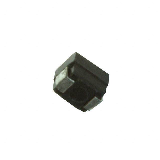
ICGOO在线商城 > 电感器,线圈,扼流圈 > 固定值电感器 > L06031R5CGSTR
- 型号: L06031R5CGSTR
- 制造商: AVX
- 库位|库存: xxxx|xxxx
- 要求:
| 数量阶梯 | 香港交货 | 国内含税 |
| +xxxx | $xxxx | ¥xxxx |
查看当月历史价格
查看今年历史价格
L06031R5CGSTR产品简介:
ICGOO电子元器件商城为您提供L06031R5CGSTR由AVX设计生产,在icgoo商城现货销售,并且可以通过原厂、代理商等渠道进行代购。 L06031R5CGSTR价格参考。AVXL06031R5CGSTR封装/规格:固定值电感器, 1.5nH Unshielded Thin Film Inductor 1A 60mOhm Max 0603 (1608 Metric) 。您可以下载L06031R5CGSTR参考资料、Datasheet数据手册功能说明书,资料中有L06031R5CGSTR 详细功能的应用电路图电压和使用方法及教程。
| 参数 | 数值 |
| 产品目录 | |
| DC电阻(DCR) | 80 毫欧最大 |
| 描述 | INDUCTOR THIN FILM 1.5NH 0603固定电感器 1.5nH |
| 产品分类 | |
| 品牌 | AVX |
| 产品手册 | |
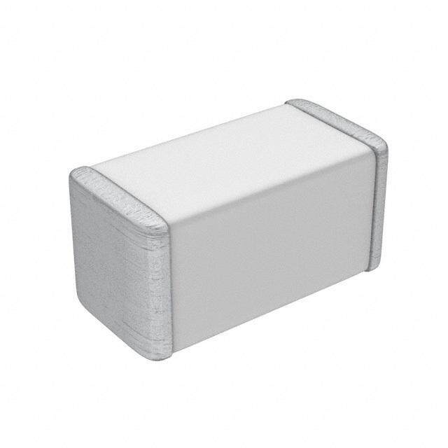
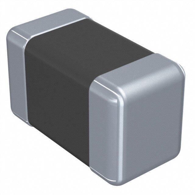
| 产品图片 |
|
| rohs | 符合RoHS无铅 / 符合限制有害物质指令(RoHS)规范要求 |
| 产品系列 | 固定电感器,AVX L06031R5CGSTRAccu-L® |
| 数据手册 | |
| 产品型号 | L06031R5CGSTR |
| Q最小值 | 26 |
| 不同频率时的Q值 | 26 @ 450MHz |
| 产品 | RF Inductors |
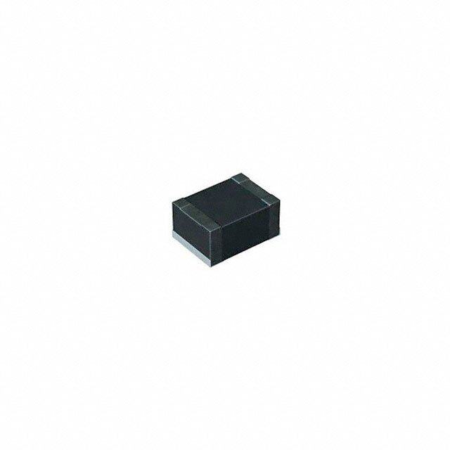
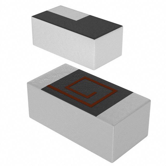
| 产品目录绘图 |
|
| 产品目录页面 | |
| 产品种类 | 固定电感器 |
| 供应商器件封装 | 0603(1608 Metric) |
| 其它名称 | 478-4325-6 |
| 包装 | Digi-Reel® |
| 商标 | AVX |
| 商标名 | Accu-L |
| 外壳宽度 | 0.81 mm |
| 外壳长度 | 1.6 mm |
| 外壳高度 | 0.61 mm |
| 大小/尺寸 | 0.063" 长 x 0.032" 宽(1.60mm x 0.81mm) |
| 安装类型 | 表面贴装 |
| 容差 | 0.2 nH |
| 封装 | Reel |
| 封装/外壳 | 0603(1608 公制) |
| 封装/箱体 | 0603 (1608 metric) |
| 屏蔽 | Unshielded |
| 工作温度 | -55°C ~ 125°C |
| 工作温度范围 | - 55 C to + 125 C |
| 工具箱 | /product-detail/zh/ACCU-L%20TYPE%201600%20LF/478-4323-ND/1531797 |
| 工厂包装数量 | 3000 |
| 最大直流电流 | 1 A |
| 最大直流电阻 | 60 mOhms |
| 材料-磁芯 | - |
| 标准包装 | 1 |
| 测试频率 | 450 MHz |
| 电感 | 1.5 nH |
| 电流-饱和值 | - |
| 端接类型 | SMD/SMT |
| 类型 | SMD High-Q RF Inductor |
| 系列 | Accu-L 0603 and 0805 |
| 自谐振频率 | 10000 MHz |
| 频率-测试 | 450MHz |
| 频率-自谐振 | 10GHz |
| 额定电流 | 1A |
| 高度-安装(最大值) | 0.028" (0.71mm) |




- 商务部:美国ITC正式对集成电路等产品启动337调查
- 曝三星4nm工艺存在良率问题 高通将骁龙8 Gen1或转产台积电
- 太阳诱电将投资9.5亿元在常州建新厂生产MLCC 预计2023年完工
- 英特尔发布欧洲新工厂建设计划 深化IDM 2.0 战略
- 台积电先进制程称霸业界 有大客户加持明年业绩稳了
- 达到5530亿美元!SIA预计今年全球半导体销售额将创下新高
- 英特尔拟将自动驾驶子公司Mobileye上市 估值或超500亿美元
- 三星加码芯片和SET,合并消费电子和移动部门,撤换高东真等 CEO
- 三星电子宣布重大人事变动 还合并消费电子和移动部门
- 海关总署:前11个月进口集成电路产品价值2.52万亿元 增长14.8%
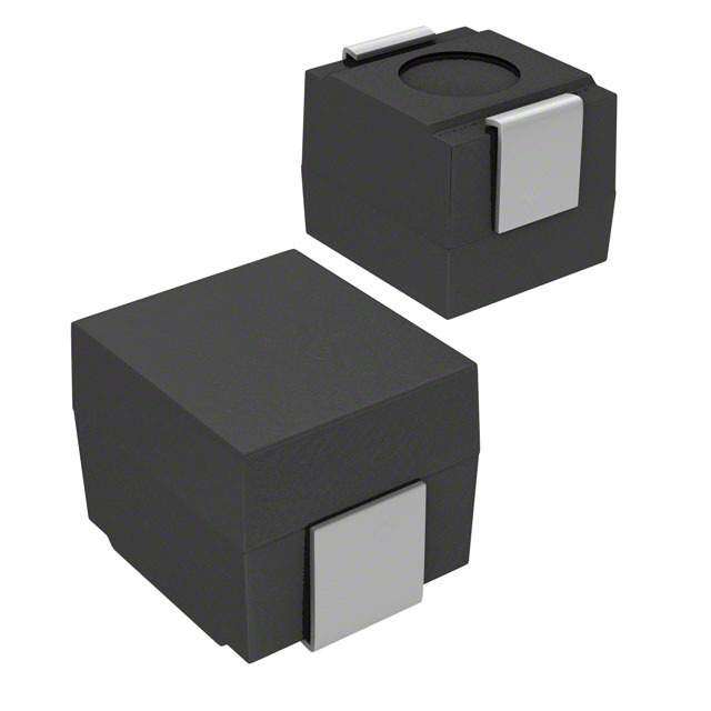
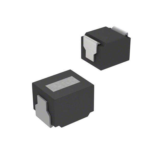
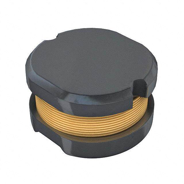
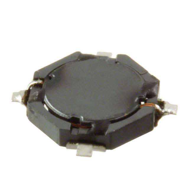

PDF Datasheet 数据手册内容提取
Accu-L® SMD High-Q RF Inductor 2 10 nH Inductor (Top View) ACCU-L® TECHNOLOGY The Accu-L® SMD Inductor is based on thin-film mul ti laye r The Accu-L® inductor is particularly suited for the telec om - technology. This technology provides a level of control on the mu ni ca tions industry where there is a continuing trend elect ri cal and physical characteristics of the comp o nent which towards miniaturization and inc reasi ng frequencies. The gives consistent characteristics within a lot and lot-to-lot. Accu-L®inductor meets both the perf orm ance and tolerance The original design provides small size, excellent high- requirements of present cellular frequencies 450MHz and frequency performance and rugged construction for rel i able 900MHz and of future freq uen cies, such as 1700MHz, automatic assembly. 1900MHz and 2400MHz. FEATURES APPLICATIONS • High Q • Mobile Communications • RF Power Capability • Satellite TV Receivers • High SRF • GPS • Low DC Resistance • Vehicle Locations Systems • Ultra-Tight Tolerance on Inductance • Filters • Standard 0603 and 0805 Chip Size • Matching Networks • Low Profile • Rugged Construction • Taped and Reeled DIMENSIONS: millimeters (inches) 0603 0805 Operating/Storage B 1.6±0.10 2.11±0.10 Temp. Range: L (0.063±0.004) (0.083±0.004) -55°C to +125°C 0.81±0.10 1.5±0.10 W (0.032±0.004) (0.059±0.004) W 0.61±0.10 0.91±0.13 T (0.024±0.004) (0.036±0.005) T top: 0.0 +0.3/-0.0 0.25±0.15 (0.0+0.012) (0.010±0.006) L B bottom: 0.35±0.20 (0.014±0.008) 36
Accu-L® 0603 and 0805 SMD High-Q RF Inductor HOW TO ORDER L 0805 4R7 D E S TR Product Size Inductance Tolerance Specification Termination Packaging Inductor 0603 Expressed in nH for Code Code Code 0805 (2 significant digits + L ≤4.7nH, E = Accu-L®0805 W = N ickel/ TR = Tape and Reel number of zeros) B = ±0.1nH technology solder coated (3,000/reel) for C = ±0.2nH G= Accu-L®0603 (Sn 63, Pb 37) values <10nH, D = ±0.5nH technology **S = Nickel/ letter R denotes Lead Free decimal point. 4.7nH<L<10nH, Solder coated Not RoHS Compliant Example: C =±0.2nH (Sn100) 22nH = 220 D = ±0.5nH 4.7nH = 4R7 **RoHS compliant 2 L ≥ 10nH, G = ±2% J = ±5% Engineering Kits Available LEAD-FREE COMPATIBLE COMPONENT see pages 114-115 For RoHS compliant products, please select correct termination style. ELECTRICAL SPECIFICATIONS TABLE FOR ACCU-L® 0603 450 MHz 900 MHz 1900 MHz 2400 MHz IDCmax Test Frequency Test Frequency Test Frequency Test Frequency (mA) Inductance Available Q L (nH) Q L (nH) Q L (nH) Q S(RMFH mz)in RDC(Ωm)ax L (nH) Inductance Tolerance Typical Typical Typical Typical (1) 1.2 ±0.1, ±0.2nH 49 1.2 70 1.2 134 1.2 170 10000 0.04 1000 1.5 ±0.1, ±0.2nH 26 1.54 39 1.52 63 1.52 76 10000 0.06 1000 1.8 ±0.1, ±0.2nH 20 1.74 30 1.73 50 1.72 59 10000 0.07 1000 2.2 ±0.1, ±0.2nH 20 2.2 30 2.24 49 2.24 56 10000 0.08 1000 2.7 ±0.1, ±0.2nH 21 2.7 30 2.75 48 2.79 54 9000 0.08 750 3.3 ±0.1, ±0.2, ±0.5nH 24 3.33 35 3.39 56 3.47 64 8400 0.08 750 3.9 ±0.1, ±0.2, ±0.5nH 25 3.9 57 4.06 60 4.21 69 6500 0.12 500 4.7 ±0.1, ±0.2, ±0.5nH 23 4.68 32 4.92 46 5.2 49 5500 0.15 500 5.6 ±0.2, ±0.5nH 26 5.65 36 5.94 54 6.23 60 5000 0.25 300 6.8 ±0.2, ±0.5nH 23 6.9 33 7.3 47 8.1 39 4500 0.30 300 8.2 ±0.2, ±0.5nH 23 8.4 31 10 35 12.1 31 3800 0.35 300 10.0 ±2%, ±5% 28 10 39 11.8 47 14.1 41 3500 0.45 300 12.0 ±2%, ±5% 28 13.2 38 14.1 30 17.2 20 3000 0.50 300 15.0 ±2%, ±5% 28 16.2 38 25.9 30 49.8 15 2500 0.60 300 (1)IDCmeasured for 15°C rise at 25°C ambient temperature when soldered to FR-4 board. Inductance and Q measured on Agilent 4291B / 4287 using the 16196A test fixture. ELECTRICAL SPECIFICATIONS TABLE FOR ACCU-L® 0805 450 MHz 900 MHz 1700 MHz 2400 MHz IDCmax Test Frequency Test Frequency Test Frequency Test Frequency (mA) Inductance Available Q L (nH) Q L (nH) Q L (nH) Q S(RMFH mz)in RD(CΩm)ax ΔT = 15°C ΔT = 70°C L (nH) Inductance Tolerance Typical Typical Typical Typical (1) (2) 1.2 ±0.1nH, ±0.2nH, ±0.5nH 60 1.2 92 1.2 122 1.2 92 10000 0.05 1000 2000 1.5 ±0.1nH, ±0.2nH, ±0.5nH 50 1.5 74 1.5 102 1.5 84 10000 0.05 1000 2000 1.8 ±0.1nH, ±0.2nH, ±0.5nH 50 1.8 72 1.8 88 1.9 73 10000 0.06 1000 2000 2.2 ±0.1nH, ±0.2nH, ±0.5nH 42 2.2 62 2.2 82 2.3 72 10000 0.07 1000 2000 2.7 ±0.1nH, ±0.2nH, ±0.5nH 42 2.7 62 2.8 80 2.9 70 10000 0.08 1000 2000 3.3 ±0.1nH, ±0.2nH, ±0.5nH 38 3.3 46 3.4 48 3.5 57 10000 0.11 750 1500 3.9 ±0.1nH, ±0.2nH, ±0.5nH 27 3.9 36 4.0 38 4.1 42 10000 0.20 750 1500 4.7 ±0.1nH, ±0.2nH, ±0.5nH 43 4.8 62 5.3 76 5.8 60 5500 0.10 750 1500 5.6 ±0.5nH 50 5.7 68 6.3 73 7.6 62 4600 0.10 750 1500 6.8 ±0.5nH 43 7.0 62 7.7 71 9.4 50 4500 0.11 750 1500 8.2 ±0.5nH 43 8.5 56 10.0 55 15.2 32 3500 0.12 750 1500 10 ±2%, ±5% 46 10.6 60 13.4 52 – – 2500 0.13 750 1500 12 ±2%, ±5% 40 12.9 50 17.3 40 – – 2400 0.20 750 1500 15 ±2%, ±5% 36 16.7 46 27 23 – – 2200 0.20 750 1000 18 ±2%, ±5% 30 21.9 27 – – – – 1700 0.35 500 1000 22 ±2%, ±5% 36 27.5 33 – – – – 1400 0.40 500 1000 (1) I measured for 15°C rise at 25°C ambient temperature L, Q, SRF measured on HP 4291A, Boonton 34A and Wiltron 360 DC (2) IDCmeasured for 70°C rise at 25°C ambient temperature Vector Analyzer, RDCmeasured on Keithley 580 micro-ohmmeter. 37
Accu-L® 0603 and 0805 SMD High-Q RF Inductor L0603 Typical Q vs. Frequency Typical Inductance vs. Frequency L0603 L0603 180 100 1.2nH 160 15nH 140 120 Q100 H) 8.2nH 8600 15..56nnHH L (n 10 6.8nH 4.7nH 40 3.3nH 8.2nH 20 2.2nH 15nH 1.8nH 0 1.2nH 2 0 1 2 3 10 0.5 1 1.5 2 2.5 3 Frequency (GHz) Frequency (GHz) Measured on AGILENT 4291B/4287 Measured on AGILENT 4291B/4287 using the 16196A test fixture using the 16196A test fixture L0805 Typical Q vs. Frequency Typical Inductance vs. Frequency L0805 L0805 140 100 120 1.2nH 100 1.5nH 22nH 80 H) Q 1.8nH nce (n 10 1150nnHH 60 5.6nH cta u nd 5.6nH 10nH I 40 15nH 20 1.8nH 22nH 1 0 0.01 0.1 1 10 0.1 1 10 Frequency (GHz) Frequency (GHz) Measured on HP4291A and Measured on HP4291A and Boonton 34A Coaxial Line Wiltron 360 Vector Analyzer Maximum Temperature Rise at 25°C ambient temperature (on FR-4) L0805 200 15nH 10nH 6.8nH4.7nH 2.7nH 100 °C) 10 T ( Δ 1 0 0.5 1 1.5 2 2.5 3 3.5 Current (A)(cid:1) Temperature rise will typically be no higher than shown by the graph 38
 Datasheet下载


