ICGOO在线商城 > IXFX15N100
- 型号: IXFX15N100
- 制造商: IXYS
- 库位|库存: xxxx|xxxx
- 要求:
| 数量阶梯 | 香港交货 | 国内含税 |
| +xxxx | $xxxx | ¥xxxx |
查看当月历史价格
查看今年历史价格
IXFX15N100产品简介:
ICGOO电子元器件商城为您提供IXFX15N100由IXYS设计生产,在icgoo商城现货销售,并且可以通过原厂、代理商等渠道进行代购。 提供IXFX15N100价格参考以及IXYSIXFX15N100封装/规格参数等产品信息。 你可以下载IXFX15N100参考资料、Datasheet数据手册功能说明书, 资料中有IXFX15N100详细功能的应用电路图电压和使用方法及教程。
| 参数 | 数值 |
| 产品目录 | |
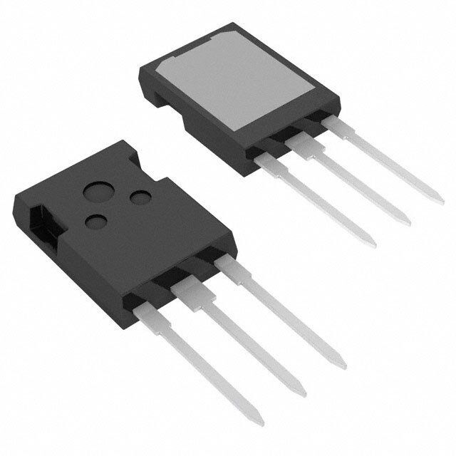
| 描述 | MOSFET N-CH 1KV 15A PLUS247 |
| 产品分类 | FET - 单 |
| FET功能 | 标准 |
| FET类型 | MOSFET N 通道,金属氧化物 |
| 品牌 | IXYS |
| 数据手册 | |
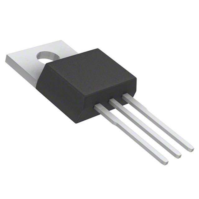
| 产品图片 |
|
| 产品型号 | IXFX15N100 |
| rohs | 无铅 / 符合限制有害物质指令(RoHS)规范要求 |
| 产品系列 | HiPerFET™ |
| 不同Id时的Vgs(th)(最大值) | 4.5V @ 4mA |
| 不同Vds时的输入电容(Ciss) | 4500pF @ 25V |
| 不同Vgs时的栅极电荷(Qg) | 220nC @ 10V |
| 不同 Id、Vgs时的 RdsOn(最大值) | 700 毫欧 @ 7.5A, 10V |
| 供应商器件封装 | PLUS247™-3 |
| 功率-最大值 | 360W |
| 包装 | 管件 |
| 安装类型 | 通孔 |
| 封装/外壳 | TO-247-3 |
| 标准包装 | 30 |
| 漏源极电压(Vdss) | 1000V(1kV) |
| 电流-连续漏极(Id)(25°C时) | 15A (Tc) |

PDF Datasheet 数据手册内容提取
HiPerFETTM V I R DSS D25 DS(on) Power MOSFETs IXFH/IXFT/IXFX14N100 1000 V 14 A 0.75 (cid:1) IXFH/IXFT/IXFX15N100 1000 V 15 A 0.70(cid:2)(cid:1) t (cid:3)(cid:2)200 ns N-Channel Enhancement Mode rr High dv/dt, Low t , HDMOSTM Family rr Preliminary data sheet E Symbol Test Conditions Maximum Ratings TO-247 AD (IXFH) V T = 25(cid:1)C to 150(cid:1)C 1000 V VDSS TJ = 25(cid:1)C to 150(cid:1)C; R = 1 M(cid:2) 1000 V T DGR J GS (TAB) V Continuous (cid:3)20 V VGS Transient (cid:3)30 V GSM E I T = 25(cid:1)C 14N100 14 A PLUS 247TM D25 C 15N100 15 A (IXFX) I T = 25(cid:1)C, pulse width limited by T 14N100 56 A DM C JM 15N100 60 A L I T = 25(cid:1)C 14N100 14 A AR C 15N100 15 A (TAB) G E T = 25(cid:1)C O 45 mJ D AR C dv/dt I (cid:4) I , di/dt (cid:4) 100 A/(cid:5)s, V (cid:4) V , 5 V/ns TO-268 (D3) TS (cid:4) 1D5M0(cid:1)C, R = 2 (cid:2) DD DSS (IXFT) J G P T = 25(cid:1)C 360 W G D C S (TAB) T -55 ... +150 (cid:1)C S J T 150 (cid:1)C TJM -55 ... +150 (cid:1)C Features stg B (cid:1) International standard packages T 1.6 mm (0.062 in.) from case for 10 s 300 (cid:1)C (cid:1) Low R HDMOSTM process L (cid:1) RuggeDdS p(oon)lysilicon gate cell structure M Mounting torque 1.13/10 Nm/lb.in. (cid:1) Unclamped Inductive Switching (UIS) d Weight O 6 g rated (cid:1) Low package inductance - easy to drive and to protect (cid:1) Fast intrinsic Rectifier Symbol Test Conditions Characteristic Values Applications (T = 25(cid:1)C, unless otherwise specified) (cid:1) DC-DC converters J min. typ. max. (cid:1) Battery chargers (cid:1) Switched-mode and resonant-mode V V = 0 V, I = 1 mA 1000 V power supplies DSS GS D V V = V , I = 4 mA 2.5 4.5 V (cid:1) DC choppers GS(th) DS GS D (cid:1) AC motor control I V = (cid:3)20 V , V = 0 (cid:3)100 nA (cid:1) Temperature and lighting controls GSS GS DC DS I V = 0.8 • V T = 25(cid:1)C 250 (cid:5)A Advantages DSS VDS = 0 V DSS TJ = 125(cid:1)C 1 mA (cid:1) Easy to mount with 1 screw (TO-247) GS J (isolated mounting screw hole) or R V = 10 V, I = 0.5 (cid:127)I 14N100 0.75 (cid:2) DS(on) GS D D25 15N100 0.70 (cid:2) mounting clip or spring (PLUS 247TM) (cid:1) High power surface mountable package Pulse test, t (cid:4) 300 (cid:5)s, duty cycle d(cid:6)(cid:4) 2 % (cid:1) High power density IXYS reserves the right to change limits, test conditions, and dimensions. 97535B (1/99) © 2000 IXYS All rights reserved 1 - 4
IXFH14N100 IXFT14N100 IXFX15N100 IXFH15N100 IXFT15N100 IXFX14N100 Symbol Test Conditions Characteristic Values TO-247 AD (IXFH) Outline (T = 25(cid:1)C, unless otherwise specified) J min. typ. max. g V = 10 V; I = 0.5 (cid:127)I , pulse test 6 10 S fs DS D D25 C 4500 pF iss C V = 0 V, V = 25 V, f = 1 MHz 430 pF oss GS DS C 150 pF rss t 27 ns d(on) t V = 10 V, V = 0.5 (cid:127)V , I = 0.5 (cid:127)I 30 ns Dim. Millimeter Inches tr RGS = 2(cid:6)(cid:2) (ExteDrSnal), DSS D D25 120 ns Min. Max. Min. Max. d(off) G t 30 ns A 1E9.8120.32 0.780 0.800 f B 20.8021.46 0.819 0.845 Q 220 nC C 15.7516.26 0.610 0.640 g(on) D 3.55 3.65 0.140 0.144 Q V = 10 V, V = 0.5 (cid:127)V , I = 0.5 (cid:127)I 30 nC Qgs GS DS DSS D D25 85 nC TE 4.32 5.49 0.170 0.216 gd F 5.4 6.2 0.212 0.244 R 0.35 K/W G 1.65 2.13 0.065 0.084 thJC H - 4.5 - 0.177 R 0.25 K/W thCK (TO-247 Case Style) E J 1.0 1.4 0.040 0.055 K 10.8 11.0 0.426 0.433 L 4.7 5.3 0.185 0.209 M 0.4 0.8 0.016 0.031 N 1.5 2.49 0.087 0.102 Source-Drain Diode CharaLcteristic Values (T = 25(cid:1)C, unless otherwise specified) PLUS247TM (IXFX) Outline J Symbol Test Conditions min. typ. max. O I V = 0 V 14N100 14 A S GS 15N100 15 A I Repetitive; 14N100 56 A SM pulse width limited by T S15N100 60 A JM V I = I , V = 0 V, 1.5 V SD PFulseS tesGSt, t (cid:4)(cid:6)300 (cid:5)s, duty cycle d(cid:6)(cid:4) 2 % B t T = 25(cid:1)C 200 ns rr I = I TJ = 125(cid:1)C 350 ns Dim. MiMn.illimMetaexr. MiInn.chMesax. Q -Fdi/dtS = 100 A/(cid:5)s, TJ = 25(cid:1)C 1 (cid:5)C A 4.83 5.21 .190 .205 I RM VR = 1O00 V TTJJ == 12255(cid:1)(cid:1)CC 102 (cid:5)AC AA12 21..2991 22..5146 ..009705 ..100805 RM TJ = 125(cid:1)C 15 A b 1.14 1.40 .045 .055 J b 1.91 2.13 .075 .084 1 b 2.92 3.12 .115 .123 2 C 0.61 0.80 .024 .031 D 20.80 21.34 .819 .840 TO-268AA (D3 PAK) E 15.75 16.13 .620 .635 Dim. Millimeter Inches e 5.45 BSC .215 BSC Min. Max. Min. Max. L 19.81 20.32 .780 .800 A 4.9 5.1 .193 .201 L1 3.81 4.32 .150 .170 A 2.7 2.9 .106 .114 1 Q 5.59 6.20 .220 .244 A .02 .25 .001 .010 2 R 4.32 4.83 .170 .190 b 1.15 1.45 .045 .057 b 1.9 2.1 .75 .83 2 Min. Recommended Footprint C .4 .65 .016 .026 D 13.80 14.00 .543 .551 E 15.85 16.05 .624 .632 E 13.3 13.6 .524 .535 1 e 5.45 BSC .215 BSC H 18.70 19.10 .736 .752 L 2.40 2.70 .094 .106 L1 1.20 1.40 .047 .055 L2 1.00 1.15 .039 .045 L3 0.25 BSC .010 BSC L4 3.80 4.10 .150 .161 © 2000 IXYS All rights reserved IXYS MOSFETS and IGBTs are covered by one or more of the following U.S. patents: 2 - 4 4,835,592 4,881,106 5,017,508 5,049,961 5,187,117 5,486,715 4,850,072 4,931,844 5,034,796 5,063,307 5,237,481 5,381,025
IXFH14N100 IXFT14N100 IXFX15N100 IXFH15N100 IXFT15N100 IXFX14N100 20 16 TJ = 25OC VGS = 9V TJ = 125OC V G S = 98VV 16 8V 7V 5V 7V 5V 12 6V 6V s s e e er 12 er p p m m 8 A A 4V - D 8 - D I 4V I 4 4 0 0 E 0 4 8 12 16 20 0 4 8 12 16 20 V - Volts V - Volts DS DS T Fig.1 Output Characteristics Fig.2 Output characteristics at elevated temperature 2.0 2E.2 1.8 VGS = 10V TJ = 125OC 2.0 VGS = 10V d d e e aliz 1.6 Laliz 1.8 m m Nor 1.4 Nor 1.6 ID = 15A R - DS(ON) 1.2 TJ = 25OC O R - DS(ON) 1.4 ID = 7.5A 1.0 1.2 S 0.8 1.0 0 3 6 9 12 15 25 50 75 100 125 150 ID - AmBperes TJ - Degrees C Fig.3 R vs. Drain Current Fig.4 Temperature Dependence of Drain DS(on) to Source Resistance O 20 14 12 16 IXF_15N100 10 s s ere 12 IXF_14N100 ere 8 p p m m A A 6 I - D 8 I - D 4 TJ = 125oC 4 T = 25oC J 2 0 0 -50 -25 0 25 50 75 100 125 150 2.0 2.5 3.0 3.5 4.0 4.5 5.0 T - Degrees C V - Volts C GS Fig.5 Drain Current vs. Case Temperature Fig.6 Input admittance © 2000 IXYS All rights reserved 3 - 4
IXFH14N100 IXFT14N100 IXFX15N100 IXFH15N100 IXFT15N100 IXFX14N100 12 5000 10 VVDdSs ==3 50000VV Ciss IIDD ==3 70.A5A 2500 II ==1 100mmAA F f = 1MHz GG p s 8 - olt ce 1000 Coss V - VGS 46 pacitan 500 Crss a C 250 2 0 100 E 0 40 80 120 160 200 240 280 0 5 10 15 20 25 30 35 40 Gate Charge - nC V - Volts DS T Fig.7 Gate Charge Characteristic Curve Fig.8 Capacitance Curves E 40 32 L s re 24 e mp TJ = 125OC O A - 16 D I T = 25OC J 8 S 0 0.4 0.6 0.8 1.0B1.2 1.4 1.6 V - Volts SD Fig.9 Source current vs Source drain voltage. O 1 W K/ - C 0.1 J ) h t ( R Single pulse 0.01 10-3 10-2 10-1 100 101 Pulse Width - Seconds Fig.10 Transient Thermal Impedance © 2000 IXYS All rights reserved 4 - 4
 Datasheet下载





-60DP-0.5V(57).jpg)