- 型号: ISO150AU
- 制造商: Texas Instruments
- 库位|库存: xxxx|xxxx
- 要求:
| 数量阶梯 | 香港交货 | 国内含税 |
| +xxxx | $xxxx | ¥xxxx |
查看当月历史价格
查看今年历史价格
ISO150AU产品简介:
ICGOO电子元器件商城为您提供ISO150AU由Texas Instruments设计生产,在icgoo商城现货销售,并且可以通过原厂、代理商等渠道进行代购。 ISO150AU价格参考。Texas InstrumentsISO150AU封装/规格:数字隔离器, 通用 数字隔离器 1500Vrms 2 通道 80MBd 1.6kV/µs(标准) CMTI 28-SOIC(0.295",7.50mm 宽)12 引线。您可以下载ISO150AU参考资料、Datasheet数据手册功能说明书,资料中有ISO150AU 详细功能的应用电路图电压和使用方法及教程。
| 参数 | 数值 |
| 产品目录 | |
| ChannelType | 双向 |
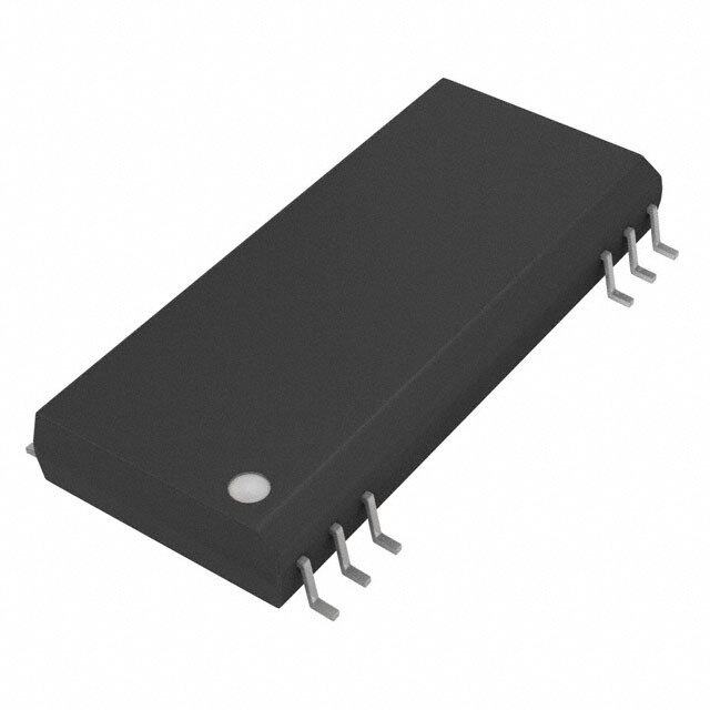
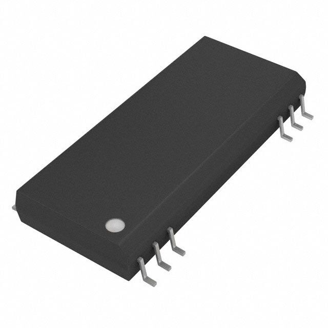
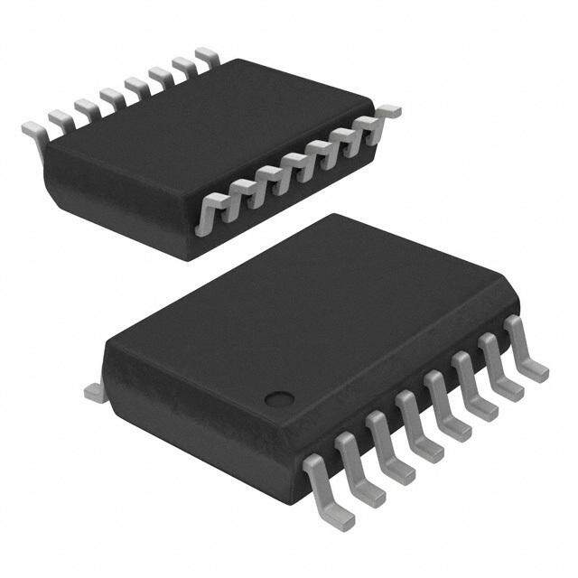
| 描述 | IC DGTL ISO 2CH CMOS 80MBD 12SOP数字隔离器 Dual Isol Bi-Dir Digital Coupler |
| 产品分类 | |
| IsolatedPower | 无 |
| 品牌 | Texas Instruments |
| 产品手册 | |
| 产品图片 |
|
| rohs | 符合RoHS无铅 / 符合限制有害物质指令(RoHS)规范要求 |
| 产品系列 | 接口 IC,数字隔离器,Texas Instruments ISO150AU- |
| 数据手册 | |
| 产品型号 | ISO150AU |
| PulseWidthDistortion(Max) | 6ns |
| 上升/下降时间(典型值) | 9ns, 9ns |
| 产品目录页面 | |
| 产品种类 | |
| 传播延迟tpLH/tpHL(最大值) | 40ns, 40ns |
| 传播延迟时间 | 40 ns |
| 供应商器件封装 | 12-SOP |
| 共模瞬态抗扰度(最小值) | 1.6kV/µs (标准) |
| 其它名称 | ISO150AUE4 |
| 制造商产品页 | http://www.ti.com/general/docs/suppproductinfo.tsp?distId=10&orderablePartNumber=ISO150AU |
| 包装 | 管件 |
| 反向通道 | 0 Channel |
| 商标 | Texas Instruments |
| 安装风格 | SMD/SMT |
| 封装 | Tube |
| 封装/外壳 | 28-SOIC(0.295",7.50mm 宽)12 引线 |
| 封装/箱体 | SOP-28-12 |
| 工作温度 | -40°C ~ 85°C |
| 工厂包装数量 | 20 |
| 技术 | 容性耦合 |
| 数据速率 | 80MBd |
| 最大工作温度 | + 85 C |
| 最大数据速率 | 80 Mb/s |
| 最小工作温度 | - 40 C |
| 标准包装 | 20 |
| 正向通道 | 2 Channel |
| 电压-电源 | 3 V ~ 5.5 V |
| 电压-隔离 | 1500Vrms |
| 电源电压-最大 | 5.5 V |
| 电源电压-最小 | 3 V |
| 电源电流 | 14 mA |
| 类型 | RS-485 |
| 系列 | ISO150 |
| 绝缘电压 | 1.5 kVrms |
| 脉宽失真(最大) | 6ns |
| 输入-输入侧1/输入侧2 | 2/2 |
| 通道数 | 2 |
| 通道数量 | 2 Channel |
| 通道类型 | 双向 |
| 隔离式电源 | 无 |


- 商务部:美国ITC正式对集成电路等产品启动337调查
- 曝三星4nm工艺存在良率问题 高通将骁龙8 Gen1或转产台积电
- 太阳诱电将投资9.5亿元在常州建新厂生产MLCC 预计2023年完工
- 英特尔发布欧洲新工厂建设计划 深化IDM 2.0 战略
- 台积电先进制程称霸业界 有大客户加持明年业绩稳了
- 达到5530亿美元!SIA预计今年全球半导体销售额将创下新高
- 英特尔拟将自动驾驶子公司Mobileye上市 估值或超500亿美元
- 三星加码芯片和SET,合并消费电子和移动部门,撤换高东真等 CEO
- 三星电子宣布重大人事变动 还合并消费电子和移动部门
- 海关总署:前11个月进口集成电路产品价值2.52万亿元 增长14.8%


PDF Datasheet 数据手册内容提取
ISO150 ISO150 www.ti.com.......................................................................................................................................... SBOS032D–SEPTEMBER2000–REVISEDAUGUST2008 DUAL, ISOLATED, BIDIRECTIONAL DIGITAL COUPLER FEATURES 1 • ReplacesHigh-PerformanceOptocouplers DESCRIPTION • DataRate:80MBaud,Typ The ISO150 is a 2-channel, galvanically-isolated data • LowPowerConsumption:25mWPerChannel, coupler capable of data rates of 80M Baud, typical. Each channel can be individually programmed to Max transmitdataineitherdirection. • TwoChannels,EachBidirectional, ProgrammablebyUser Data is transmitted across the isolation barrier by coupling complementary pulses through high voltage • PartialDischargeTested:2400Vrms 0.4 pF capacitors. Receiver circuitry restores the • CreepageDistanceof7,2mm pulses to standard logic levels. Differential signal • LowCostPerChannel transmission rejects isolation-mode voltage transients upto1.6kV/m s • AvailableinSOPackage • UL1577Certified The ISO150 avoids problems commonly associated with optocouplers. Optically isolated couplers require high current pulses and allowance must be made for APPLICATIONS LED aging. The ISO150's Bi-CMOS circuitry operates • DigitalIsolationforA/D,D/AConversion at25mWperchannel. • IsolatedRS-485Interface The ISO150 is available in an SO-28 and is specified • MultiplexedDataTransmission foroperationfrom–40°Cto85°C. • IsolatedParalleltoSerialInterface • TestEquipment • MicroprocessorSystemInterface • IsolatedLineReceiver • GroundLoopElimination 28 27 26 17 16 15 D2A R/T2A GA VSB R/T2B D2B Channel 2 Side A Side B Channel 1 D1A R/T1A VSA GB R/T1B D1B 1 2 3 12 13 14 1 Pleasebeawarethatanimportantnoticeconcerningavailability,standardwarranty,anduseincriticalapplicationsofTexas Instrumentssemiconductorproductsanddisclaimerstheretoappearsattheendofthisdatasheet. PRODUCTIONDATAinformationiscurrentasofpublicationdate. Copyright©2000–2008,TexasInstrumentsIncorporated Products conform to specifications per the terms of the Texas Instruments standard warranty. Production processing does not necessarilyincludetestingofallparameters.
ISO150 SBOS032D–SEPTEMBER2000–REVISEDAUGUST2008.......................................................................................................................................... www.ti.com This integrated circuit can be damaged by ESD. Texas Instruments recommends that all integrated circuits be handled with appropriateprecautions.Failuretoobserveproperhandlingandinstallationprocedurescancausedamage. ESDdamagecanrangefromsubtleperformancedegradationtocompletedevicefailure.Precisionintegratedcircuitsmaybemore susceptibletodamagebecauseverysmallparametricchangescouldcausethedevicenottomeetitspublishedspecifications. ORDERINGINFORMATION(1) SPECIFIED TRANSPORT PACKAGE PACKAGE PACKAGE ORDERING PRODUCT TEMPERATURE MEDIA, LEAD DESIGNATOR MARKING NUMBER RANGE QUANTITY ISO150AU Rails,28 ISO150AU SO-28 DVB –40°Cto85°C ISO150AU ISO150AU/1K TapeandReel,1000 (1) Forthemostcurrentpackageandorderinginformation,seethePackageOptionAddendumattheendofthisdocument,orseetheTI websiteatwww.ti.com. ABSOLUTE MAXIMUM RATINGS overoperatingfree-airtemperaturerange(unlessotherwisenoted)(1) (2) UNIT Storagetemperature –40°Cto125°C V Supplyvoltage –0.5Vto6V S V Transmitterinputvoltage –0.5VtoV +0.5V I S V Receiveroutputvoltage –0.5VtoV +0.5V O S R/T inputs –0.5VtoV +0.5V x S V IsolationvoltagedV/dt 500kV/m s ISO D Shorttoground Continuous x T Junctiontemperature 125°C J Leadtemperature(soldering,10s) 260°C (1) StressesbeyondthoselistedunderAbsoluteMaximumRatingsmaycausepermanentdamagetothedevice.Thesearestressratings onlyandfunctionaloperationofthedeviceattheseoranyotherconditionsbeyondthoseindicatedunderRecommendedOperating Conditionsisnotimplied.Exposuretoabsolutemaximumratedconditionsforextendedperiodsmayaffectdevicereliability. (2) Thisisolatorissuitableforbasicinsulationapplicationswithinthesafetylimitingdata.Maintenanceofthesafetydatamustbeensured bymeansofprotectivecircuitry. REGULATORY INFORMATION UL Recognizedunder1577ComponentRecognitionProgram(1) FileNumber:E181974 (1) Productiontestedat2400VRMSfor1secondinaccordancewithUL1577. 2 SubmitDocumentationFeedback Copyright©2000–2008,TexasInstrumentsIncorporated ProductFolderLink(s):ISO150
ISO150 www.ti.com.......................................................................................................................................... SBOS032D–SEPTEMBER2000–REVISEDAUGUST2008 ELECTRICAL CHARACTERISTICS AtT =25°CandV =5V(unlessotherwisenoted) A S ISO150AU PARAMETER TESTCONDITIONS UNIT MIN TYP MAX ISOLATIONPARAMETERS RatedVoltage,Continuous 60Hz 1500 Vrms PartialDischarge,100%Test(1) 1s,5pC 2400 Vrms Creepagedistance(external) SO-UPackage 7.2 mm Internalisolationdistance 0.10 mm Isolationvoltagetransientimmunity(2) 1.6 kV/m s Barrierimpedance >1014||7 Ω||pF Leakagecurrent 240Vrms,50Hz 0.6 m Arms DCPARAMETERS HIGH,V I =6mA V –1 V OH OH S S Logicoutputvoltage V LOW,V I =6mA 0 0.4 OL OL Logicoutputshort-circuitcurrent Sourceorsink 30 mA HIGH(3) 2 V S Logicinputvoltage V LOW(3) 0 0.8 Logicinputcapacitance 5 pF Logicinputcurrent <1 nA Power-supplyvoltagerange(3) 3 5 5.5 V DC 0.001 100 m A Transmitmode 50MBaud 14 mA Power-supplycurrent(4) DC 7.2 10 Receivemode mA 50MBaud 16 ACPARAMETERS Maximum(5) C =50pF 50 80 L Datarate MBaud Minimum DC Propagationtime(6) C =50pF 27 40 ns L Propagationdelayskew(7) C =50pF 0.5 2 ns L Pulsewidthdistortion(8) C =50pF 1.5 6 ns L Outputrise-and-falltime,10%to90% C =50pF 9 14 ns L ReceivetoTransmit 13 ns Modeswitchtime Transmittoreceive(9) 75 ns TEMPERATURERANGE Operatingrange –40 85 °C Storage –40 125 °C Thermalresistance,q 75 °C/W JA (1) Alldevicesreceivea1stest.Failurecriterionis≥5PULSESOF≥5Pc. (2) Thevoltagerate-of-changeacrosstheisolationbarrierthatcanbesustainedwithoutdataerrors. (3) LogicinputsareHCT-typeandthresholdsareafunctionofpower-supplyvoltagewithapproximately0.4Vhysteresis–seetext. (4) Supplycurrentmeasuredwithbothtransceiverssetfortheindicatedmode.Supplycurrentvarieswithdatarate–seetypical characteristics. (5) Calculatedfromthemaximumpulsewidthdistortion(PWD),whereDataRate=0.3/PWD. (6) PropagationtimemeasuredfromV =1.5VtoV =2.5V. IN O (7) ThedifferenceinpropagationtimeofchannelAandchannelBinanycombinationoftransmissiondirections. (8) Thedifferencebetweenpropagationtimeofarisingedgeandafallingedge. (9) Whenthedeviceispoweredupordirectionischanged,thetransceiveroutputisindeterminate(eitherhighorlow)andcannotbeknown untilaninputsignalisapplied.Theoutputbeginstotracktheinputassoonastheinputreceivesachangeinlogicstate,eitherlowto highorhightolow. Copyright©2000–2008,TexasInstrumentsIncorporated SubmitDocumentationFeedback 3 ProductFolderLink(s):ISO150
ISO150 SBOS032D–SEPTEMBER2000–REVISEDAUGUST2008.......................................................................................................................................... www.ti.com PIN CONFIGURATION Top View SO D1A 1 28 D2A R/T1A 2 27 R/T2A VSA 3 26 GA GB 12 17 VSB R/T1B 13 16 R/T2B D1B 14 15 D2B TERMINALFUNCTIONS TERMINAL DESCRIPTION NAME NO. D 1 Datainordataoutfortransceiver1A,R/T heldlowmakesD andinputpin. 1A 1A 1A R/T 2 Receive/transmitswitchcontrollingtransceiver1A. 1A V 3 +5VsupplypinforsideA,whichpowerstransceivers1Aand2A. SA G 12 Groundpinfortransceivers1Band2B. B R/T 13 Receive/transmitswitchcontrollingtransceiver1B. 1B D 14 Datainordataoutfortransceiver1B.R/T heldLOWmakesD aninputpin. 1B 1B 1B D 15 Datainordataoutfortransceiver2B.R/T heldLOWmakesD aninputpin. 2B 2B 2B R/T 16 Receive/transmitswitchcontrollingD . 2B 2B V 17 +5VsupplypinforsideB,whichpowerstransceivers1Band2B. SB G 26 Groundpinfortransceivers1Aand2A. A R/T 27 Receive/transmitswitchcontrollingtransceiver2A. 2A D 28 Datainordataoutfortransceiver2A,R/T heldlowmakesD aninputpin. 2A 21A 2A 4 SubmitDocumentationFeedback Copyright©2000–2008,TexasInstrumentsIncorporated ProductFolderLink(s):ISO150
ISO150 www.ti.com.......................................................................................................................................... SBOS032D–SEPTEMBER2000–REVISEDAUGUST2008 TYPICAL CHARACTERISTICS AtT =25°CandV =5V,unlessotherwisenoted. A S SUPPLYCURRENTPERCHANNELvsSUPPLYVOLTAGE POWERCONSUMPTIONPERCHANNELvsFREQUENCY 5 100 20 CL = 15pF No Load One Channel f = 1MHz = 2MBaud 4 80 16 Supply Current (mA) 32 Receive Mode Power (mW) 4600 NOTE: Baud Rate = 2 (cid:1) FrequenRceyceive 182Supply Current (mA) 1 20 Transmit 4 Transmit Mode 0 0 0 12345 6 100k 1M 10M 100M Frequency (Hz) Supply Voltage, V S (V) Figure1. Figure2. TYPICALRISEANDFALLTIMESvsCAPACITIVELOADvs SUPPLYCURRENTPERCHANNELvsTEMPERATURE SUPPLYVOLTAGE 6 100 tr 5 80 tf mA) VS= 5.0V ttfr y Current ( 43 t, t (ns)rf 6400 VS = 3.0V pl p u S 2 VS= 3.0V 20 VS = 5.0V 1 0 –60 –40 –20 0 20 40 60 80 100 120 140 0 100 200 300 400 500 Temperature ((cid:1)C) Capacitive Load (pF) Figure3. Figure4. NORMALIZEDRISE-AND-FALLTIMEvsTEMPERATURE PROPAGATIONDELAYvsSUPPLYVOLTAGE 1.6 45 1.5 CL = 50pF 40 1.4 +1s ns) HIGH to LOW , trf1.3 elay ( 35 Relative t 1.2 Noromf aMlizaeandty 2 tD5o° eAvCviceerasge agation D 30 1.1 op LOW to HIGH Pr 25 1.0 –1s Pulse Width Distortion .9 20 –60 –40 –20 0 20 40 60 80 100 120 140 2.5 3.0 3.5 4.0 4.5 5.0 5.5 Temperature ((cid:1)C) Supply Voltage, VS (V) Figure5. Figure6. Copyright©2000–2008,TexasInstrumentsIncorporated SubmitDocumentationFeedback 5 ProductFolderLink(s):ISO150
ISO150 SBOS032D–SEPTEMBER2000–REVISEDAUGUST2008.......................................................................................................................................... www.ti.com TYPICAL CHARACTERISTICS (continued) AtT =25°CandV =5V,unlessotherwisenoted. A S PROPAGATIONDELAYvsTEMPERATURE PULSEWIDTHDISTORTIONvsTEMPERATURE 60 5 CL = 50pF VS = 5.0 V pagation Delay, t (ns)PD 54320000 VVSS == 35..00VV Width Distortion, PWD (ns) 432 CL = 50 pF Pro 10 Pulse 1 0 0 –60 –40 –20 0 20 40 60 80 100 120 140 –60 –40 –20 0 20 40 60 80 100 120 140 Temperature ((cid:1)C) Temperature ((cid:1)C) Figure7. Figure8. LOGICINPUTTHRESHOLDVOLTAGEvsSUPPLY OUTPUTVOLTAGE VOLTAGE vsLOGICINPUTVOLTAGE 2.0 1.8 VT HIGH, 125°C 5 1.6 1.4 4 1.2 V) V (V)IN 1.0 VT LOW, –40°C V(OUT 3 0.8 2 0.6 0.4 1 0.2 0 2.0 2.5 3.0 3.5 4.0 4.5 5.0 5.5 6.0 0 0.5 1.0 1.5 2.0 Supply Voltage, VSS (V) VIN (V) Figure9. Figure10. ISOLATIONLEAKAGECURRENT vsFREQUENCY ISOLATIONVOLTAGEvsFREQUENCY 100m 2.1k Max DC Rating 10m ms) 1m e (V) 1k DPeergfroardmeadnce Ar ag Leakage Current ( 10100mm VISO = 1500Vrms VISO = 240Vrms Peak Isolation Volt 11000 1m 100n 1 1 10 100 1 k 10 k 100 k 1 M 1 k 10 k 100 k 1 M 10 M 100 M Frequency (Hz) Frequency (Hz) Figure11. Figure12. 6 SubmitDocumentationFeedback Copyright©2000–2008,TexasInstrumentsIncorporated ProductFolderLink(s):ISO150
ISO150 www.ti.com.......................................................................................................................................... SBOS032D–SEPTEMBER2000–REVISEDAUGUST2008 TYPICAL CHARACTERISTICS (continued) AtT =25°CandV =5V,unlessotherwisenoted. A S TYPICALINSULATIONRESISTANCE vsTEMPERATURE 1016 1015 We ( ) 1014 c n a sist 1013 e R n atio 1012 ol s I 1011 1010 0 20 40 60 80 100 120 140 160 180 Temperature ((cid:1)C) Figure13. produced by localized ionization within the barrier; ISOLATION BARRIER this is the most sensitive and reliable indicator of barrier integrity and longevity, and does not damage Data is transmitted by coupling complementary logic the barrier. A device fails the test if five or more pulses to the receiver through two 0.4 pF capacitors. currentpulsesof5pCorgreateraredetected. These capacitors are built into the ISO150 package with Faraday shielding to guard against false Conventional isolation barrier testing applies test triggeringbyexternalelectrostaticfields. voltage far in excess of the rated voltage to catastrophically break down a marginal device. A The integrity of the isolation barrier of the ISO150 is device that passes the test may be weakened, and verified by partial discharge testing: 2400 Vrms, 60 leadtoprematurefailure. Hz, is applied across the barrier for one second while measuring any tiny discharge currents that might flow through the barrier. These current pulses are Copyright©2000–2008,TexasInstrumentsIncorporated SubmitDocumentationFeedback 7 ProductFolderLink(s):ISO150
ISO150 SBOS032D–SEPTEMBER2000–REVISEDAUGUST2008.......................................................................................................................................... www.ti.com APPLICATION INFORMATION shown. The transmission direction can be controlled Figure 14 shows the ISO150 connected for basic by logic signals applied to the R/T pins. Channel 1 operation; Channel 1 is configured to transmit data and 2 can be independently controlled for the desired from side B to A, whereas Channel 2 is set for transmission direction. See Figure 15 and Figure 16 transmission from side A to B. The R/T pins for each forapplicationexamplesusingtheISO150. of the four transceivers are shown connected to the required logic level for the transmission direction (1) +5V (Transmit) (2) (Receive) Channel 2 Channel 2 Data In (1) (1) Data Out D2A R/T2A GA VSB R/T2B D2B Channel 2 NOTES: (1) Power Supplies and grounds on side A and side B are Side A Side B isolated. (2) Recommended bypass: 0.1(cid:1)F in parallel with 1nF. Channel 1 D1A R/T1A VSA GB R/T1B D1B Channel 1 (2) Channel 1 Data Out (Receive) (1) (1) (Transmit) Data In +5V(1) Figure14.BasicOperationDiagram +5V DE SN65HVD05 +5V A D Data BUS (I/O) B D2A R/T2A GA VSB R/T2B D2B Channel 2 R RE Side A Side B Channel 1 D1A R/T1A VSA GB R/T1B D1B DE/RE +5V ”1” (+5V) Figure15.IsolatedRS-485Interface 8 SubmitDocumentationFeedback Copyright©2000–2008,TexasInstrumentsIncorporated ProductFolderLink(s):ISO150
ISO150 www.ti.com.......................................................................................................................................... SBOS032D–SEPTEMBER2000–REVISEDAUGUST2008 Still, some applications with large, noisy isolation- LOGIC LEVELS mode voltage can produce data errors by causing the A single pin serves as a data input or output, receiver output to change states. After a data error, depending on the mode selected. Logic inputs are subsequentchangesininputdatawillproducecorrect CMOS with thresholds set for TTL compatibility. The outputdata. logic threshold is approximately 1.3 V with 5 V supplies with approximately 400 mV of hysteresis. PROPAGATION DELAY AND SKEW Input logic thresholds vary with the power-supply Logic transitions are delayed approximately 27ns voltage. Drive the logic inputs with signals that swing through the ISO150. Some applications are sensitive the full logic voltage swing, note that the ISO150 will to data skew—the difference in propagation delay use somewhat greater quiescent current if logic between channel 1 and channel 2. Skew is less than inputs do not swing within 0.5 V of the power-supply 2ns between channel 1 and channel 2. Applications rails. using more than one ISO150 must allow for In receive mode, the data output can drive 15 somewhat greater skew from device to device. As all standard LS-TTL loads. It will also drive CMOS loads. devices are tested for delay times of 20ns min to TheoutputdrivecircuitsareCMOS. 40ns max, 20ns is the largest device-to-device data skew. POWER SUPPLY MODE CHANGES Separate, isolated power supplies must be connected to side A and side B to provide galvanic isolation. The transmission direction of a channel can be Nominal rated supply voltage is 5 V. Operation changed on the fly by reversing the logic levels at the extends from 3 V to 5.5 V. Power supplies should be channel'sR/Tpin.Notethatwhenchanneldirection is bypassed close to the device pins on both sides of changed, the output state of the channel is theisolationbarrier. indeterminate (either high or low) and cannot be known until an input signal is applied. The output The V pin for each side powers the transceivers for S begins to track the input as soon as the input both channel 1 and 2. The specified supply current is receives a change in logic state, either low to high or the total of both transceivers on one side, both hightolow. operating in the indicated mode. Supply current for one transceiver in transmit mode and one in receive STANDBY MODE mode can be estimated by averaging the specifications for transmit and receive operation. Quiescent current of each transceiver circuit is very Supply current varies with the data transmission rate low in transmit mode when input data is not changing —seethetypicalcharacteristics. (1nA typical). To conserve power when data transmission is not required, program both side A and POWER-UP STATE B transceivers for transmit mode. Input data applied to either transceiver is ignored by the other side. When the device is powered up or direction is High-speed data applied to either transceiver will changed, the transceiver output is indeterminate increasequiescentcurrent. (either high or low) and cannot be known until an input signal is applied. The output begins to track the CIRCUIT LAYOUT input as soon as the input receives a change in logic state,eitherlowtohighorhightolow. The high speed of the ISO150 and its isolation barrier require careful circuit layout. Use good high speed SIGNAL LOSS logic layout techniques for the input and output data lines. Power supplies should be bypassed close to The ISO150's differential-mode signal transmission the device pins on both sides of the isolation barrier. and careful receiver design make it highly immune to Use low inductance connections. Ground planes are voltage across the isolation barrier (isolation-mode recommended. voltage). Rapidly changing isolation-mode voltage can cause data errors. As the rate of change of Maintain spacing between side 1 and side 2 circuitry isolation voltage is increased, there is a very sudden equal or greater than the spacing between the increase in data errors. Approximately 50% of all missingpinsoftheISO150(approximately7mm). ISO150s will begin to produce data errors with isolation-mode transients of 1.6kV/m s. This may occur as low as 500 V/m s in some devices. In comparison, a 1000 Vrms, 60 Hz isolation-mode voltage has a rateofchangeofapproximately0.5V/m s. Copyright©2000–2008,TexasInstrumentsIncorporated SubmitDocumentationFeedback 9 ProductFolderLink(s):ISO150
ISO150 SBOS032D–SEPTEMBER2000–REVISEDAUGUST2008.......................................................................................................................................... www.ti.com U2 15QASER 1QB 2QCSRCLK 3QDSRCLR 4QE 5QFRCLK 6QGG 7QH 9QH74LS595 High Byte EnableC2Low Byte EnableU315QASER 1QB 2SRCLKQC 3SRCLRQD 4QE 5QFRCLK 6QGG 7QH 9QH74LS595 C 4 1 0 2 3 V 4 1 0 2 3 1 1 1 1 1 1 1 1 1 1 Y S U B D2B D1B D2B D1B VR/TSB2B GR/TB1B R/C VR/TSB2B GR/TB1B +5VVCC2 V 5 + +5VVCC2 50 50 1 1 O O IS +5VVCC1 IS +5VVCC1 +5VVCC1 GR/TA2A R/TVSA1A GR/TA2A R/TVSA1A D2A D1A D2A D1A W1 W1 m10F m6.8F F F n n 0 0 10 10 W100 W100 YTE W100 W100 B 28 27 24 22 21 17 16 15 13 12 11 10 9 14 19 18 07 VDIG VANA BUSY R/C BYTE D0 D1 D2 D3 D4 D5 D6 D7 DGND SDATA SCLK 8 7 ADS R1IN R2IN AGND1 CAP REF AGND2 SB/BTC EXT/INT PWRD REFD CS TAG 1 3 2 4 F 5 F 6 7 8 25 26 23 20 m+2.2 m+2.2 Vs W200 = +5C2Supplie W33.2 W1M = VC1Colated W100 W50k VCIs Wk 0 C1 5 C V N VI Figure16.TheISO150andtheADS7807areUsedtoReduceCircuitNoiseinaMixed-SignalApplication 10 SubmitDocumentationFeedback Copyright©2000–2008,TexasInstrumentsIncorporated ProductFolderLink(s):ISO150
ISO150 www.ti.com.......................................................................................................................................... SBOS032D–SEPTEMBER2000–REVISEDAUGUST2008 Revision History ChangesfromOriginal(August1994)toRevisionA ..................................................................................................... Page • ChangedFeaturesBullet-From:PlasticDIPandSOICPackagesTo:AvailableinSOPackage....................................... 1 • ChangedFrom:ISO150isavailableina24-pinDIPpackageTo:TheISO150isavailableinanSO-28............................ 1 • ChangedFromBurr-BrownTo:Burr-BrownProductsfromTexasInstruments(Newlayout)............................................... 1 • DeletedtheDIPPackagefromtheOrderingInformationTable............................................................................................ 2 • DeletedDIP-PPackagefromCreepagedistance(external)intheElectricalCharacteristicsTable..................................... 3 • DeletedDIP-PPackageillustrationfromthePinConfiguration............................................................................................. 4 • ChangedPinConfigurationFrom:SOICPackageTo:SOPackage..................................................................................... 4 • ChangedCircuitLayoutparagraphFrom:ISO150(approximately16mmfortheDIPversion).Socketsarenot recommended.To:ISO150(approximately7mm)................................................................................................................. 9 ChangesfromRevisionA(February2003)toRevisionB ............................................................................................. Page • ChangedFormatandlayout.................................................................................................................................................. 1 • AddedNote9totheElectricalCharacteristicsTable............................................................................................................ 3 ChangesfromRevisionB(February2005)toRevisionC ............................................................................................. Page • AddedFeature:UL1577Certified......................................................................................................................................... 1 • AddedTable:RegulatoryInformation.................................................................................................................................... 2 ChangesfromRevisionC(October2007)toRevisionD ............................................................................................... Page • ChangedAbsMaxTable-JunctionTemperatureFrom:175°Cto125°C............................................................................ 2 Copyright©2000–2008,TexasInstrumentsIncorporated SubmitDocumentationFeedback 11 ProductFolderLink(s):ISO150
PACKAGE OPTION ADDENDUM www.ti.com 3-Nov-2016 PACKAGING INFORMATION Orderable Device Status Package Type Package Pins Package Eco Plan Lead/Ball Finish MSL Peak Temp Op Temp (°C) Device Marking Samples (1) Drawing Qty (2) (6) (3) (4/5) ISO150AP OBSOLETE PDIP NVG 12 TBD Call TI Call TI ISO150AU-1 OBSOLETE SOIC DVA 8 TBD Call TI Call TI (1) The marketing status values are defined as follows: ACTIVE: Product device recommended for new designs. LIFEBUY: TI has announced that the device will be discontinued, and a lifetime-buy period is in effect. NRND: Not recommended for new designs. Device is in production to support existing customers, but TI does not recommend using this part in a new design. PREVIEW: Device has been announced but is not in production. Samples may or may not be available. OBSOLETE: TI has discontinued the production of the device. (2) Eco Plan - The planned eco-friendly classification: Pb-Free (RoHS), Pb-Free (RoHS Exempt), or Green (RoHS & no Sb/Br) - please check http://www.ti.com/productcontent for the latest availability information and additional product content details. TBD: The Pb-Free/Green conversion plan has not been defined. Pb-Free (RoHS): TI's terms "Lead-Free" or "Pb-Free" mean semiconductor products that are compatible with the current RoHS requirements for all 6 substances, including the requirement that lead not exceed 0.1% by weight in homogeneous materials. Where designed to be soldered at high temperatures, TI Pb-Free products are suitable for use in specified lead-free processes. Pb-Free (RoHS Exempt): This component has a RoHS exemption for either 1) lead-based flip-chip solder bumps used between the die and package, or 2) lead-based die adhesive used between the die and leadframe. The component is otherwise considered Pb-Free (RoHS compatible) as defined above. Green (RoHS & no Sb/Br): TI defines "Green" to mean Pb-Free (RoHS compatible), and free of Bromine (Br) and Antimony (Sb) based flame retardants (Br or Sb do not exceed 0.1% by weight in homogeneous material) (3) MSL, Peak Temp. - The Moisture Sensitivity Level rating according to the JEDEC industry standard classifications, and peak solder temperature. (4) There may be additional marking, which relates to the logo, the lot trace code information, or the environmental category on the device. (5) Multiple Device Markings will be inside parentheses. Only one Device Marking contained in parentheses and separated by a "~" will appear on a device. If a line is indented then it is a continuation of the previous line and the two combined represent the entire Device Marking for that device. (6) Lead/Ball Finish - Orderable Devices may have multiple material finish options. Finish options are separated by a vertical ruled line. Lead/Ball Finish values may wrap to two lines if the finish value exceeds the maximum column width. Important Information and Disclaimer:The information provided on this page represents TI's knowledge and belief as of the date that it is provided. TI bases its knowledge and belief on information provided by third parties, and makes no representation or warranty as to the accuracy of such information. Efforts are underway to better integrate information from third parties. TI has taken and continues to take reasonable steps to provide representative and accurate information but may not have conducted destructive testing or chemical analysis on incoming materials and chemicals. TI and TI suppliers consider certain information to be proprietary, and thus CAS numbers and other limited information may not be available for release. In no event shall TI's liability arising out of such information exceed the total purchase price of the TI part(s) at issue in this document sold by TI to Customer on an annual basis. Addendum-Page 1
PACKAGE OPTION ADDENDUM www.ti.com 3-Nov-2016 Addendum-Page 2
MECHANICAL DATA MPDI068 – AUGUST 2001 NVG (R-PDIP-T12/24) PLASTIC DUAL-IN-LINE D 1.195 (30,35) 1.160 (29,46) 24 13 0.280 (7,11) D 0.240 (6,10) 1 0.655 (16,64) 12 Index 0.630 (16,00) Area 0.195 (4,95) 0.115 (2,92) 0.070 (1,78) 0.210 (5,33) 0.325 (8,26) Base Plane H E 0.045 (1,14) MAX 0.300 (7,62) C –C– Seating Plane E 0.150 (3,81) 0.300 (7,62) 0.005 (0,13) MIN 0.100 (2,54) 0.115 (2,92) C 1/2 Lead 4 PL D 0.014 (0,36) 0.022 (0,56) 0.015 (0,38) 0.008 (0,20) 0.045 (1,14) 4 PL 0.014 (0,36) MINC 0.060 (1,52) 0.030 (0,76) H 0.010 (0,25) M C 0.000 (0,00) F 0.430 (10,92) MAX F 4202644/A 08/01 NOTES: A. All linear dimensions are in inches (millimeters). I. Distance between leads including dambar protrusions B. This drawing is subject to change without notice. to be 0.005 (0,13) minimum. J. A visual index feature must be located within the C. Dimensions are measured with the package cross–hatched area. seated in JEDEC seating plane gauge GS-3. K. For automatic insertion, any raised irregularity on the D. Dimensions do not include mold flash or protrusions. top surface (step, mesa, etc.) shall be symmetrical Mold flash or protrusions shall not exceed 0.010 (0,25). E. Dimensions measured with the leads constrained to be about the lateral and longitudinal package centerlines. perpendicular to Datum C. L. Controlling dimension in inches. M. Falls within JEDEC-MS-001-BE with exception of lead F. Dimensions are measured at the lead tips with the count. leads unconstrained. G. Pointed or rounded lead tips are preferred to ease insertion. H. Maximum dimensions do not include dambar protrusions. Dambar protrusions shall not exceed 0.010 (0,25). POST OFFICE BOX 655303 • DALLAS, TEXAS 75265 1
MECHANICAL DATA MPDS105 – AUGUST 2001 DVA (R-PDSO-G8/28) PLASTIC SMALL-OUTLINE C A 18,10 0,25 M B M 17,70 28 15 B 7,60 10,65 7,40 10,01 D Index Area 1 14 2,65 0,75 x 45° 2,35 0,25 C Seating Plane 0,51 0,10 0,32 1,27 0,30 G 0,33 0,23 0,10 0,25 M C A M B S 0°–8° 1,27 0,40 F 4202103/B 08/01 NOTES: A. All linear dimensions are in millimeters. G. Lead width, as measured 0,36 mm or greater B. This drawing is subject to change without notice. above the seating plane, shall not exceed a maximum value of 0,61 mm. C. Body length dimension does not include mold H. Lead-to-lead coplanarity shall be less than flash, protrusions, or gate burrs. Mold flash, protrusions, 0,10 mm from seating plane. and gate burrs shall not exceed 0,15 mm per side. I. Falls within JEDEC MS-013-AE with the exception D. Body width dimension does not include inter-lead flash or portrusions. Inter-lead flash and protrusions of the number of leads. shall not exceed 0,25 mm per side. E. The chamfer on the body is optional. If it is not present, a visual index feature must be located within the cross-hatched area. F. Lead dimension is the length of terminal for soldering to a substrate. POST OFFICE BOX 655303 • DALLAS, TEXAS 75265 1
IMPORTANTNOTICE TexasInstrumentsIncorporatedanditssubsidiaries(TI)reservetherighttomakecorrections,enhancements,improvementsandother changestoitssemiconductorproductsandservicesperJESD46,latestissue,andtodiscontinueanyproductorserviceperJESD48,latest issue.Buyersshouldobtainthelatestrelevantinformationbeforeplacingordersandshouldverifythatsuchinformationiscurrentand complete.Allsemiconductorproducts(alsoreferredtohereinas“components”)aresoldsubjecttoTI’stermsandconditionsofsale suppliedatthetimeoforderacknowledgment. TIwarrantsperformanceofitscomponentstothespecificationsapplicableatthetimeofsale,inaccordancewiththewarrantyinTI’sterms andconditionsofsaleofsemiconductorproducts.TestingandotherqualitycontroltechniquesareusedtotheextentTIdeemsnecessary tosupportthiswarranty.Exceptwheremandatedbyapplicablelaw,testingofallparametersofeachcomponentisnotnecessarily performed. TIassumesnoliabilityforapplicationsassistanceorthedesignofBuyers’products.Buyersareresponsiblefortheirproductsand applicationsusingTIcomponents.TominimizetherisksassociatedwithBuyers’productsandapplications,Buyersshouldprovide adequatedesignandoperatingsafeguards. TIdoesnotwarrantorrepresentthatanylicense,eitherexpressorimplied,isgrantedunderanypatentright,copyright,maskworkright,or otherintellectualpropertyrightrelatingtoanycombination,machine,orprocessinwhichTIcomponentsorservicesareused.Information publishedbyTIregardingthird-partyproductsorservicesdoesnotconstitutealicensetousesuchproductsorservicesorawarrantyor endorsementthereof.Useofsuchinformationmayrequirealicensefromathirdpartyunderthepatentsorotherintellectualpropertyofthe thirdparty,oralicensefromTIunderthepatentsorotherintellectualpropertyofTI. ReproductionofsignificantportionsofTIinformationinTIdatabooksordatasheetsispermissibleonlyifreproductioniswithoutalteration andisaccompaniedbyallassociatedwarranties,conditions,limitations,andnotices.TIisnotresponsibleorliableforsuchaltered documentation.Informationofthirdpartiesmaybesubjecttoadditionalrestrictions. ResaleofTIcomponentsorserviceswithstatementsdifferentfromorbeyondtheparametersstatedbyTIforthatcomponentorservice voidsallexpressandanyimpliedwarrantiesfortheassociatedTIcomponentorserviceandisanunfairanddeceptivebusinesspractice. TIisnotresponsibleorliableforanysuchstatements. Buyeracknowledgesandagreesthatitissolelyresponsibleforcompliancewithalllegal,regulatoryandsafety-relatedrequirements concerningitsproducts,andanyuseofTIcomponentsinitsapplications,notwithstandinganyapplications-relatedinformationorsupport thatmaybeprovidedbyTI.Buyerrepresentsandagreesthatithasallthenecessaryexpertisetocreateandimplementsafeguardswhich anticipatedangerousconsequencesoffailures,monitorfailuresandtheirconsequences,lessenthelikelihoodoffailuresthatmightcause harmandtakeappropriateremedialactions.BuyerwillfullyindemnifyTIanditsrepresentativesagainstanydamagesarisingoutoftheuse ofanyTIcomponentsinsafety-criticalapplications. Insomecases,TIcomponentsmaybepromotedspecificallytofacilitatesafety-relatedapplications.Withsuchcomponents,TI’sgoalisto helpenablecustomerstodesignandcreatetheirownend-productsolutionsthatmeetapplicablefunctionalsafetystandardsand requirements.Nonetheless,suchcomponentsaresubjecttotheseterms. NoTIcomponentsareauthorizedforuseinFDAClassIII(orsimilarlife-criticalmedicalequipment)unlessauthorizedofficersoftheparties haveexecutedaspecialagreementspecificallygoverningsuchuse. OnlythoseTIcomponentswhichTIhasspecificallydesignatedasmilitarygradeor“enhancedplastic”aredesignedandintendedforusein military/aerospaceapplicationsorenvironments.BuyeracknowledgesandagreesthatanymilitaryoraerospaceuseofTIcomponents whichhavenotbeensodesignatedissolelyattheBuyer'srisk,andthatBuyerissolelyresponsibleforcompliancewithalllegaland regulatoryrequirementsinconnectionwithsuchuse. TIhasspecificallydesignatedcertaincomponentsasmeetingISO/TS16949requirements,mainlyforautomotiveuse.Inanycaseofuseof non-designatedproducts,TIwillnotberesponsibleforanyfailuretomeetISO/TS16949. Products Applications Audio www.ti.com/audio AutomotiveandTransportation www.ti.com/automotive Amplifiers amplifier.ti.com CommunicationsandTelecom www.ti.com/communications DataConverters dataconverter.ti.com ComputersandPeripherals www.ti.com/computers DLP®Products www.dlp.com ConsumerElectronics www.ti.com/consumer-apps DSP dsp.ti.com EnergyandLighting www.ti.com/energy ClocksandTimers www.ti.com/clocks Industrial www.ti.com/industrial Interface interface.ti.com Medical www.ti.com/medical Logic logic.ti.com Security www.ti.com/security PowerMgmt power.ti.com Space,AvionicsandDefense www.ti.com/space-avionics-defense Microcontrollers microcontroller.ti.com VideoandImaging www.ti.com/video RFID www.ti-rfid.com OMAPApplicationsProcessors www.ti.com/omap TIE2ECommunity e2e.ti.com WirelessConnectivity www.ti.com/wirelessconnectivity MailingAddress:TexasInstruments,PostOfficeBox655303,Dallas,Texas75265 Copyright©2016,TexasInstrumentsIncorporated

 Datasheet下载


