ICGOO在线商城 > ISL9440EVAL2Z

 Datasheet下载
- 型号: ISL9440EVAL2Z
- 制造商: Intersil
- 库位|库存: xxxx|xxxx
- 要求:
| 数量阶梯 | 香港交货 | 国内含税 |
| +xxxx | $xxxx | ¥xxxx |
查看当月历史价格
查看今年历史价格
ISL9440EVAL2Z产品简介:
ICGOO电子元器件商城为您提供ISL9440EVAL2Z由Intersil设计生产,在icgoo商城现货销售,并且可以通过原厂、代理商等渠道进行代购。 提供ISL9440EVAL2Z价格参考以及IntersilISL9440EVAL2Z封装/规格参数等产品信息。 你可以下载ISL9440EVAL2Z参考资料、Datasheet数据手册功能说明书, 资料中有ISL9440EVAL2Z详细功能的应用电路图电压和使用方法及教程。
| 参数 | 数值 |
| 产品目录 | 编程器,开发系统 |
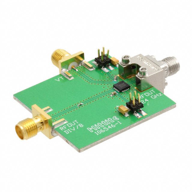
| 描述 | EVAL BOARD FOR ISL9440 |
| 产品分类 | |
| 品牌 | Intersil |
| 数据手册 | |
| 产品图片 |
|
| 产品型号 | ISL9440EVAL2Z |
| rohs | 无铅 / 符合限制有害物质指令(RoHS)规范要求 |
| 产品系列 | - |
| 主要用途 | DC/DC,LDO 步降 |
| 产品培训模块 | http://www.digikey.cn/PTM/IndividualPTM.page?site=cn&lang=zhs&ptm=25593 |
| 使用的IC/零件 | ISL9440 |
| 功率-输出 | - |
| 所含物品 | 板 |
| 板类型 | 完全填充 |
| 标准包装 | 1 |
| 电压-输入 | 6 V ~ 16 V |
| 电压-输出 | 1.5V,2.5V,5V,3.3V |
| 电流-输出 | 6A,6A,4A,800mA |
| 稳压器拓扑 | 降压 |
| 输出和类型 | 4,非隔离 |
| 频率-开关 | 300kHz |


- 商务部:美国ITC正式对集成电路等产品启动337调查
- 曝三星4nm工艺存在良率问题 高通将骁龙8 Gen1或转产台积电
- 太阳诱电将投资9.5亿元在常州建新厂生产MLCC 预计2023年完工
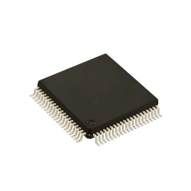
- 英特尔发布欧洲新工厂建设计划 深化IDM 2.0 战略
- 台积电先进制程称霸业界 有大客户加持明年业绩稳了
- 达到5530亿美元!SIA预计今年全球半导体销售额将创下新高
- 英特尔拟将自动驾驶子公司Mobileye上市 估值或超500亿美元
- 三星加码芯片和SET,合并消费电子和移动部门,撤换高东真等 CEO
- 三星电子宣布重大人事变动 还合并消费电子和移动部门
- 海关总署:前11个月进口集成电路产品价值2.52万亿元 增长14.8%


PDF Datasheet 数据手册内容提取
USER’S MANUAL ISL9440EVAL2Z AN1550 Triple PWM Step-Down Synchronous Buck Controller and One LDO Rev 0.00 Evaluation Board Mar 8, 2010 ISL9440EVAL2Z Evaluation TABLE 1. FEATURES OF ISL944xx FAMILY Board SWITCHING SOFT-STARTING PART EARLY FREQUENCY TIME The ISL9440EVAL2Z evaluation board features the NUMBER WARNING (kHz) (ms) ISL9440. The ISL9440 is a quad-output controller that integrates three PWM synchronous buck controllers and ISL9440 Yes 300 1.7 one low-dropout linear regulator controller. The ISL9440 ISL9440A Yes 600 1.7 offers internal soft-start, independent enable functions and integrates UV/OV/OC/OT protection. Its current ISL9441 No 300 1.7 mode control architecture and internal compensation ISL9440B Yes 300 Programmable network keep peripheral component count minimal. Switching frequency of 300kHz minimizes losses while ISL9440C Yes 600 Programmable the strong gate drivers deliver up to 12A to each PWM The ISL9440EVAL2Z is easy to set up to evaluate the channel. performance of the ISL9440. Please refer to the Table 1 shows the difference in terms of ISL944xx family “Electrical Specifications” table on page2 for typical features. performance summary. FIGURE 1. ISL9440EVAL2Z EVALUATION BOARD AN1550 Rev 0.00 Page 1 of 12 Mar 8, 2010
ISL9440EVAL2Z Electrical Specifications Recommended operation conditions unless otherwise noted. Refer to the “Schematic” on page7 and “Typical Evaluation Board Performance Curves” on page4. PARAMETER TEST CONDITIONS MIN TYP MAX UNITS V All outputs are in regulation 6.0 12 16 V IN V 1 1.45 1.50 1.54 V OUT V 2 2.43 2.50 2.57 V OUT V 3 4.85 5.0 5.15 V OUT V 4 3.20 3.30 2.39 V OUT PWM1 Rated Current V = 12V, T = +25°C, No forced airflow, All 6 7 A IN A three PWM outputs are fully loaded PWM2 Rated Current 6 7 A PWM3 Rated Current 4 5 A LDO Rated Current R = 0, R is not populated 0.8 1.0 A 4 7 V 1 Peak-to-Peak Ripple V = 12V, All three PWM outputs are fully loaded, 29.4 mV OUT IN P-P Oscilloscope is with full bandwidth V 2 Peak-to-Peak Ripple 15.7 mV OUT P-P V 3 Peak-to-Peak Ripple 31.4 mV OUT P-P What’s Inside Quick Test Guide The evaluation board kit contains the following materials: 1. Ensure that the circuit is correctly connected to the supply and electronic loads prior to applying any • The ISL9440EVAL2Z power. Please refer to Figure 2 for proper set-up. • The ISL9440, ISL9440A, ISL9441 Datasheet FN6383 2. Connect Jumpers J , J and J in the ENx positions. 3 4 5 • This Evaluation Board Kit document (AN1550) 3. Turn on the power supply. 4. Adjust input voltage V within the specified range Recommended Equipment IN and observe output voltage. The output voltage The following materials are recommended to perform variation should be within 3%. testing: 5. Adjust load current within the specified range and observe output voltage. The output voltage • 0V to 20V Power Supply with at least 10A source variation should be within 3%. current capability 6. Use oscilloscope to observe output voltage ripple • Three electronic loads capable of sinking current up and phase node ringing. For accurate measurement, to7A please follow setup shown in Figure 3. • Digital Multimeters (DMMs) • 100MHz Quad-Trace Oscilloscope • Signal Generator (for load transient tests) AN1550 Rev 0.00 Page 2 of 12 Mar 8, 2010
ISL9440EVAL2Z FIGURE 2. PROPER TEST SET-UP Load Transient Circuit Set-up 1. Select a SOIC8 N-Channel MOSFET with VDS breakdown >20V. 2. Install the load transient circuit as indicated on the schematic. Refer to Figure 4 for detail. OOOUUUTTPTPUPUTUT TC C ACAPA P P 3. R , R and R are 10k resistors for discharging OOORRR MMMOOOSSSFEFFTEE TT 27 22 25 the MOSFET gates. 4. R , R and R are current sensing resistors to 26 23 24 monitor the load step. For accurate measurement, FIGURE 3. PROPER PROBE SET-UP TO MEASURE please use 5% tolerance sensing resistor or better. OUTPUT RIPPLE AND PHASE NODE To alleviate thermal stress, use 0.1or smaller RINGING resistance. The resistance of the sensing resistors sets the current scale on the oscilloscope. 5. Apply pulse square waveform across R , R or 27 22 R . The duty cycle of the pulse waveform should be 25 small (<5%) to limit thermal stress on current sensing resistor and the MOSFETs (M , M or M ). 8 6 7 6. The amplitude of the clock sets the current step amplitude. Adjust the clock amplitude and slew rate to set the current step and slew rate. 7. Monitor overshoot and undershoot at corresponding output. AN1550 Rev 0.00 Page 3 of 12 Mar 8, 2010
ISL9440EVAL2Z . OPT. LOAD TRAN. OPT R27 M8 OPT R26 OPT FIGURE 4. LOAD TRANSIENT CIRCUIT FOR PWM1 Typical Evaluation Board Performance Curves V = 12V, IN Unless Otherwise Noted. 95 100 VIN = 9V VIN = 9V 90 95 85 (%) 7850 VIN = 12V VIN = 16V Y (%) 8950 VIN = 12V VIN = 16V Y C 80 C 70 N EN 65 CIE 75 FFICI 60 EFFI 6750 E 55 50 60 45 55 40 50 0 1 2 3 4 5 6 7 8 0 1 2 3 4 5 6 7 LOAD CURRENT (A) LOAD CURRENT (A) FIGURE 5. PWM1 EFFICIENCY vs LOAD (V = 1.5V) FIGURE 6. PWM2 EFFICIENCY vs LOAD (V = 2.5V) O O 100 VIN = 9V 1.510 95 90 %) 85 VIN = 12V VIN = 16V 1.505 NCY ( 7850 (V)T1 1.500 E U CI 70 VO I F F 65 E 1.495 60 55 50 1.490 0 1 2 3 4 5 5 7 9 11 13 15 17 19 LOAD CURRENT (A) INPUT VOLTAGE (V) FIGURE 7. PWM3 EFFICIENCY vs LOAD (V = 5.0V) FIGURE 8. PWM1 LINE REGULATION (I = I = 6A, O O1 O2 I = 4A) O3 AN1550 Rev 0.00 Page 4 of 12 Mar 8, 2010
ISL9440EVAL2Z Typical Evaluation Board Performance Curves V = 12V, IN Unless Otherwise Noted. (Continued) 2.510 5.025 2.505 5.000 V) V) V (OUT2 2.500 V (OUT2 4.975 2.495 4.950 2.490 4.925 5 7 9 11 13 15 17 19 5 7 9 11 13 15 17 19 INPUT VOLTAGE (V) INPUT VOLTAGE (V) FIGURE 9. PWM2 LINE REGULATION (I = I = 6A, FIGURE 10. PWM3 LINE REGULATION (I = I = 6A, O1 O2 O1 O2 I = 4A) I = 4A) O3 O3 1.510 2.510 1.505 2.505 V) V) (OUT1 1.500 (OUT2 2.500 V V 1.495 2.495 1.490 2.490 0 1 2 3 4 5 6 7 8 0 1 2 3 4 5 6 7 8 LOAD CURRENT (A) LOAD CURRENT (A) FIGURE 11. PWM1 LOAD REGULATION (V = 12V, FIGURE 12. PWM2 LOAD REGULATION (V = 12V, IN IN I = 6A, I = 4A) I = 6A, I = 4A) O2 O3 O1 O3 5.025 VOUT1(AC), 10mV/DIV 5.000 ) V ( 2 4.975 T U O V 4.950 4.925 1µs/DIV 0 1 2 3 4 5 LOAD CURRENT (A) FIGURE 13. PWM3 LOAD REGULATION (V = 12V, FIGURE 14. PWM1 OUTPUT RIPPLE UNDER MAX LOAD IN I = 6A, I = 3A) (V = 12V, I = I = 6A, I = 4A, FULL O1 O2 IN O1 O2 O3 BANDWIDTH) AT V = 1.5V O AN1550 Rev 0.00 Page 5 of 12 Mar 8, 2010
ISL9440EVAL2Z Typical Evaluation Board Performance Curves V = 12V, IN Unless Otherwise Noted. (Continued) VOUT2(AC), 10mV/DIV VOUT3(AC), 20mV/DIV 1µs/DIV 1µs/DIV FIGURE 15. PWM2 OUTPUT RIPPLE UNDER MAX LOAD FIGURE 16. PWM3 OUTPUT RIPPLE UNDER MAX LOAD (V = 12V, I = I = 6A, I = 4A, FULL (V = 12V, I = I = 6A, I = 4A, FULL IN O1 O2 O3 IN O1 O2 O3 BANDWIDTH) AT V = 2.5V BANDWIDTH) AT V = 5V O O VOUT1(AC), 50mV/DIV VOUT2(AC, 50mV/DIV) ISTEP, 2A/DIV ISTEP, 2A/DIV 50µs/DIV 50µs/DIV FIGURE 17. PWM1 LOAD TRANSIENT RESPONSE FIGURE 18. PWM2 LOAD TRANSIENT RESPONSE (LOAD STEP FROM 1.5A TO 4.5A) AT (LOAD STEP FROM 1.5A TO 4.5A) AT V =1.5V V =2.5V O O VOUT1, 1V/DIV VOUT2, 1V/DIV VOUT3(AC), 20mV/DIV VOUT3, 2V/DIV VOUT4, 1V/DIV ISTEP, 1A/DIV 500µs/DIV 50µs/DIV FIGURE 19. PWM3 LOAD TRANSIENT RESPONSE FIGURE 20. SOFT-START WAVEFORMS (LOADSTEP FROM 1A TO 3A) AT V = 5V O AN1550 Rev 0.00 Page 6 of 12 Mar 8, 2010
MA Schematic IS aN L r 815 94 , 250 40 0 E 1R V 0e A v 0 L2 .0 Z 0 P a g e 7 o f 1 2
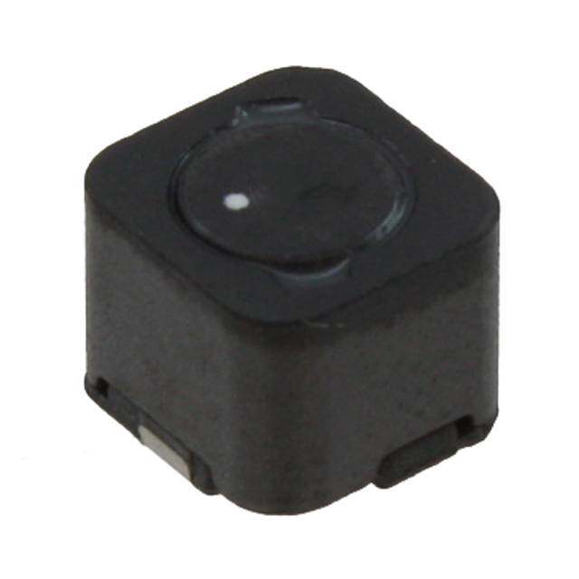
ISL9440EVAL2Z TABLE 2. BILL OF MATERIALS ESSENTIAL COMPONENTS ITEM QTY PART REFERENCE VALUE DESCRIPTION PART # MANUFACTURER 1 3 CB1, CB2, CB3 0.1µF CAP Ceramic X7R, 16V, SMD, 0603 Generic 2 1 CFIN1 0.47µF CAP Ceramic Y5V, 50V, SMD, 0603 Generic 3 2 CIN1, CIN2 100µF Alum. Elec. CAP 35V EEU-FC1V101 Panasonic 4 4 CIN3, CIN4, CIN5, CIN6 10µF CAP Ceramic X5R, 35V, SMD, 1210 Generic 5 3 CL1, CL2, CL3 820pF CAP Ceramic X5R, 50V, SMD, 0603 Generic 6 2 CO11, CO12 330µF POSCAP, 2.5V, SMD, D2E 2R5TPE330M7 Sanyo 7 5 CO13, CO14, CO24, 10µF CAP Ceramic X5R, 6.3V, SMD, 0805 Generic CO33,CO41 8 2 CO21, CO22 330µF POSCAP, 6.3V, SMD, D3L 6TPF330M9L Sanyo 9 1 CO31 220uF POSCAP, 6.3V, SMD 6TPE220MI Sanyo 10 1 CO42 100µF POSCAP, 4.0V, SMD, B 4TPE100MZB Sanyo 11 1 CVCC1 4.7µF CAP Ceramic X5R, 6.3V, SMD, 0805 Generic 12 1 Cff1 220pF CAP Ceramic X7R, 50V, SMD, 0603 Generic 13 1 Cff2 1200pF CAP Ceramic X7R, 50V, SMD, 0603 Generic 14 1 Cff3 270pF CAP Ceramic X7R, 50V, SMD, 0603 15 1 C1 0.22µF CAP Ceramic X5R, 16V, SMD, 0603 Generic 16 1 C2 22pF CAP Ceramic X5R, 16V, SMD, 0603 Generic 17 1 C3 1µF CAP Ceramic X5R, 16V, SMD, 0603 Generic 18 1 L1 2.0µH SHIELDED INDUCTOR #744325550 Wurth 19 1 L2 2.8µH SHIELDED INDUCTOR #7443552280 Wurth 20 1 L3 5.5µH SHIELDED INDUCTOR #744325550 Wurth 21 3 M1, M2, M3 Dual N MOSFET, 30V, SOIC8 IRF7907 International Rectifier 22 1 M4 P MOSFET, SOIC8 Si4423DY Vishay 23 1 R 10 RESISTOR, SMD, 0805, 10% Generic FIN1 24 3 RL1, RL2, RL3 1.2 RESISTOR, SMD, 0603, 10% Generic 25 1 RPG1 100k RESISTOR, SMD, 0603, 1% Generic 26 1 ROC1, ROC3 120k RESISTOR, SMD, 0603, 1% Generic 27 1 ROC2 160k RESISTOR, SMD, 0603, 1% Generic 28 2 R , R 1.5k RESISTOR, SMD, 0603, 1% Generic SEN1 SEN3 29 1 R 2k RESISTOR, SMD, 0603, 1% Generic SEN2 30 1 R1 9.31k RESISTOR, SMD, 0603, 1% Generic 31 1 R2 10.7k RESISTOR, SMD, 0603, 1% Generic 32 1 R3 105k RESISTOR, SMD, 0603, 1% Generic 33 1 R5 51 RESISTOR, SMD, 0603, 1% Generic 34 1 R6 20k RESISTOR, SMD, 0603, 1% Generic 35 1 R8 24.3k RESISTOR, SMD, 0603, 1% Generic 36 1 R9 15k RESISTOR, SMD, 0603, 1% Generic 37 1 R10 4.75k RESISTOR, SMD, 0603, 1% Generic AN1550 Rev 0.00 Page 8 of 12 Mar 8, 2010
ISL9440EVAL2Z TABLE 2. BILL OF MATERIALS (Continued) ESSENTIAL COMPONENTS ITEM QTY PART REFERENCE VALUE DESCRIPTION PART # MANUFACTURER 38 1 R11 11.5k RESISTOR, SMD, 0603, 1% Generic 39 1 U1 QUAD OUTPUT CONTROLLER ISL9440IRZ Intersil OPTIONAL COMPONENTS OR RESISTOR JUMPERS ITEM QTY REFERENCE VALUE DESCRIPTION PART # MANUFACTURER 40 10 R4, R12, R13, R14, 0 RESISTOR Jumpers, SMD, 0603, 10% Generic R15, R16, R17, R18, R19, R20, R21 41 2 CO23, CO32 CO34 DNP 42 3 Cp1, Cp2, Cp3 DNP 42 1 M5 DNP P MOSFET TO-252 43 3 M6, M7, M8 DNP N MOSFET 44 4 R7, R22, R25, R27 DNP RESISTOR, SMD, 0603 45 3 R23, R24, R26 DNP RESISTOR, SMD, 1206 EVALUATION BOARD HARDWARE ITEM QTY REFERENCE VALUE DESCRIPTION PART # MANUFACTURER 46 3 J3, J4, J5 3 Head Jumper 68000-236HLF Generic 47 11 TP1, TP2, TP3, TP4, TEST POINT 5007 Keystone TP6, TP17, TP11, TP12, TP13, TP14, TP7 48 9 TP8, TP10, TP16, TP19, GND TURRET 1514-2 Keystone TP21, TP9, TP5, TP15, TP20 AN1550 Rev 0.00 Page 9 of 12 Mar 8, 2010
MA ISL9440EVAL2Z PCB Layout IS aN L r 815 94 , 250 40 0 E 1R V 0e A v 0 L2 .0 Z 0 FIGURE 21. TOP LAYER FIGURE 22. SECOND LAYER (SOLID GROUND) P a g e 1 0 o f 1 2
MaAN ISL9440EVAL2Z PCB Layout (Continued) ISL r 815 94 , 250 40 0 E 1R V 0e A v 0 L2 .0 Z 0 FIGURE 23. THIRD LAYER FIGURE 24. BOTTOM LAYER P a g e 1 1 o f 1 2
Notice 1. Descriptions of circuits, software and other related information in this document are provided only to illustrate the operation of semiconductor products and application examples. You are fully responsible for the incorporation or any other use of the circuits, software, and information in the design of your product or system. Renesas Electronics disclaims any and all liability for any losses and damages incurred by you or third parties arising from the use of these circuits, software, or information. 2. Renesas Electronics hereby expressly disclaims any warranties against and liability for infringement or any other claims involving patents, copyrights, or other intellectual property rights of third parties, by or arising from the use of Renesas Electronics products or technical information described in this document, including but not limited to, the product data, drawings, charts, programs, algorithms, and application examples. 3. No license, express, implied or otherwise, is granted hereby under any patents, copyrights or other intellectual property rights of Renesas Electronics or others. 4. You shall not alter, modify, copy, or reverse engineer any Renesas Electronics product, whether in whole or in part. Renesas Electronics disclaims any and all liability for any losses or damages incurred by you or third parties arising from such alteration, modification, copying or reverse engineering. 5. Renesas Electronics products are classified according to the following two quality grades: “Standard” and “High Quality”. The intended applications for each Renesas Electronics product depends on the product’s quality grade, as indicated below. "Standard": Computers; office equipment; communications equipment; test and measurement equipment; audio and visual equipment; home electronic appliances; machine tools; personal electronic equipment; industrial robots; etc. "High Quality": Transportation equipment (automobiles, trains, ships, etc.); traffic control (traffic lights); large-scale communication equipment; key financial terminal systems; safety control equipment; etc. Unless expressly designated as a high reliability product or a product for harsh environments in a Renesas Electronics data sheet or other Renesas Electronics document, Renesas Electronics products are not intended or authorized for use in products or systems that may pose a direct threat to human life or bodily injury (artificial life support devices or systems; surgical implantations; etc.), or may cause serious property damage (space system; undersea repeaters; nuclear power control systems; aircraft control systems; key plant systems; military equipment; etc.). Renesas Electronics disclaims any and all liability for any damages or losses incurred by you or any third parties arising from the use of any Renesas Electronics product that is inconsistent with any Renesas Electronics data sheet, user’s manual or other Renesas Electronics document. 6. When using Renesas Electronics products, refer to the latest product information (data sheets, user’s manuals, application notes, “General Notes for Handling and Using Semiconductor Devices” in the reliability handbook, etc.), and ensure that usage conditions are within the ranges specified by Renesas Electronics with respect to maximum ratings, operating power supply voltage range, heat dissipation characteristics, installation, etc. Renesas Electronics disclaims any and all liability for any malfunctions, failure or accident arising out of the use of Renesas Electronics products outside of such specified ranges. 7. Although Renesas Electronics endeavors to improve the quality and reliability of Renesas Electronics products, semiconductor products have specific characteristics, such as the occurrence of failure at a certain rate and malfunctions under certain use conditions. Unless designated as a high reliability product or a product for harsh environments in a Renesas Electronics data sheet or other Renesas Electronics document, Renesas Electronics products are not subject to radiation resistance design. You are responsible for implementing safety measures to guard against the possibility of bodily injury, injury or damage caused by fire, and/or danger to the public in the event of a failure or malfunction of Renesas Electronics products, such as safety design for hardware and software, including but not limited to redundancy, fire control and malfunction prevention, appropriate treatment for aging degradation or any other appropriate measures. Because the evaluation of microcomputer software alone is very difficult and impractical, you are responsible for evaluating the safety of the final products or systems manufactured by you. 8. Please contact a Renesas Electronics sales office for details as to environmental matters such as the environmental compatibility of each Renesas Electronics product. You are responsible for carefully and sufficiently investigating applicable laws and regulations that regulate the inclusion or use of controlled substances, including without limitation, the EU RoHS Directive, and using Renesas Electronics products in compliance with all these applicable laws and regulations. Renesas Electronics disclaims any and all liability for damages or losses occurring as a result of your noncompliance with applicable laws and regulations. 9. Renesas Electronics products and technologies shall not be used for or incorporated into any products or systems whose manufacture, use, or sale is prohibited under any applicable domestic or foreign laws or regulations. You shall comply with any applicable export control laws and regulations promulgated and administered by the governments of any countries asserting jurisdiction over the parties or transactions. 10. It is the responsibility of the buyer or distributor of Renesas Electronics products, or any other party who distributes, disposes of, or otherwise sells or transfers the product to a third party, to notify such third party in advance of the contents and conditions set forth in this document. 11. This document shall not be reprinted, reproduced or duplicated in any form, in whole or in part, without prior written consent of Renesas Electronics. 12. Please contact a Renesas Electronics sales office if you have any questions regarding the information contained in this document or Renesas Electronics products. (Note 1) “Renesas Electronics” as used in this document means Renesas Electronics Corporation and also includes its directly or indirectly controlled subsidiaries. (Note 2) “Renesas Electronics product(s)” means any product developed or manufactured by or for Renesas Electronics. (Rev.4.0-1 November 2017) SALES OFFICES http://www.renesas.com Refer to "http://www.renesas.com/" for the latest and detailed information. Renesas Electronics America Inc. 1001 Murphy Ranch Road, Milpitas, CA 95035, U.S.A. Tel: +1-408-432-8888, Fax: +1-408-434-5351 Renesas Electronics Canada Limited 9251 Yonge Street, Suite 8309 Richmond Hill, Ontario Canada L4C 9T3 Tel: +1-905-237-2004 Renesas Electronics Europe Limited Dukes Meadow, Millboard Road, Bourne End, Buckinghamshire, SL8 5FH, U.K Tel: +44-1628-651-700, Fax: +44-1628-651-804 Renesas Electronics Europe GmbH Arcadiastrasse 10, 40472 Düsseldorf, Germany Tel: +49-211-6503-0, Fax: +49-211-6503-1327 Renesas Electronics (China) Co., Ltd. Room 1709 Quantum Plaza, No.27 ZhichunLu, Haidian District, Beijing, 100191 P. R. China Tel: +86-10-8235-1155, Fax: +86-10-8235-7679 Renesas Electronics (Shanghai) Co., Ltd. Unit 301, Tower A, Central Towers, 555 Langao Road, Putuo District, Shanghai, 200333 P. R. China Tel: +86-21-2226-0888, Fax: +86-21-2226-0999 Renesas Electronics Hong Kong Limited Unit 1601-1611, 16/F., Tower 2, Grand Century Place, 193 Prince Edward Road West, Mongkok, Kowloon, Hong Kong Tel: +852-2265-6688, Fax: +852 2886-9022 Renesas Electronics Taiwan Co., Ltd. 13F, No. 363, Fu Shing North Road, Taipei 10543, Taiwan Tel: +886-2-8175-9600, Fax: +886 2-8175-9670 Renesas Electronics Singapore Pte. Ltd. 80 Bendemeer Road, Unit #06-02 Hyflux Innovation Centre, Singapore 339949 Tel: +65-6213-0200, Fax: +65-6213-0300 Renesas Electronics Malaysia Sdn.Bhd. Unit 1207, Block B, Menara Amcorp, Amcorp Trade Centre, No. 18, Jln Persiaran Barat, 46050 Petaling Jaya, Selangor Darul Ehsan, Malaysia Tel: +60-3-7955-9390, Fax: +60-3-7955-9510 Renesas Electronics India Pvt. Ltd. No.777C, 100 Feet Road, HAL 2nd Stage, Indiranagar, Bangalore 560 038, India Tel: +91-80-67208700, Fax: +91-80-67208777 Renesas Electronics Korea Co., Ltd. 17F, KAMCO Yangjae Tower, 262, Gangnam-daero, Gangnam-gu, Seoul, 06265 Korea Tel: +82-2-558-3737, Fax: +82-2-558-5338 © 2018 Renesas Electronics Corporation. All rights reserved. Colophon 7.0
Mouser Electronics Authorized Distributor Click to View Pricing, Inventory, Delivery & Lifecycle Information: R enesas Electronics: ISL9440EVAL2Z