ICGOO在线商城 > ISL6446IAZ-T7A
- 型号: ISL6446IAZ-T7A
- 制造商: Intersil
- 库位|库存: xxxx|xxxx
- 要求:
| 数量阶梯 | 香港交货 | 国内含税 |
| +xxxx | $xxxx | ¥xxxx |
查看当月历史价格
查看今年历史价格
ISL6446IAZ-T7A产品简介:
ICGOO电子元器件商城为您提供ISL6446IAZ-T7A由Intersil设计生产,在icgoo商城现货销售,并且可以通过原厂、代理商等渠道进行代购。 提供ISL6446IAZ-T7A价格参考以及IntersilISL6446IAZ-T7A封装/规格参数等产品信息。 你可以下载ISL6446IAZ-T7A参考资料、Datasheet数据手册功能说明书, 资料中有ISL6446IAZ-T7A详细功能的应用电路图电压和使用方法及教程。
| 参数 | 数值 |
| 产品目录 | 集成电路 (IC) |
| 描述 | IC REG TRPL BUCK/LINEAR 24QSOP |
| 产品分类 | |
| 品牌 | Intersil |
| 数据手册 | |
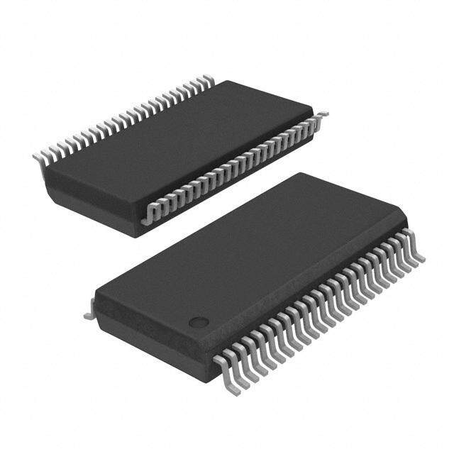
| 产品图片 |
|
| 产品型号 | ISL6446IAZ-T7A |
| rohs | 无铅 / 符合限制有害物质指令(RoHS)规范要求 |
| 产品系列 | - |
| 供应商器件封装 | 24-QSOP |
| 其它名称 | ISL6446IAZ-T7ATR |
| 功能 | 任何功能 |
| 包装 | 带卷 (TR) |
| 安装类型 | 表面贴装 |
| 封装/外壳 | 24-SSOP(0.154",3.90mm 宽) |
| 工作温度 | -40°C ~ 85°C |
| 带LED驱动器 | 无 |
| 带定序器 | 无 |
| 带监控器 | 无 |
| 拓扑 | 降压(降压)同步(2),线性(LDO)(1) |
| 标准包装 | 250 |
| 电压-电源 | 4.5 V ~ 5.5 V |
| 电压/电流-输出1 | 控制器 |
| 电压/电流-输出2 | 控制器 |
| 电压/电流-输出3 | 控制器 |
| 输出数 | 3 |
| 频率-开关 | 100kHz ~ 2.6MHz |


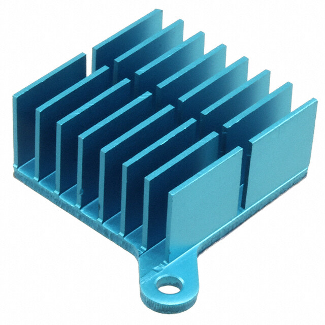


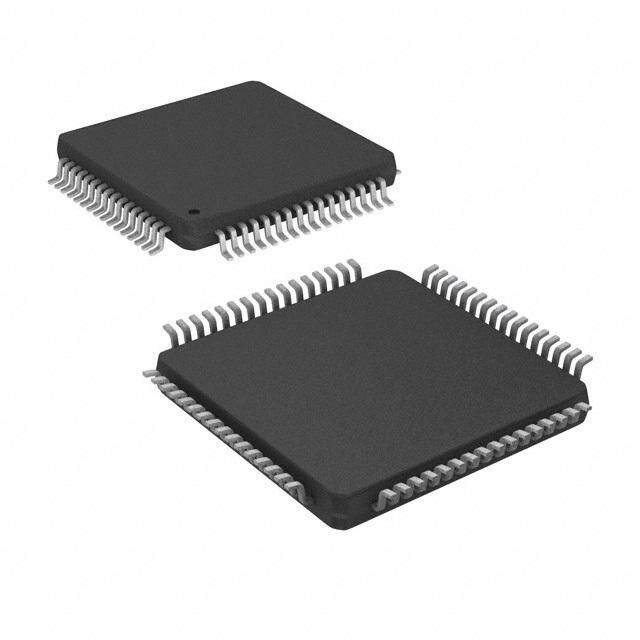
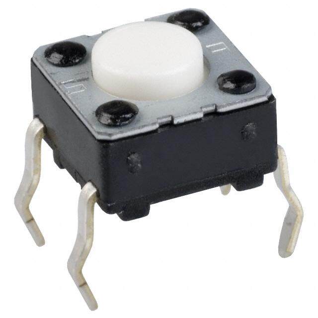

- 商务部:美国ITC正式对集成电路等产品启动337调查
- 曝三星4nm工艺存在良率问题 高通将骁龙8 Gen1或转产台积电
- 太阳诱电将投资9.5亿元在常州建新厂生产MLCC 预计2023年完工
- 英特尔发布欧洲新工厂建设计划 深化IDM 2.0 战略
- 台积电先进制程称霸业界 有大客户加持明年业绩稳了
- 达到5530亿美元!SIA预计今年全球半导体销售额将创下新高
- 英特尔拟将自动驾驶子公司Mobileye上市 估值或超500亿美元
- 三星加码芯片和SET,合并消费电子和移动部门,撤换高东真等 CEO
- 三星电子宣布重大人事变动 还合并消费电子和移动部门
- 海关总署:前11个月进口集成电路产品价值2.52万亿元 增长14.8%


PDF Datasheet 数据手册内容提取
DATASHEET ISL6446 FN7944 Dual (180°Out-of-Phase) PWM and Linear Controller Rev 2.00 October 12, 2015 The ISL6446 is a high-performance, triple output controller Features that provides a single high-frequency power solution primarily for broadband, DSL and networking applications. This device • 4.5V to 5.5V or 5.5V to 24V input voltage range integrates complete control, monitoring and protection • Three programmable power output voltages functions for two synchronous buck PWM controllers and one - Two PWM controllers with out-of-phase operation linear controller. Input voltage ripple and total RMS input - Voltage-mode PWM control current is substantially reduced by synchronized 180° out-of-phase operation of the two PWMs. - One linear controller The two PWM buck converters provide simple voltage mode • Programmable switching frequency from 100kHz to 2.5MHz control. The output voltage of the converters can be precisely • Fast transient response regulated to as low as 0.6V, with a maximum tolerance of - High-bandwidth error amplifier ±1.5% over-temperature and line variations. Programmable switching frequency down to 100kHz provides optimized low • Extensive circuit protection functions cost solution for ATX power supplies. It’s also able to operate - Undervoltage and over-temperature up to 2.5MHz to deliver compact solutions. The linear - Overvoltage with latch-off mode controller provides a low-current output. - Programmable overcurrent limit with latch-off mode Each PWM controller has soft-start and independent enable - Lossless current sensing (no sense resistor needed) functions combined on a single pin. A capacitor from SS/EN to ground sets the soft-start time; pulling SS/EN pin below 1V • Externally adjustable soft-start time disables the controller. Both outputs can soft-start into a - Independent enable control prebiased load. - Voltage tracking capability The ISL6446 incorporates robust protection features. An - Able to soft-start into a prebiased load adjustable overcurrent protection circuit monitors the output current by sensing the voltage drop across the upper MOSFET • PGOOD output with delay rDS(ON). Latch-off mode overcurrent operation protects the Applications DC/DC converters from damage under overload and short-circuit conditions. A PGOOD signal is issued when • ATX power supplies soft-start is complete and PWM outputs are within 10% of • DSP, ASIC and FPGA point of load regulation their regulated values and the linear regulator output is higher than 75% of its nominal value. Thermal shutdown circuitry • Industrial and security networking applications turns the device off if the IC temperature exceeds +150°C. VCC VIN CVCC ROCSET1 100 VOUT1 CoF mNeepe adtewnbndoasrcakktion CFBO1MVPC1C OBVCOISNOETT11CBOOTQ11CVIONCC1ISN =E1 TV1IN 9968 UGATE1 VOUT2 CoF mNeepe adtewnbndoasrcakktion R1 FCBO2MP2ISL644P6LHGAASTEE11ROCSQE2T2VIN2L 1= VINCOVUOT1UT1 NCY (%) 999024 VOUT = 3.3V VOUT = 5V R2 OUBGCOSAOETETT222 CBOOQT23 COCCISNE2T2 EFFICIE 88 86 PHASE2 L2 VOUT2 LGATE2 COUT2 84 PGOOD Q4 RT SS1/EN1 82 SS2/EN2 LCDR 80 LCFB 0 5 10 15 20 25 SGND PGND LOAD CURRENT (A) FIGURE 1. TYPICAL APPLICATION FIGURE 2. EFFICIENCY vs LOAD CURRENT (OBTAINED FROM ISL6446EVAL1Z) FN7944 Rev 2.00 Page 1 of 19 October 12, 2015
ISL6446 Pin Configuration ISL6446 (24 LD QSOP) TOP VIEW OCSET1 1 24 VIN SS1/EN1 2 23 BOOT1 COMP1 3 22 UGATE1 FB1 4 21 PHASE1 RT 5 20 LGATE1 SGND 6 19 VCC LCDR 7 18 PGND LCFB 8 17 LGATE2 FB2 9 16 PHASE2 COMP2 10 15 UGATE2 SS2/EN2 11 14 BOOT2 OCSET2 12 13 PGOOD Pin Descriptions SYMBOL PIN # DESCRIPTION BOOT2, 1 14, 23 These pins power are the upper MOSFET drivers of each PWM converter. The anode of each internal bootstrap diode is connected to the VCC pin. The cathode of the bootstrap diode is connected to this pin, which should also connect to the bootstrap capacitor. UGATE2, 1 15, 22 These pins provide the gate drive for upper MOSFETs, bootstrapped from the VCC pin. PHASE2, 1 16, 21 These are the junction points of the upper MOSFET sources, the output filter inductor and lower MOSFET drains. Connect these pins accordingly to the respective converter. LGATE2, 1 17, 20 These are the outputs of the lower N-Channel MOSFET drivers, sourced from the VCC pin. PGND 18 This pin provides the power ground connection for the lower gate drivers. This pin should be connected to the source of the lower MOSFET for PWM1 and PWM2 and the negative terminals of the external input capacitors. FB1, 2 4, 9 These pins are connected to the feedback resistor divider and provide the voltage feedback signals for the respective controller. They set the output voltage of the converter. In addition, the PGOOD circuit and OVP circuit use these inputs to monitor the output voltage status. COMP1, 2 3, 10 These pins are the error amplifier outputs for the respective PWM. They are used, along with the FB pins, as the compensation point for the PWM error amplifier. PGOOD 13 This is an open drain logic output used to indicate the status of the output voltages. This pin is pulled low when either of the two PWM outputs is not within 10% of the respective nominal voltage or when the linear output drops below 75% of its nominal voltage. To maintain the PGOOD function if the linear output is not used, connect LCFB to VCC. SGND 6 This is the signal ground, common to both controllers, and must be routed separately from the high current grounds (PGND). All voltage levels are measured with respect to this pin. VIN 24 This pin powers the controllers with an internal linear regulator (if VIN > 5.5V) and must be closely decoupled to ground using a ceramic capacitor as close to the VIN pin as possible. The VIN is the input voltage applied to the upper FET of both converters. TABLE 1. INPUT SUPPLY CONFIGURATION INPUT PIN CONFIGURATION 5.5V to 24V Connect the input supply to the VIN pin. The VCC pin will provide a 5V output from the internal voltage regulator. 5V ±10% Connect the input supply to the VCC pin. VCC 19 This pin supplies the bias for the regulators, powers the low-side gate drivers and external boot circuitry for high-side gate drivers. The IC may be powered directly from a single 5V (±10%) supply at this pin; when used as a 5V supply input, this pin must be externally connected to VIN. When VIN > 5.5, VCC is the output of the internal 5V linear regulator output. The VCC pin must always be decoupled to power ground with a minimum of 1µF ceramic capacitor, placed very close to the pin. FN7944 Rev 2.00 Page 2 of 19 October 12, 2015
ISL6446 Pin Descriptions (Continued) SYMBOL PIN # DESCRIPTION RT 5 This is the operating frequency adjustment pin. By placing a resistor from this pin to the SGND, the oscillator frequency can be programmed from 100kHz to 2.5MHz. SS1/EN1 2, 11 These pins provide enable/disable and soft-start function for their respective controllers. The output is held off when the pin is SS2/EN2 pulled to ground. When the chip is enabled, the regulated 30µA pull-up current source charges the capacitor connected from the pin to ground. The output voltage of the converter follows the ramping voltage on the SS/EN pin. See “Soft-Start and Voltage Tracking” on page11 for more details. LCFB 8 This pin is the feedback pin for the linear controller. An external voltage divider network connected to this pin sets the output voltage of the linear controller. If the linear controller is not used, tie this pin to VCC. LCDR 7 Open drain output PNP Transistor or P-channel MOSFET Driver. The LCDR connects to the base of an external PNP pass transistor or the gate of the MOSFET to form a positive linear regulator. A small resistor can be inserted between the LCDR and the base of the PNP pass transistor or the gate of the MOSFET to alleviate thermal stress at output short condition. OCSET1, 2 1, 12 These pins are the overcurrent set points for the respective PWM controllers. Connect a resistor (ROCSET) from this pin to the drain of the upper MOSFET. ROCSET, an internal 110µA current source, and the upper MOSFET ON-resistance rDS(ON) set the converter overcurrent (OC) trip point according to Equation1: I R I = --O-----C----S----E----T-------------O-----C----S----E----T-- (EQ. 1) OC r DSON IOC includes the DC load current, as well as the ripple current. An overcurrent trip initiates hiccup mode. The voltage on the OCSET pin should not exceed 0.7V above the VIN pin voltage for proper current sensing when the UGATE is turned on. Ordering Information PART NUMBER PART TEMP PACKAGE PKG. (Notes1, 2, 3) MARKING RANGE (°C) (RoHS Compliant) DWG. # ISL6446IAZ ISL 6446IAZ -40 to +85 24 Ld QSOP M24.15 NOTES: 1. Add “-T*” suffix for tape and reel. Please refer to TB347 for details on reel specifications. 2. These Intersil Pb-free plastic packaged products employ special Pb-free material sets, molding compounds/die attach materials, and 100% matte tin plate plus anneal (e3 termination finish, which is RoHS compliant and compatible with both SnPb and Pb-free soldering operations). Intersil Pb-free products are MSL classified at Pb-free peak reflow temperatures that meet or exceed the Pb-free requirements of IPC/JEDEC J STD-020. 3. For Moisture Sensitivity Level (MSL), please see device information page for ISL6446. For more information on MSL please see tech brief TB363. FN7944 Rev 2.00 Page 3 of 19 October 12, 2015
ISL6446 Block Diagram VCC VIN VCC REFERENCE POWE R-ON 5V LINEAR 30BµAIAS1 0C0UµRAR 0E.6NVT ANDR CEOSNETTR OL REGUL ATOR 110µA OCSET1 VCC BOOT1 UVP1 OVP1 PG1 EN1 UGATE1 COMP1 OUTPUT1 DRIVERS GATE CONTROL PHASE1 FB1 - PWM1 LOGIC VCC + DEAD TIME 0.6V + CONTROL FAULT1 - LGATE1 UVP1 OVERCURRENT OVP1 VCC5 VCC5 PG1 PGND EN1 30µA 30µA SS1 RAMP1 0° STARTUP 110µA CLOCK AND OCSET2 SS1/EN1 SS1 EN1 SAWTOOTH GENERATOR VCC BOOT2 SS2/EN2 SS2 EN2 UVP2 OVP2 PG2 FAULT2 RAMP2 EN2 UGATE2 UVP2 180° OUTPUT2 OVP2 DRIVERS PG2 PHASE2 EN2 GATE CONTROL SS2 - PWM2 LOGIC VCC 0.6V + DEAD TIME + CONTROL LGATE2 FB2 - OVERCURRENT COMP2 PGND FAULT3 PG3 LCFB RT PG1 PG2 - 0.6V PGOOD PG3 gm*VE + LCFB LCDR SGND PGND FIGURE 3. BLOCK DIAGRAM FN7944 Rev 2.00 Page 4 of 19 October 12, 2015
ISL6446 Typical Application Schematic VOLTAGE INPUTS REQUIRED VIN (4.5V TO 24V) = VIN1 = VIN2 VCC VIN VCC (5V; INTERNAL IF VIN > 5.6V) OPTIONAL VIN3 (VCC) FOR LINEAR CONNECTION (FOR VIN = VCC = 5V) CVCC CVIN TYPE-3 COMPENSATION SHOWN C102 ROCSET1 VIN1 = VIN VCC VIN COMP1 R102 C101 OCSET1 COCSET1 VOUT1 R101 BOOT1 CBOOT1 FB1 Q101 CIN1 UGATE1 R103 C103 R100 0.9µH VOUT1 C202 PHASE1 L100 LGATE1 COMP2 COUT1 R202 C201 Q102 2x680µF/18m 2x100µF VOUT2 R201 1x47µF FB2 ROCSET2 VIN2 = VIN R203 C203 R200 ISL6446 OCSET2 COCSET2 TYPE-3 COMPENSATION SHOWN BOOT2 CBOOT2 Q201 CIN2 UGATE2 0.9µH VCC VOUT2 PHASE2 L200 COUT2 RPGOOD LGATE2 Q202 2x680µF/18m 2x100µF PGOOD R304 VIN3 RT C301 SS1/EN1 R303 R302 CIN3 LCDR SS2/EN2 Q301 LCFB VOUT3 CSS1/EN1 CSS2/EN2 RRT R301 SGND PGND R300 COUT3 FIGURE 4. ISL6446 TYPICAL APPLICATION FN7944 Rev 2.00 Page 5 of 19 October 12, 2015
ISL6446 Absolute Maximum Ratings Thermal Information (Note4) SS1/EN1, SS2/EN2, COMP1, COMP2 to SGND . . . . . . . . . . -0.3V to +6.0V Thermal Resistance (Typical) JA (°C/W) JC (°C/W) VCC, FB1, FB2, RT, PGOOD to SGND . . . . . . . . . . . . . . . . . . . -0.3V to +6.0V QSOP Package (Notes5, 6). . . . . . . . . . . . . 75 36 LCDR, LCFB to SGND . . . . . . . . . . . . . . . . . . . . . . . . . . . . . . . . -0.3V to +6.0V Maximum Junction Temperature (Plastic Package) . . . .-55°C to +150°C VIN, OCSET1 and OCSET2 to PGND . . . . . . . . . . . . . . . . . . . . .-0.3V to +28V Maximum Storage Temperature Range . . . . . . . . . . . . . .-65°C to +150°C BOOT1 and BOOT2 to PGND . . . . . . . . . . . . . . . . . . . . . . . . . . .-0.3V to +33V Temperature Range. . . . . . . . . . . . . . . . . . . . . . . . . . . . . . . .-40°C to +85°C BOOT1 to PHASE1 and BOOT2 to PHASE2 . . . . . . . . . . . . . . -0.3V to +6.0V Pb-free Reflow Profile . . . . . . . . . . . . . . . . . . . . . . . . . . . . . . . . . . see TB493 UGATE1 to PHASE1 . . . . . . . . . . . . . . . . . . . . . . . . . .-0.3V to (BOOT1 +0.3V) UGATE2 to PHASE2 . . . . . . . . . . . . . . . . . . . . . . . . . .-0.3V to (BOOT2 +0.3V) Recommended Operating Conditions LGATE1, LGATE2 to PGND. . . . . . . . . . . . . . . . . . . . . . . .-0.3V to (VCC+0.3V) PHASE1, PHASE2 to PGND. . . . . . . . . . . . . . . . . . . . . . . . . . . . . . .-1V to 28V VCC Supply Voltage. . . . . . . . . . . . . . . . . . . . . . . . . . . . . . . . . . . . . . .5V ±10% SGND to PGND . . . . . . . . . . . . . . . . . . . . . . . . . . . . . . . . . . . . . . -0.3V to 0.3V VIN Supply Voltage . . . . . . . . . . . . . . . . . . . . . . . . . . . . . . . . . . . . .5.5V to 24V ESD Rating Human Body Model (Tested per JESD22-A114E). . . . . . . . . . . . . . .2.5kV Machine Model (Tested per JESD22-115-A) . . . . . . . . . . . . . . . . . . .150V Latch-up (Tested per JEDEC-78B Level II Class A) . . . . ±100mA at +85°C CAUTION: Do not operate at or near the maximum ratings listed for extended periods of time. Exposure to such conditions may adversely impact product reliability and result in failures not covered by warranty. NOTES: 4. All voltages are measured with respect to GND. 5. JA is measured with the component mounted on a high effective thermal conductivity test board in free air. See Tech Brief TB379 for details. 6. For JC, the “case temp” location is taken at the package top center. Electrical Specifications Operating conditions unless otherwise noted: VIN = 12V, or VCC = 5V ±10%, TA = -40°C to +85°C. Typical values are at +25°C. Boldface limits apply across the operating temperature range, -40°C to +85°C MIN MAX PARAMETER SYMBOL TEST CONDITIONS (Note9) TYP (Note9) UNIT VIN SUPPLY Input Operating Supply Current ICC_op VIN = 5.5V or 12V; LGATEx, UGATEx Open, FB 4.5 7.5 mA forced above regulation point (no switching) Input Standby Supply Current ICC_sb VIN = 5.5V, 12V, 24V; 1.25 3 mA SS1/EN1 = SS2/EN2 = 0V VCC INTERNAL REGULATOR Output Voltage VVCC VIN = 5.6V, SS1/EN1 = SS2/EN2 = 0V 4.5 5.35 V No additional load Output Voltage VVCC VIN = 24V, SS1/EN1 = SS2/EN2 = 0V 5.36 5.6 V No additional load Output Voltage VVCC VIN = 12V, SS1/EN1 = SS2/EN2 = 0V 4.5 5.2 V IVCC = 80mA VCC Current Limit (Note7) IICC_CL VCC is pulled to PGND (Note8) 300 mA REFERENCE AND SOFT-START Reference Voltage at FB1, FB2 VREF1, VIN = 5V or 12V; TA = +25°C 0.6000 V VREF2 VIN = 5V or 12V; TA = 0°C to +85°C 0.5925 0.6085 V VIN = 5V or 12V; TA = -40°C to +85°C 0.5900 0.6085 V Reference Voltage at FB1, FB2 VREF1, VIN = 24V; TA = +25°C 0.6015 V VREF2 VIN = 24V; TA = 0°C to +85°C 0.5930 0.6100 V VIN = 24V; TA = -40°C to +85°C 0.5915 0.6100 V ENx/SSx Soft-start Current ISSx 20 30 40 µA ENx/SSx Enable Threshold VENx 850 940 1050 mV ENx/SSx Enable Threshold Hysteresis VENx_hys (Note7) 15 mV ENx/SSx Soft-Start Top of Ramp VSSx_top (Note7) 3.12 V Voltage FN7944 Rev 2.00 Page 6 of 19 October 12, 2015
ISL6446 Electrical Specifications Operating conditions unless otherwise noted: VIN = 12V, or VCC = 5V ±10%, TA = -40°C to +85°C. Typical values are at +25°C. Boldface limits apply across the operating temperature range, -40°C to +85°C (Continued) MIN MAX PARAMETER SYMBOL TEST CONDITIONS (Note9) TYP (Note9) UNIT POWER-ON RESET ON VCC Rising Threshold VPOR_r 4.2 4.4 4.48 V Falling Threshold VPOR_f 3.85 4.0 4.1 V PWM CONVERTERS Minimum UGATE On-time tUGATE_min (Note7) 100 ns Maximum Duty Cycle DCmax VIN = 5V or 12V; fSW = 300kHz 95 % Maximum Duty Cycle DCmax VIN = 5V; fSW = 2.58MHz 80 % FBx Pin Bias Current IFBx VFB1 = VFB2 = 600mV -250 30 250 nA OSCILLATOR Low-end Frequency fSW VIN = 12V; RT = 163kΩ 103 kHz Oscillation Frequency fSW VIN = 5V or 12V; RT = 52.3kΩ 270 300 330 kHz VIN = 24V; RT = 52.3kΩ 270 305 340 kHz High-end Frequency fSW VIN = 5V; RT = 4.75kΩ 2.25 2.5 2.75 MHz VIN = 12V; RT = 4.75kΩ 2.25 2.59 2.85 MHz Frequency Adjustment Range fSW RT = 163kΩ; (Note7) 0.1 MHz RT = 4.75kΩ; (Note7) 2.6 MHz PWM Sawtooth Ramp Amplitude VP-P (Note8) 1.25 V (Peak-to-peak) PWM Sawtooth Ramp Offset VPWM_OFF (Note8) 1.25 V PWM CONTROLLER GATE DRIVERS (Note7) Upper Gate Pull-up Resistance 2.6 Ω Upper Gate Pull-down Resistance 2 Ω Lower Gate Pull-up Resistance 2.6 Ω Upper Gate Pull-down Resistance 2 Ω Rise Time CL = 3300pF 25 ns Fall Time CL = 3300pF 25 ns Dead Time Between Drivers 20 ns ERROR AMPLIFIERS DC Gain Gain (Note8) 88 dB Gain-bandwidth Product GBWP (Note8) 15 MHz Slew Rate SR COMP = 10pF (Note8) 5 V/µs Maximum Output Voltage VEA_H ICOMP_SRC = 40µA 3.9 4.2 V Minimum Output Voltage VEA_L ICOMP_SINK = 40µA 0.8 1.1 V PROTECTION AND OUTPUT MONITOR Overvoltage Threshold OV 111 116 121 % Undervoltage Threshold UV 77 82 88 % OCSET Current Source IOCSET VOCSET = 4.5V, TA = -40°C 80 µA OCSET Current Source IOCSET VOCSET = 4.5V, TA = +25°C 110 µA OCSET Current Source IOCSET VOCSET = 4.5V, TA = +85°C 140 µA LINEAR CONTROLLER Drive Sink Current ILCDR LCDR 50 mA LCFB Feedback Threshold VLCFB TA = +25°C 0.595 V TA = -40°C to +85°C 0.570 0.620 V TA = 0°C to +70°C 0.580 0.610 V FN7944 Rev 2.00 Page 7 of 19 October 12, 2015
ISL6446 Electrical Specifications Operating conditions unless otherwise noted: VIN = 12V, or VCC = 5V ±10%, TA = -40°C to +85°C. Typical values are at +25°C. Boldface limits apply across the operating temperature range, -40°C to +85°C (Continued) MIN MAX PARAMETER SYMBOL TEST CONDITIONS (Note9) TYP (Note9) UNIT LCFB Input Leakage Current ILCFB (Note7) 80 nA Error Amplifier Transconductance gm VLCFB = 0.6V, ILCDR = 21mA (Note7) 2 A/V PGOOD Power-good Lower Threshold PG_lowx LCFB = VCC, LDO disabled 88 93 97 % PGOOD for Ch1 and Ch2 only Power-good Higher Threshold PG_hix LCFB = VCC, LDO disabled 105 110 115 % PGOOD for Ch1 and Ch2 only Power-good Lower Threshold PG_low3 LDO enabled, PGOOD for LDO; 72 % Ch1 and Ch2 disabled; (Note7) PGOOD Delay tPGOOD fSW = 1.4MHz (Note7) 46 ms PGOOD Leakage Current IPGOOD VPULLUP = 5.5V 5 µA PGOOD Voltage Low VPG_low IPGOOD = -4mA 0.5 V THERMAL Shutdown Temperature (Note8) 150 °C Shutdown Hysteresis (Note8) 20 °C NOTES: 7. Limits established by characterization. 8. Design guideline only; not production tested. 9. Parameters with MIN and/or MAX limits are 100% tested at +25°C, unless otherwise specified. Temperature limits established by characterization and are not production tested. FN7944 Rev 2.00 Page 8 of 19 October 12, 2015
ISL6446 Typical Performance Curves Oscilloscope plots are taken using the ISL6446EVAL1Z evaluation board, VIN = 12V, VOUT1= 5V, VOUT2 = 3.3V, fSW = 300kHz, unless otherwise noted. PHASE 1 PHASE 2 48mVP-P VOUT1/AC 43mVP-P VOUT2/AC FIGURE 5. OUTPUT RIPPLE (PWM1) FIGURE 6. OUTPUT RIPPLE (PWM2) VIN = 12V VIN = 12V IOUT1 = 0A VOUT = 5V VOUT1 = 5V PHASE 1 IOUT2 = 0A IOUT = 5A~15A VOUT1/AC VOUT2 = 3.3V ISTEP 1A/50mV IL1 PHASE 2 FIGURE 7. LOAD TRANSIENT FIGURE 8. PWM INTERLEAVING VIN = 12V IOUT1 = 25A VOUT1 = 5V PHASE 1 IOUT2 = 25A VOUT2 = 3.3V PHASE 2 FIGURE 9. PWM INTERLEAVING FN7944 Rev 2.00 Page 9 of 19 October 12, 2015
ISL6446 Typical Performance Curves Oscilloscope plots are taken using the ISL6446EVAL1Z evaluation board, VIN = 12V, VOUT1= 5V, VOUT2 = 3.3V, fSW = 300kHz, unless otherwise noted. (Continued) VIN = 12V EN/SSxTIED VIN = 12V EN/SSxTIED VOUT1 = 5V TOGETHER EN/SSx VOUT1 = 5V TOGETHER EN/SSx VOUT2 = 3.3V VOUT2 = 3.3V VOUT1 VOUT1 VOUT2 VOUT2 IOUT1 = 0A IOUT1 = 25A IOUT2 = 0A IOUT2 = 25A FIGURE 10. EN/SS START-UP FIGURE 11. EN/SS START-UP VIN = 12V VOUT1 = 5V VIN = 12V VOUT2 = 3.3V EN/SSx VOUT1 = 5V EN/SSx VOUT2 = 3.3V VOUT1 VOUT1 VOUT2 VOUT2 IOUT1 = 0A IOUT1 = 25A IOUT2 = 0A IOUT2 = 25A FIGURE 12. EN/SS SHUTDOWN FIGURE 13. EN/SS SHUTDOWN VIN = 12V VOUT1 = 5V VIN = 12V EN/SS IOUT = 0A VOUT1 = 5V IOUT = 10A~20A EN/SSx VOUT PHASE IL LGATE VOUT PHASE FIGURE 14. PREBIASED START-UP (VOUT PRE-BIASED AT 3.5V) FIGURE 15. OVERCURRENT PROTECTION FN7944 Rev 2.00 Page 10 of 19 October 12, 2015
ISL6446 Typical Performance Curves Oscilloscope plots are taken using the ISL6446EVAL1Z evaluation board, VIN = 12V, VOUT1= 5V, VOUT2 = 3.3V, fSW = 300kHz, unless otherwise noted. (Continued) VIN = 12V VOUT1 = 5V VIN = 12V EN/SSx IOUT = S/C EN/SSx VOUT1 = 5V IOUT = 10, FB = 1V VOUT IL IL VOUT PHASE PHASE FIGURE 16. START-UP WITH OC FIGURE 17. OVERVOLTAGE PROTECTION Functional Description Finally, there is a delay after 1.6V, until the ramp gets to ~3.2V, which signals that the ramp is done; when both ramps are done, Soft-Start and Voltage Tracking the PGOOD delay begins. To guarantee the soft-start is completed, please make sure the EN/SSx pin voltage is able to After the VCC pin exceeds its rising POR trip point (nominal 4.4V), reach above 3.2V at normal operation. the chip operation begins. Both 30µA current sources will start charging up the soft-starting capacitors respectively. The charging continues until the voltage across the soft-start capacitor reaches VOUT2 (1V/DIV) about 3.2V. From 1.0V to 1.6V, the outputs will ramp individually from zero to full-scale. Now, if V = 0.6V, C=0.1µF, and I=30µA, then t = 2ms. Figure18 shows the typical waveforms for SS2/EN2 and VOUT2; SS1/EN1 and VOUT1 are similar (see Figure19). VOUT (1V/DIV) GGNNDD>> SS2/EN2 (0.5V/DIV) 1.6V 1.0V 1.6V SS1/EN1 (0.5V/DIV) SS2/EN2 (0.5V/DIV) 1.0V GGNNDD>> VOUT2 (2V/DIV) FIGURE 19. VOLTAGE TRACKING Figure20 shows prebiased outputs before soft-start. The solid blue curve shows no prebias; the output starts ramping from GGNNDD>> GND. The magenta dotted line shows the output prebiased to a voltage less than the final output. The FETs don’t turn on until the FIGURE 18. SOFT-START soft-start ramp voltage exceeds the output voltage; then the output starts ramping seamlessly from there. The cyan dotted The soft-start ramps for each output can be selected line shows the output prebiased above the final output (but independently. The basic timing is shown in Equation2: below the OVP (Overvoltage Protection)). The FETs will not turn on t = Cd----V--- (EQ. 2) until the end of the soft-start ramp; then the output will be I quickly pulled down to the final value. Where: If the output is prebiased above the OVP level, the ISL6446 will go into OVP at the end of soft-start, which will keep the FETs off. See t is the charge time “Protection Mechanisms” on page13 for more details. C is the external capacitance dV is the voltage charged I is the charging current (nominal 30µA) FN7944 Rev 2.00 Page 11 of 19 October 12, 2015
ISL6446 VOUT1 has the same functionality as previously described for . VOUT2. Each output should react independently of the other, PGOOD (5V/DIV) unless they are related by the circuit configuration. GND> SS2/EN2 (0.5V/DIV) VOUT3 (2V/DIV) GND> VOUT2 (2V/DIV) GND> VOUT2 OVERCHARGED VOUT1 (2V/DIV) VOUT2 (2V/DIV) GND> VOUT2 PREBIASED FIGURE 21. PGOOD DELAY GGNNDD>> Switching Frequency The switching frequency of the ISL6446 is determined by the FIGURE 20. SOFT-START WITH PREBIAS external resistor placed from the RT pin to SGND. See Figure22 The linear output does not have a soft-start ramp; however, it for a graph of Frequency vs RT Resistance. Use Equation4 to may follow the ramp of its input supply, if timed to coincide with calculate the approximate RT resistor value for the desired its rise, after the VCC rising POR trip. If the input to the linear is switching frequency. The typical resistance for 100kHz operation from one of the two switcher outputs, then it will share the same is 163kΩ. Running at both high frequency and high VIN voltages ramp rate as the switcher. is not recommended, due to the increased power dissipation on-chip (mostly from the internal VCC regulator, which supplies PGOOD gate drivers). The user should check the maximum acceptable IC temperature, based on their particular conditions. A group of comparators (separate from the protection comparators) monitor the output voltages (via the FB pins) for f –1.093 PGOOD. Each switcher has a lower and upper boundary R = -----S----W------- (EQ. 4) T 11290 (nominally around 90% and 110% of the target value) and the linear has a lower boundary (around 75% of the target). Once both switcher output ramps are done, and all 3 outputs are 300 within their expected ranges, the PGOOD will start an internal timer, with Equation3: t = 0----.-0----6---5--- (EQ. 3) 100 PGOOD fSW kΩ) 50 Where: UE ( 30 L A tPGOOD is the delay time (in sec) VT R fSW is the switching frequency (in MHz) 10 Once the time-out is complete, the internal pull-down device will shut off, allowing the open-drain PGOOD output to rise through an 3 external pull-up resistor, to a 5V (or lower) supply, which signals 100k 200k 500k 1M 2M that the “Power is GOOD”. Figure21 shows the three outputs SWITCHING FREQUENCY (Hz) turning on, and the delay for PGOOD. If any of the conditions is subsequently violated, then PGOOD goes low. Once the voltage FIGURE 22. FREQUENCY vs RT RESISTOR returns to the normal region, a new delay will start after which the PGOOD will go high again. The PGOOD delay is inversely proportional to the clock frequency. If the clock is running as slow as 524kHz, the delay will be 125ms long. There is no way to adjust the PGOOD delay independently of the clock. FN7944 Rev 2.00 Page 12 of 19 October 12, 2015
ISL6446 Output Regulation 60 Figure23 shows the generic feedback resistor circuit for any of the two PWM VOUT’s; the VOUT is divided down to equal the NK 50 reference. All three use a 0.6V internal reference (check the SI “Electrical Specifications” Table on page6 for the exact reference ER mA) 40 vGaNluDe; tahte 2 c4oVm). mThoen RpUoPin its g cooensn teoc ttehde tFoB t phien V. OUT; the RLOW to MPLIFIRENT ( 30 AR OR CU 20 VOUT FB R - COMP ER RUP EA 10 + RLOW 0 0.59 0.6 0.61 0.62 0.63 0.64 0.65 0.6V FEEDBACK VOLTAGE (V) FIGURE 23. OUTPUT REGULATION FIGURE 24. LINEAR CONTROLLER GAIN VOUT must be greater than 0.6V and 2 resistors are needed, and Protection Mechanisms their accuracy directly affect the regulator tolerance. OCP - (Function independent for both PWM). The overcurrent R FB = V --------------L----O----W------------- (EQ. 5) function protects the PWM converter from a shorted output by OUT RUP+RLOW using the upper MOSFET’s ON-resistance, rDS(ON) to monitor the current. This method enhances the converter’s efficiency and Use Equation6 to choose the resistor values. RUP is part of the reduces cost by eliminating a current sensing resistor. The compensation network for the switchers and should be selected overcurrent function latches off the outputs to provide fault to be compatible; 1kΩ to 5kΩ is a good starting value. Find FB protection. A resistor connected to the drain of the upper MOSFET from the “Electrical Specifications” table on page7 (for the right and OCSET pin programs the overcurrent trip level. The PHASE condition), plug in the desired value for VOUT, and solve for RLOW. node voltage will be compared against the voltage on the OCSET pin, while the upper MOSFET is on. A current (typically 110µA) is FBR R = --------------------U-----P----- (EQ. 6) pulled from the OCSET pin to establish the OCSET voltage. If LOW V –FB OUT PHASE is lower than OCSET while the upper MOSFET is on then an overcurrent condition is detected for that clock cycle. The upper The maximum duty cycle of the ISL6446 approaches 100% at gate pulse is immediately terminated and a counter is low frequency, but falls off at higher frequency; see the incremented. If an overcurrent condition is detected for 32 “Electrical Specifications” table on page7. In addition, there is a consecutive clock cycles, the ISL6446 output is latched off with minimum UGATE pulse width, in order to properly sense gate drivers three-stated. The switcher will restart when the SS/EN overcurrent. The two switchers are 180° out of phase. pin is externally driven below 1V, or if power is recycled to the chip. Linear Regulator During soft-start, both pulse termination current limiting and the 32-cycle counter are enabled. The linear regulator controller is a transconductance amplifier with a nominal gain of 2A/V. The N-Channel MOSFET output UVP - (Function independent for both PWM). If the voltage on the buffer can sink a minimum of 50mA. FB pin falls to 82% (typical) of the reference voltage for 8 consecutive PWM cycles, then the circuit enters into soft-start The reference voltage is 0.6V. With 0V differential at its input, the hiccup mode. During hiccup, the external capacitor on the SS/EN controller sinks 21mA of current. For better load regulation, it is pin is discharged, then released and a soft-start cycle is initiated. recommended that the resistor from the LDO input to the base of The UVP comparator is separate from the one sensing for PGOOD, the PNP (or gate of the PFET) is set so that the sink current at G4 which should have already detected a problem, before the UVP pin is within 9mA to 31mA over the entire load and temperature trips. range. OVP - (Function independent for both PWM). OVP function is An external PNP transistor or P-Channel MOSFET pass device can enabled after the soft-start has finished. If voltage on the FB pin be used. The dominant pole for the loop can be placed at the rises to 116% (typical) of the reference voltage, the lower gate base of the PNP (or gate of the PFET), as a capacitor from driver is turned on continuously. If the overvoltage condition emitter-to-base (source to gate of a PFET). Better load transient continues for 32 consecutive PWM cycles, then that output is response is achieved however, if the dominant pole is placed at latched off with the gate drivers three-stated. The capacitor on the the output with a capacitor to ground at the output of the SS/EN pin will not be discharged. The switcher will restart when regulator. the SS/EN pin is externally driven below 1V, or if power is recycled to the chip. The OVP comparator is separate from the one sensing for PGOOD, which should have already detected a problem, before the OVP trips. FN7944 Rev 2.00 Page 13 of 19 October 12, 2015
ISL6446 Application Guidelines L I OUT TRAN tFALL = ------------V--------------------------- (EQ. 10) PWM Controller OUT Where: ITRAN is the transient load current step, tRISE is the DISCUSSION response time to the application of load, and tFALL is the The PWM must be compensated such that it achieves the response time to the removal of load. With a +5V input source, desired transient performance goals, stability and DC regulation the worst case response time can be either at the application or requirements. removal of load and dependent upon the output voltage setting. Be sure to check both of these equations at the minimum and The first parameter that needs to be chosen is the switching maximum output levels for the worst case response time. frequency, fSW. This decision is based on the overall size constraints and the frequency plan of the end equipment. Finally, check that the inductor Isat rating is sufficiently above the Smaller space requires higher frequency. This allows the output maximum output current (DC load plus ripple current). inductor, input capacitor bank and output capacitor bank to be OUTPUT CAPACITOR SELECTION reduced in size and/or value. The power supply must be designed such that the frequency and its distribution over component An output capacitor is required to filter the output and supply the tolerance, time and temperature causes minimal interference in load transient current. The filtering requirements are a function RF stages, IF stages, PLL loops, mixers, etc. of the switching frequency and the ripple current. The load transient requirements are a function of the slew rate (di/dt) and INDUCTOR SELECTION the magnitude of the transient load current. These requirements The output inductor is selected to meet the output voltage ripple are generally met with a mix of capacitors and careful layout. requirements and minimize the converter’s response time to the Modern microprocessors produce transient load rates above load transient. The inductor value determines the converter’s 1A/ns. High frequency capacitors initially supply the transient ripple current, and the ripple voltage is a function of the ripple and slow the current load rate seen by the bulk capacitors. The current. The ripple current and voltage are approximated by the bulk filter capacitor values are generally determined by the ESR following Equations7 and 8, where ESR is the output (effective series resistance) and voltage rating requirements capacitance ESR value. rather than actual capacitance requirements. V - V V High frequency decoupling capacitors should be placed as close to I = -----I--N--------------O----U-----T-------O----U----T--- (EQ. 7) the power pins of the load as physically possible. Be careful not to f L V SW IN add inductance in the circuit board wiring that could cancel the usefulness of these low inductance components. Consult with the VOUT= I x ESR (EQ. 8) manufacturer of the load on specific decoupling requirements. Keep in mind that not all applications have the same requirements; some may need many ceramic capacitors in parallel; others may need Increasing the value of inductance reduces the ripple current and only one. voltage. However, the large inductance value reduces the Use only specialized low-ESR capacitors intended for converter’s response time to a load transient (and usually switching-regulator applications for the bulk capacitors. The bulk increases the DCR of the inductor, which decreases the capacitor’s ESR will determine the output ripple voltage and the efficiency). Increasing the switching frequency (fSW) for a given initial voltage drop after a high slew-rate transient. An aluminum inductor also reduces the ripple current and voltage. electrolytic capacitor's ESR value is related to the case size with One of the parameters limiting the converter’s response to a load lower ESR available in larger case sizes. However, the Equivalent transient is the time required to change the inductor current. Series Inductance (ESL) of these capacitors increases with case Given a sufficiently fast control loop design, the ISL6446 will size and can reduce the usefulness of the capacitor to high slew provide either 0% or 100% duty cycle in response to a load rate transient loading. Unfortunately, ESL is not a specified transient. The response time is the time required to slew the parameter. Work with your capacitor supplier and measure the inductor current from an initial current value to the transient capacitor’s impedance with frequency to select a suitable current level. During this interval, the difference between the component. In most cases, multiple electrolytic capacitors of inductor current and the transient current level must be supplied small case size perform better than a single large case capacitor. by the output capacitor. Minimizing the response time can minimize the output capacitance required. INPUT CAPACITOR SELECTION Use a mix of input bypass capacitors to control the voltage The response time to a transient is different for the application of overshoot across the MOSFETs. Use small ceramic capacitors for load and the removal of load. Equations9 and 10 give the high frequency decoupling and bulk capacitors to supply the approximate response time interval for application and removal current needed each time Q1 (upper FET) turns on. Place the of a transient load: small ceramic capacitors physically close to the MOSFETs and t = L----O-----U----T---------I--T----R----A----N--- (EQ. 9) between the drain of Q1 and the source of Q2 (lower FET). RISE V –V IN OUT The important parameters for the bulk input capacitor are the voltage rating and the RMS current rating. For reliable operation, select the bulk capacitor with voltage and current ratings above FN7944 Rev 2.00 Page 14 of 19 October 12, 2015
ISL6446 the maximum input voltage and largest RMS current required by Feedback Compensation Equations the circuit. The capacitor voltage rating should be at least 1.25x This section highlights the design consideration for a voltage greater than the maximum input voltage and a voltage rating of mode controller requiring external compensation. To address a 1.5x is a conservative guideline. The RMS current rating broad range of applications, a type-3 feedback network is requirement for the input capacitor of a buck regulator is recommended (see Figure25). approximately 1/2 the DC load current. C2 SWITCHER MOSFET SELECTION VIN for the ISL6446 has a wide operating voltage range allowed, R2 C1 COMP so both FETs should have a source-to-drain breakdown voltage (VDS) above the maximum supply voltage expected; 20V or 30V FB are typical values available. Tdhrieve IS sLin6g4le4 6F EgTast e(f odrr iuvepr tso ( U~G10ATAE oxf a lonadd L GcuArTreEnx)t )w oerr sem deaslliegrn deuda tlo R1 C3 ISL6446 FETs (up to 4A). Both sets of drivers are sourced by the internal VCC R3 regulator (unless VIN = VCC = 5V, in which case the gate driver VOUT current comes from the external 5V supply). The maximum current of the regulator (ICC_max) is listed in the “Electrical Specifications” FIGURE 25. COMPENSATION CONFIGURATION FOR ISL6446 CIRCUIT table on page6; this may limit how big the FETs can be. In addition, Figure26 highlights the voltage-mode control loop for a the power dissipation of the regulator is a major contributor to the synchronous-rectified buck converter, applicable to the ISL6446 overall IC power dissipation (especially as Cin of the FET or VIN or fSW increases). circuit. The output voltage (VOUT) is regulated to the reference voltage, VREF. The error amplifier output (COMP pin voltage) is Since VCC is around 5V, that affects the FET selection in two compared with the oscillator (OSC) modified sawtooth wave to ways. First, the FET gate-source voltage rating (VGS) can be as provide a pulse-width modulated wave with an amplitude of VIN low as 12V (this rating is usually consistent with the 20V or 30V at the PHASE node. The PWM wave is smoothed by the output breakdown chosen above). Second, the FETs must have a low filter (Land C). The output filter capacitor bank’s equivalent threshold voltage (around 1V), in order to have its rDS(ON) rating series resistance is represented by the series resistor E. at VGS = 4.5V in the 10mΩ to 40mΩ range that is typically used The modulator transfer function is the small-signal transfer for these applications. While some FETs are also rated with gate voltages as low as 2.7V, with typical thresholds under 1V, these function of VOUT/VCOMP. This function is dominated by a DC gain, can cause application problems. As LGATE shuts off the lower given by dMAXVIN/VOSC, and shaped by the output filter, with a FET, it does not take much ringing in the LGATE signal to turn the double pole break frequency at FLC and a zero at FCE. For the purpose of this analysis, L and D represent the channel lower FET back on, while the upper FET is starting to turn on, inductance and its DCR, while C and E represent the total output causing some shoot-through current. Therefore, avoid FETs with capacitance and its equivalent series resistance. thresholds below 1V. If the power efficiency of the system is important, then other FET C2 parameters are also considered. Efficiency is a measure of power losses from input to output, and it contains two major components: losses in the IC (mostly in the gate drivers) and COMP R2 C1 R3 C3 losses in the FETs. For low duty cycle applications (such as 12V in to 1.5V out), the upper FET is usually chosen for low gate charge, - FB R1 since switching losses are key, while the lower FET is chosen for E/A + Ro low rDS(ON), since it is on most of the time. For high duty cycles VREF (such as 5V in to 3.3V out), the opposite may be true. OSCILLATOR VOUT VIN PWM VOSC CIRCUIT L UGATE D HALF-BRIDGE DRIVE PHASE C E LGATE ISL6446 EXTERNAL CIRCUIT FIGURE 26. VOLTAGE-MODE BUCK CONVERTER COMPENSATION DESIGN FN7944 Rev 2.00 Page 15 of 19 October 12, 2015
ISL6446 FLC= 2-------------1---L--------C--- (EQ. 11) GMODf = d----M---V--A----X--------V----I--N-----------------------------1-----+-----s------f---------E--------C----2------------------------- OSC 1+sfE+DC+s fLC F = -----------1------------- (EQ. 12) (EQ. 17) CE 2CE 1+sfR C 2 1 G f = ---------------------------------------------------- The compensation network consists of the error amplifier FB sfR C +C 1 1 2 (internal to the ISL6446) and the external R1 through R3, C1 1+sfR1+R3C3 (EQ. 18) tish rtoou pgrho vCid3e c oam clpoosneedn lotso. pT htrea ngosfaelr o ffu tnhcet icoonm wpitehn hsaigthio 0nd nBe twork ---1-----+-----s------f--------R------------C-----------------1-----+-----s------f--------R-----2-------------C----------1--------------C---------2------------ crossing frequency (F0; typically 0.1 to 0.3 of fSW) and adequate 3 3 C1+C2 phase margin (better than 45°). Phase margin is the difference between the closed loop phase at F0dB and 180°. The equations GCLf = GMODfGFBf (EQ. 19) that follow relate the compensation network’s poles, zeros and Where: gain to the components (R1, R2, R3, C1, C2, and C3) in sf = 2fj Figure26. Use the following guidelines for locating the poles and zeros of the compensation network: COMPENSATION BREAK FREQUENCY EQUATIONS 1. Select a value for R1 (1kΩ to 5kΩ, typically). Calculate the value for R2 for desired converter bandwidth (F0). If setting FZ1 = 2------------R--1----------C------- (EQ. 20) the output voltage via an offset resistor connected to the FB 2 1 pin, RO in Figure26, the design procedure can be followed as presented in Equation13. F = ------------------------1------------------------- (EQ. 21) Z2 2R +R C 1 3 3 V R F R2 = d----M----O-A---S-X---C-----V----I--N--1------F----L-0--C--- (EQ. 13) FP1 = ---------------------1----C------------C-------- (EQ. 22) 2R ------1------------2--- 2 C +C 2. Calculate C1 such that FZ1 is placed at a fraction of the FLC, at 1 2 0.1 to 0.75 of FLC (to adjust, change the 0.5 factor to desired 1 number). The higher the quality factor of the output filter and/or FP2 = 2------------R------------C------- (EQ. 23) 3 3 the higher the ratio FCE/FLC, the lower the FZ1 frequency (to Figure27 shows an asymptotic plot of the DC/DC converter’s gain vs maximize phase boost at FLC). frequency. The actual Modulator Gain has a high gain peak C1 = 2------------R-----2------1-0---.--5--------F----L---C--- (EQ. 14) dsheopwennd. eUnstin ogn t hthee p qruevailoituys flay cmtoer n(Qtio) noef dth geu oiduetplinute sfi lstehro, uwldh iycihe lids an ot compensation gain similar to the curve plotted. The open loop error 3. Calculate C2 such that FP1 is placed at FCE. amplifier gain bounds the compensation gain. Check the C1 compensation gain at FP2 against the capabilities of the error C2 = 2------------R------------C------------F-------------–-----1-- (EQ. 15) amplifier. The closed loop gain, GCL, is constructed on the log-log 2 1 CE graph of Figure27 by adding the modulator gain, GMOD (in dB), to 4. Calculate R3 such that FZ2 is placed at FLC. Calculate C3 such the feedback compensation gain, GFB (in dB). This is equivalent to multiplying the modulator transfer function and the compensation that FP2 is placed below fSW (typically, 0.5 to 1.0 times fSW). transfer function and then plotting the resulting gain. fSW represents the switching frequency. Change the numerical factor to reflect desired placement of this pole. Placement of FP2 lower in frequency helps reduce the gain of N FZ1FZ2 FP1 FP2 COMMPOEDNUSLAATTIOORN GGAAIINN the compensation network at high frequency, in turn reducing AI CLOSED LOOP GAIN G OPEN LOOP E/A GAIN the HF ripple component at the COMP pin and minimizing resultant duty cycle jitter. R R3 = -f--S----W-----1-------- C3 = 2------------R----------1--0---.--7--------f---------- (EQ. 16) -----------–1 3 SW FLC 20logRR-----21--- dMAXVIN 20log------------------------------ It is recommended a mathematical model is used to plot the 0 VOSC loop response. Check the loop gain against the error amplifier’s GFB open-loop gain. Verify phase margin results and adjust as GCL necessary. The following equations describe the frequency response of the modulator (GMOD), feedback compensation OG GMOD (GFB) and closed-loop response (GCL): LLOG FLC FCE F0 FREQUENCY FIGURE 27. ASYMPTOTIC BODE PLOT OF CONVERTER GAIN FN7944 Rev 2.00 Page 16 of 19 October 12, 2015
ISL6446 A stable control loop has a gain crossing with close to a -20dB/decade slope and a phase margin greater than 45°. VCC +VIN CVCC BOOT Include worst case component variations when determining CBOOT CIN Q1 LOUT phase margin. The mathematical model presented makes a ISL6446 VOUT number of approximations and is generally not accurate at PGND frequencies approaching or exceeding half the switching SS PHASE D frequency. When designing compensation networks, select RT +VIN Q2 COUT OA L target crossover frequencies in the range of 10% to 30% of the VIN RT switching frequency, fSW. SGNDPGND Layout Considerations CSS CVIN PGND SGND As in any high frequency switching converter, layout is very important. Switching current from one power device to another can generate voltage transients across the impedances of the FIGURE 29. PRINTED CIRCUIT BOARD POWER AND GROUND interconnecting bond wires and circuit traces. These PLANES OR ISLANDS interconnecting impedances should be minimized by using wide, short printed circuit traces. The critical components should be located as close together as possible using ground plane PIN 18 PIN 19 PGND VCC construction or single point grounding. Figure28 shows the critical power components of the converter. To minimize the voltage overshoot, the interconnecting wires indicated by heavy lines should be part of ground or power plane in a printed circuit board. The components shown in Figure28 should be located as close together as possible. Please note that the capacitors CIN and COUT each represent numerous physical capacitors. Locate the ISL6446 within 1 inch of the MOSFETs, Q1 and Q2. The circuit traces for the MOSFETs’ gate and source connections from the ISL6446 must be sized to handle up to 2A peak current. CVCC VIN FIGURE 30. DECOUPLING CAPACITOR ISL6446 Figure29 shows the circuit traces that require additional layout consideration. Use single point and ground plane construction for UGATE Q1 LOUT VOUT tthhee cRiTrc puiints a snhdo twhne. SLGocNaDte p tihne. P RrTo vriedseis ato dr eacso culpolsineg a csa ppoascsiitbolre, to CVCC, between VCC and PGND pins and place it as close to the PHASE VCC and PGND pins as possible (shown in Figure30). CIN D LGATE Q2 COUT OA For each switcher, minimize any leakage current paths on the L PGND SS/EN pin and locate the capacitor, CSS close to the SS/EN pin because the internal current source is only 30µA. All of the compensation network components for each switcher should be RETURN located near the associated COMP and FB pins. Locate the FIGURE 28. PRINTED CIRCUIT BOARD POWER AND GROUND capacitor, CBOOT as close as practical to the BOOT and PHASE pins (but keep the noisy PHASE plane away from the IC (except PLANES OR ISLANDS for the PHASE pin connection). The OCSET circuits (see Figure4 on page5) should have a separate trace from the upper FET to the OCSET R and C; that will more accurately sense the VIN at the FET than just tying them to the VIN plane. The OCSET R and C should be placed near the IC pins. FN7944 Rev 2.00 Page 17 of 19 October 12, 2015
ISL6446 Revision History The revision history provided is for informational purposes only and is believed to be accurate, but not warranted. Please go to web to make sure you have the latest revision. DATE REVISION CHANGE October 12, 2015 FN7944.2 Updated “Layout Considerations” on page17. October 15, 2013 FN7944.1 Figure1 on page1: Changed CVCC from common ground tied to PGND earth ground. Figure4 on page5: Changed CVIN from common ground tied to PGND earth ground. Figure29 on page17: Changed CVCC from common ground tied to PGND earth ground. “Absolute Maximum Ratings” on page6 ESD rating: changed HBM from 2000V to 2500V and changed MM from 200V to 150V. Converted to new POD format. Added land pattern. July 10, 2012 FN7944.0 Initial Release. About Intersil Intersil Corporation is a leading provider of innovative power management and precision analog solutions. The company's products address some of the largest markets within the industrial and infrastructure, mobile computing and high-end consumer markets. For the most updated datasheet, application notes, related documentation and related parts, please see the respective product information page found at www.intersil.com. You may report errors or suggestions for improving this datasheet by visiting www.intersil.com/ask. Reliability reports are also available from our website at www.intersil.com/support © Copyright Intersil Americas LLC 2012-2015. All Rights Reserved. All trademarks and registered trademarks are the property of their respective owners. For additional products, see www.intersil.com/en/products.html Intersil products are manufactured, assembled and tested utilizing ISO9001 quality systems as noted in the quality certifications found at www.intersil.com/en/support/qualandreliability.html Intersil products are sold by description only. Intersil may modify the circuit design and/or specifications of products at any time without notice, provided that such modification does not, in Intersil's sole judgment, affect the form, fit or function of the product. Accordingly, the reader is cautioned to verify that datasheets are current before placing orders. Information furnished by Intersil is believed to be accurate and reliable. However, no responsibility is assumed by Intersil or its subsidiaries for its use; nor for any infringements of patents or other rights of third parties which may result from its use. No license is granted by implication or otherwise under any patent or patent rights of Intersil or its subsidiaries. For information regarding Intersil Corporation and its products, see www.intersil.com FN7944 Rev 2.00 Page 18 of 19 October 12, 2015
ISL6446 Package Outline Drawing M24.15 24 LEAD SHRINK SMALL OUTLINE PLASTIC PACKAGE (QSOP/SSOP) 0.150” WIDE BODY Rev 3, 2/13 24 6.19 INDEX 5.80 AREA 3.98 3.81 4 0.25(0.010) M B M 5 -B- 1 TOP VIEW DETAIL “X” SEATING PLANE -A- 8.74 3 1.75 GAUGE 8.55 1.35 PLANE -C- 1.27 0.635 BSC 0.25 0.41 0.10 0.25 SIDE VIEW 1 0.30 0.010 7 0.10(0.004) 0.20 0.49 0.17(0.007)M C AM B S 0.26x 45° 5 7.11 8° 0° 1.54 5.59 0.25 0.18 SIDE VIEW 2 4.06 NOTES: 0.38 1. Symbols are defined in the “MO Series Symbol List” in Section 2.2 of Publication Number95. 2. Dimensioning and tolerancing per ANSI Y14.5M-1982. 3. Package length does not include mold flash, protrusions or gate burrs. Mold flash, protrusion and gate burrs shall not exceed 0.15mm (0.006 inch) per side. 4. Package width does not include interlead flash or protrusions. Interlead flash and 0.635 protrusions shall not exceed 0.25mm (0.010 inch) per side. 5. The chamfer on the body is optional. If it is not present, a visual index feature must be located within the crosshatched area. 6. Terminal numbers are shown for reference only. 7. Lead width does not include dambar protrusion. Allowable dambar protrusion shall be 0.10mm (0.004 inch) total in excess of “B” dimension at maximum mate- rial condition. 8. Controlling dimension: MILLIMETER. TYPICAL RECOMMENDED LAND PATTERN FN7944 Rev 2.00 Page 19 of 19 October 12, 2015

 Datasheet下载
