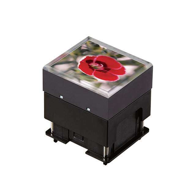
- 型号: ISC15ANP4
- 制造商: NKK Switches
- 库位|库存: xxxx|xxxx
- 要求:
| 数量阶梯 | 香港交货 | 国内含税 |
| +xxxx | $xxxx | ¥xxxx |
查看当月历史价格
查看今年历史价格
ISC15ANP4产品简介:
ICGOO电子元器件商城为您提供ISC15ANP4由NKK Switches设计生产,在icgoo商城现货销售,并且可以通过原厂、代理商等渠道进行代购。 ISC15ANP4价格参考。NKK SwitchesISC15ANP4封装/规格:可编程显示器开关, Programmable Display Switch Pushbutton, OLED SPST-NO 0.1A @ 12VDC Through Hole。您可以下载ISC15ANP4参考资料、Datasheet数据手册功能说明书,资料中有ISC15ANP4 详细功能的应用电路图电压和使用方法及教程。
NKK Switches的ISC15ANP4是一款可编程显示器开关,适用于多种工业和商业应用场景。以下是其主要应用领域:

 1. 工业自动化设备
ISC15ANP4在工业自动化系统中广泛应用,如PLC(可编程逻辑控制器)、HMI(人机界面)等。它可以通过编程实现对设备状态的监控和控制,提供直观的视觉反馈。例如,在生产线上的操作面板上,ISC15ANP4可以显示机器的工作状态、故障信息等,并允许操作员通过按钮进行必要的控制操作。

 2. 医疗设备
在医疗设备中,ISC15ANP4可以用于患者监护仪、心电图机、超声波设备等。它能够清晰地显示设备的工作参数,如心率、血压等,并通过编程设置不同的报警阈值。医生和护士可以通过该开关快速获取关键信息,确保设备正常运行并及时响应异常情况。

 3. 测试与测量仪器
ISC15ANP4在测试与测量仪器中也有广泛应用,如示波器、万用表、信号发生器等。它可以显示仪器的当前设置和测量结果,并允许用户通过编程调整仪器的工作模式。这种功能使得技术人员能够更方便地进行复杂的测试任务,并提高工作效率。

 4. 安防监控系统
在安防监控系统中,ISC15ANP4可以用于视频监控设备的操作面板。它能够显示摄像头的状态、录像进度等信息,并允许用户通过编程设置不同的监控模式。例如,在停车场管理系统中,ISC15ANP4可以帮助管理员实时监控车辆进出情况,并记录相关数据。

 5. 智能家居控制系统
ISC15ANP4还可以应用于智能家居控制系统中,如智能灯光、温控器、门禁系统等。它能够显示设备的工作状态,并通过编程实现远程控制。用户可以通过手机APP或本地控制面板操作ISC15ANP4,实现对家中各种设备的智能化管理。

总之,ISC15ANP4凭借其可编程性和高可靠性,广泛应用于各类需要精确控制和状态显示的场景,为用户提供便捷的操作体验和高效的工作支持。
| 参数 | 数值 |
| 3D型号 | http://www.nkkswitches.com/model.aspx?part=ISC15ANP4&vendor=digikey |
| 产品目录 | |
| 描述 | SWITCH OLED 64RGB X 48 12V可编程开关 OLED SmartSwitch 64 X 48 full color |
| 产品分类 | |
| LED正向电压 | - |
| LED正向电流 | - |
| LED颜色 | - |
| 品牌 | NKK Switches |
| 产品手册 | |
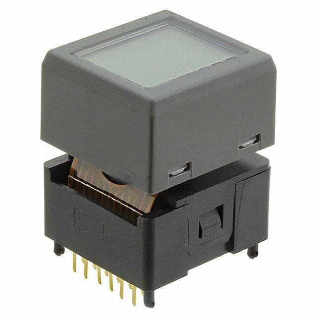
| 产品图片 |
|
| rohs | 符合RoHS无铅 / 符合限制有害物质指令(RoHS)规范要求 |
| 产品系列 | 可编程开关,NKK Switches ISC15ANP4SmartSwitch™ |
| mouser_ship_limit | 该产品可能需要其他文件才能进口到中国。 |
| 数据手册 | |
| 产品型号 | ISC15ANP4 |
| PCN设计/规格 | |
| RoHS指令信息 | |
| 不同电压时的触头额定电流 | 0.1A @ 12VDC |
| 产品培训模块 | http://www.digikey.cn/PTM/IndividualPTM.page?site=cn&lang=zhs&ptm=7079http://www.digikey.cn/PTM/IndividualPTM.page?site=cn&lang=zhs&ptm=25066http://www.digikey.cn/PTM/IndividualPTM.page?site=cn&lang=zhs&ptm=30248http://www.digikey.cn/PTM/IndividualPTM.page?site=cn&lang=zhs&ptm=30298 |
| 产品目录页面 | |
| 产品种类 | 可编程开关 |
| 作用力 | 2.0 牛顿 |
| 像素格式 | 64 x 48 |
| 其它名称 | 360-2344 |
| 包装 | 散装 |
| 可视范围 | 15.5mm 长 x 11.6mm 宽 |
| 商标 | NKK Switches |
| 商标名 | SmartSwitch |
| 安装类型 | 通孔 |
| 安装风格 | Through Hole |
| 工作温度 | -20°C ~ 70°C |
| 工厂包装数量 | 1 |
| 应用说明 | |
| 开关功能 | 关-瞬时 |
| 显示模式 | 65536 颜色,无源矩阵 |
| 标准包装 | 1 |
| 样式 | - |
| 照明 | LED |
| 特色产品 | http://www.digikey.com/cn/zh/ph/NKK/smartswitch_pushbuttons.htmlhttp://www.digikey.com/cn/zh/ph/nkk/oled_switch_display.html |
| 电源电压 | 2.4 ~ 3.5VDC |
| 电路 | SPST-NO |
| 相关产品 | /product-detail/zh/AT9704-085L/360-2346-ND/2039173/product-detail/zh/IS-L02L1-C/IS-L02L1-C-ND/2051130/product-detail/zh/IS-CL01-F-E/360-2424-ND/2187443 |
| 端子类型 | PC 引脚 |
| 端接类型 | Solder Pin |
| 类型 | 按钮,OLED |
| 行程范围 | 4.5mm |
| 表面尺寸 | 23.13mm 长 x 20.59mm 宽 |
| 视频文件 | http://www.digikey.cn/classic/video.aspx?PlayerID=1364138032001&width=640&height=455&videoID=75730281001 |
| 触点形式 | SPST |
| 配用 | /product-detail/zh/IS-DEV%20KIT-7/360-2339-ND/2039166/product-detail/zh/AT9946-091B/360-2423-ND/2187442 |
| 零件号别名 | IS-C15ANP4 |




- 商务部:美国ITC正式对集成电路等产品启动337调查
- 曝三星4nm工艺存在良率问题 高通将骁龙8 Gen1或转产台积电
- 太阳诱电将投资9.5亿元在常州建新厂生产MLCC 预计2023年完工
- 英特尔发布欧洲新工厂建设计划 深化IDM 2.0 战略
- 台积电先进制程称霸业界 有大客户加持明年业绩稳了
- 达到5530亿美元!SIA预计今年全球半导体销售额将创下新高
- 英特尔拟将自动驾驶子公司Mobileye上市 估值或超500亿美元
- 三星加码芯片和SET,合并消费电子和移动部门,撤换高东真等 CEO
- 三星电子宣布重大人事变动 还合并消费电子和移动部门
- 海关总署:前11个月进口集成电路产品价值2.52万亿元 增长14.8%


PDF Datasheet 数据手册内容提取
OLED Pushbutton & Display s e gl DISTINCTIVE CHARACTERISTICS g o T • Organic LED technology • Life 30,000 hours @ 100cd/m2 (based on 40% pixels on) or s er ck • 60,000 hours @ 50cd/m2 (based on 40% pixels on) o R • Power consumption only 3.8mA (30% less than previous product) s • Range of 65,536 colors in 16 bit mode, 256 colors in 8 bit mode n o utt • Full viewing angle of 180° b h us • Exceptional contrast: 50 times greater than LCD products P B • Four times more enhanced resolution P d ate • High resolution provides sharp, clear images of very small characters n mi • Operated by commands and data supplied via serial communications (SPI) u Ill • Distinct, long travel of 4.5mm (same as KP01 series pushbuttons) e bl a m • Dust tight construction m E a gr • Stylish, translucent black housing design o Pr s k c o Viewing area: 15.5mm x 11.6mm (horizontal x vertical) yl e K High reliability and long life of three million actuations s minimum e ari ot R High resolution of 64RGB x 48 pixels s Epoxy sealed straight PC terminals e d Sli Snap-in standoff for easy, secure mounting and alignment s e ctil a T Viewing area: 12.9mm x 9.9mm (horizontal x vertical) High resolution of 52RGB x 36 pixels Tilt Bracket has crimped legs to ensure secure PC mounting and prevent dislodging during wave soldering h c u o T Actual Sizes s or at c di n I s e ori s s e c c A nt e m e Switch Display pl p u S E8 www.nkkswitches.com 10/03/19
OLED Pushbutton ATTENTION es SWITCH PART NUMBER & DESCRIPTION ELECTROSTATIC gl SENSITIVE DEVICES g o T Part Number Switch Description OLED Pixel Format ISC15ANP4 SPSTG, oMldo mCeonnttaarcyts ON DiCspollaoyr OMLoEdDule H6o4rRizGoBnt ax l 4x8 V Peirxtieclasl ckers Straight PC Terminals 65,536 Colors o R SWITCH SPECIFICATIONS s n o Circuit SPST normally open utt b Leave actuator: 1 – 2 OFF h Contact Position Push actuator: 1 – 2 ON Pus Electrical Capacity (Resistive Load) 100mA @ 12V DC B P d Contact Resistance 200 milliohms maximum @ 20mV 10mA e at Insulation Resistance 100 megohms minimum @ 100V DC min Dielectric Strength 125V AC for 1 minute minimum Illu Mechanical Endurance 3,000,000 operations minimum ble a Electrical Endurance 3,000,000 operations minimum E mm Operating Force 2.0 ± 0.5 Newtons gra o Total Travel 4.5mm (.177”) Pr OLED SPECIFICATIONS s k c o Characteristics of Display yl e K Display Device Color OLED display module Display Mode Passive matrix s Viewing Area 15.5mm x 11.6mm (horizontal x vertical) arie Pixel Format 64RGB x 48 pixels (horizontal x vertical) ot R Pixel Size 0.21mm x 0.20mm (horizontal x vertical) Interface Serial (SPI) interface s 65,536 Colors (16bit: R 5bit/G 6bit/B 5bit) e Number of Colors d or 256 Colors (8bit: R 2bit/G 3bit/B 3bit) Sli Operating Temperature Range –20°C ~ +70°C (–4°F ~ +158°F) Storage Temperature Range –30°C ~ +80°C (–22°F ~ +176°F) 30,000 hours @ 100cd/m2 (based on 40% pixels ON) es Operating Life (Display) 60,000 hours @ 50cd/m2 (based on 40% pixels ON) ctil a T Absolute Maximum Ratings Recommended Operating Conditions Items Symbols Ratings Items Symbols Minimum Typical Maximum SLougpipcl/yI nVtoerltfaagcee for VDD –0.3V to +4.0V SLougpipcl/yI nVtoerltfaagcee for VDD 2.4V 2.8V 3.5V Tilt Supply Voltage for Drive V –0.0V to +19.0V Supply Voltage for Drive V 15.0V 16.0V 17.0V CC CC Input Voltage V –0.3V to V +0.3V Input High Level Voltage V 0.8 x V –– –– I DD IH DD h Current Consumption Input Low Level Voltage VIL –– –– 0.2 x VDD Touc (Temperature at 25°C, V = 2.8V, V = 16.0V) Optical Characteristics (Temperature at 25°C, Initial Value: 87 x 0F) DD CC Items SymbolsMin Typical Max Items Min Typical Max Unit Remarks s or *ADllr-iPviex eSlys-sOtenm M Poodwee r Current ICC1 –– 3.8mA 4.6mA Luminosity 75 100 125 cd/m2 (All Wpixheitles on) dicat n All-Pixels-On Mode White Color (x) 0.26 0.30 0.34 –– I *Logic/IF System Power Current IDD1 –– 0.16mA 0.19mA Coordinate (y) 0.32 0.37 0.42 –– s Sleep Mode I –– –– 10μA RCeodo rCdoinloart e ((xy)) 00..6239 00..6373 00..7317 –––– sorie **Drive System Power Current CC2 es Green Color (x) 0.19 0.23 0.27 –– cc Sleep Mode Coordinate (y) 0.61 0.65 0.69 –– A I –– –– 10μA **Logic/IF System Power Current DD2 Blue Color (x) 0.10 0.14 0.18 –– nt * All pixels shall be turned on with the maximum level gray scale Coordinate (y) 0.14 0.20 0.26 –– me e ** All pixels shall be turned off (while chip is operating) Contrast Ratio 100 –– –– –– pl p u S www.nkkswitches.com E9
OLED Pushbutton s e gl SWITCH BLOCK DIAGRAM & PIN CONFIGURATIONS g o T Color OLED Panel 64RGB x 48 SR1,SG1,SB1......SR64, ers SG64,SB64 COM1....COM48 k c o R Segment Driver Common Driver OLED Driver s with Controller n utto VDD 3 SEG/COM hb VCC 9 Driving Block s u P Gray Scale PB Decoder d RES 5 Oscillator e at n Illumi SSCSK 47 G9Dr6aa xtpa h6 i4 c D x i1Rs6Ap lBMaity DisGpelanye rTaimtoirng e SDI 8 bl mma E ISC15ANP4 D/C 6 MCU Interface Command Decoder a gr o GND 10 Pr SW 1 2 SW s k c o Pin No. Symbol Name Function yl e K 1 SW Terminal of Switch Normally open 2 SW Terminal of Switch Normally open es 3 VDD Power Power source for logic circuit ari 4 SS Slave Select Slave select for SPI. This line is active low. ot R Reset signal input. When pin is low, initialization of chip is 5 RES Reset executed. Data/Command Control. When pin is pulled low, data will s 6 D/C Data/Command be interpreted as Command; when pulled high, data will be e Slid interpreted as Data. 7 SCK Serial Clock Clock line for SPI that synchronizes command and data 8 SDI Serial Data In Data input line for SPI 9 V Power Power source for drive circuit es CC ctil 10 GND Ground Connect to Ground a T TYPICAL SWITCH DIMENSIONS Terminal numbers are not on the switch. Tilt SPeixeelDetail (1.532.481) (.313.30) Standoff 1 (.1780.09) Standoff 2 .(002.64)Typ (1.0)Typ .039 (20.59)(.1415.67) (9.3.5777) (.73.6020) 2 10 9 .(27.706) uch .811 (0.4)Typ (.1663.00) 1 4 3 To (0.74) .016 .029 See Standoff Standoff 2 Standoff 1 (15.5) Detail (0.3)Typ (0.2)Typ .610 .012 .008 ators (2.39.1113) (2.930.06) (.313.44) .(83.105) (.72.0785) .(027.09) c di In Pixel Detail Pixel Detail A Standoff Detail Footprint (18.0) 2x (0.9)Dia A .709 .035 s (0.2) (1.0)Typ essorie (.00.02709) Typ ..((000000..02813123)) TTyypp (0.(00.10.2770)9) R .008 (.10.2459) .03(79.0) 9 10 2 (7.62) Acc .0067 RGBR .276 3 4 1 .300 (.1663.00) (0.04) Typ (2.0) Dia 8x (0.75)Dia ent (0.03) Typ .(000.0176) Typ Dimension A .079 .029 m .0012 See Pixel .0028 Standoff 1 = (2.7) Standoff 2 = (2.3) 4x (1.3) Dia e Detail A (0.21) (2.0) (7.05) (8.0) .051 pl .0083 .106 .091 .079 .278 .315 Landless p u S E10 www.nkkswitches.com
OLED Pushbutton & Display s e TIMING SPECIFICATIONS FOR SWITCH & DISPLAY gl g o T AC Characteristics (Temperature at 25°C), V = 2.4V ~ 3.5V) DD Items Symbols Minimum Typical Maximum ers k c o Clock Cycle Time tcycle 150ns –– –– D/C R D/C Setup Time tAS 40ns –– –– tAS tAH ns o D/C Hold Time tAH 40ns –– –– SS tCSS tCSH butt h s u SS Setup Time tCSS 75ns –– –– P tR tCLKH tcycle PB SS Hold Time tCSH 60ns –– –– SCK ed at n Write Data Setup Time tDSW 40ns –– –– tF tCLKL mi u Ill Write Data Hold Time tDHW 40ns –– –– tDSW tDHW e bl SDI D7 D6 D5 D4 D3 D2 D1 D0 ma SCK Low Time tCLKL 75ns –– –– E m a gr SCK High Time tCLKH 75ns –– –– Pro SCK Rise Time tR –– –– 15ns s k c o SCK Fall Time tF –– –– 15ns eyl K STATE TRANSITION s e 7 : Initialization ari ot R State 0 1 : Power ON, 7 : Initialization State 1 3 : Display ON State 2 Power OFF Display OFF Display ON s e (VCC, VDD OFF) 2 : Power OFF (Sleep Mode) 4 : Display OFF d Sli 8 : Changing the Display 8 : Changing the Display s e ctil Power ON/OFF Sequence Ta State Changing the State Display Sleep V V Number CC DD Display Initialization Setting 0 Power OFF OFF –– OFF OFF Disable State 1 State 0 Power ON State 2 Power OFF State 0 Tilt 1 Display OFF OFF ON ON ON Enable Minimum 0µs Minimum 0µs 2 Display ON ON OFF ON ON Enable VDD 0V h c u State Transition Transition Index R(meisneitm louwm p3uµlss)e width Trw To 1 Power ON RES “L” or “Hi-z” “L” or “Hi-z” s 2 Power OFF Refer to ator 3 Display ON "Power ON/OFF Sequence" Minimum 3µs Minimum 0µs dic n I V 4 Display OFF CC s 7 Initialization Initialize Setting of Command/Data D/C VciDrDc uleivt eble (tdwueee tno VEDSDD a pnrdo VteCcCt)ion orie s SS es Image Rewriting Send Display Data SCK “L” or “Hi-z” “H” or “L” “L” or “Hi-z” cc A 8 SDI Display Settings Dimmer, Scroll, etc. nt e m Note: Refer to Application Notes on web site. ple p u S www.nkkswitches.com E13
OLED Pushbutton & Display s e gl PRECAUTIONS FOR HANDLING & STORAGE OF OLED PUSHBUTTONS & DISPLAY g o T ATTENTION Handling ELECTROSTATIC ers SENSITIVE DEVICES k oc 1. The IS Series OLED devices are electrostatic sensitive. To avoid damage to IC, R do not touch terminals unless properly isolated from static electricity. s n 2. Signal input under conditions not recommended may cause damage to the OLED unit or deterioration of the o utt display. Follow directions regarding supply sequences of power and signal voltages. b h s u P 3. If the OLED panel is broken, avoid touching the contents. Wash off any contact to the skin or clothing. B P d 4. Limit operating force to switch keytop to 100.0N maximum, as excessive pressure may damage the OLED. e at n mi 5. For OLED display, it is necessary for bracket legs to be Grounded. u Ill 6. Recommended soldering time and temperature limits for OLED switch or display: e bl a m m E Avoid temperatures exceeding 80°C at the OLED. a gr Wave Soldering: see Profile A in Supplement section. o Pr Manual Soldering: see Profile A in Supplement section. ks 7. The IS series OLED devices are not process sealed. c o yl Ke 8. Pixels acquire diminished brightness over time and use, and those most frequently habituated have greater reduction of brightness than those less used. To minimize this difference, operate OLED unit so that all pixels are used as consistently as possible. s e ari 9. For switch, clean cap surface with dry cloth. If further cleaning is needed, wipe with dampened cloth using ot R neutral cleanser and dry with clean cloth. Do not use organic solvent. For display, avoid contact with any flux or detergent. If any liquids spill on display surface, immediately wipe with soft absorbent cloth. s e d 10. Proper serial resistors and buffers for signals should be used to prevent noise problems. Sli Storage s e ctil 1. Store in original container and away from direct sunlight. a T 2. Keep away from static electricity. 3. Avoid extreme temperatures, high humidity, gaseous substances, and all forms of chemical contamination. Tilt h c u o T s or at c di n I s e ori s s e c c A nt e m e pl p u S E14 www.nkkswitches.com
Optional Accessories s gle OPTIONAL ACCESSORIES g o T AT9704-085K Socket for LCD 64 x 32 Pushbutton Compatible Part Number for AT9704-085K Materials: Long Travel LCD 64 x 32 s cker Base - Glass Fiber Reinforced PBT IS15EBFP4RGB Ro Terminals - Brass/Beryllium Copper s •The socket permits the switch to be plugged in after automated processing. n o utt •Use of the socket enables easy field replacement of the device. b h s u P B P nated (20.3) (7.62) (6.0) (6.0) 9 8 2 (7.62) mi .799 .300 .236 .236 .300 Illuble .(002.50) Dia Typ .(013.09) Typ .(013.09) Typ 3 4 1 9 x (.00.3750) Dia ma (4.6) m E .181 a (22.9) (7.4) (8.0) (7.05) (2.0) (2.0) (7.05) (8.0) gr .902 .291 .315 .278 .079 .079 .278 .315 o Pr ks AT9704-085L Socket for OLED Pushbutton Compatible Part Numbers for AT9704-085L c o yl Materials: OLED Pushbutton Frameless OLED e K Base - Glass Fiber Reinforced PBT ISC15ANP4 ISF15ACP4 Terminals - Brass/Beryllium Copper s e ari •The socket permits the OLED switch to be plugged in after automated processing. ot R •Use of the socket enables easy field replacement of the device. s e d Sli 9 10 2 (20.3) (7.62) (7.0) (7.0) (7.62) .799 .300 .276 .276 3 4 1 .300 es (0.5) Dia Typ (1.0)Typ ctil .020 .039 .(01.309)Typ 1 0 x (.00.3705) Dia a T (4.2) .165 (22.9) (7.0) (8.0) (7.05) (2.0) (2.0) (7.05) (8.0) .902 .276 .315 .278 .079 .079 .278 .315 Tilt AT9704-085M Socket for OLED Display Compatible Part Number for AT9704-085M Materials: OLED Display h Base - Glass Fiber Reinforced PBT ISC01P c u Terminals - Brass/Beryllium Copper o T •The socket permits the OLED display to be plugged in after automated processing. s ator •Use of the socket enables easy field replacement of the device. c di (16.8) n .661 I (16.8) .661 s e sori (17.6) (10.0) (7.0) (7.0) 7 8 (10.0) ces .693 .394 .276 .276 1 2 .394 c A (0.5) DiaTyp (1.0)Typ .020 .039 (1.0)Typ 12x (0.75) Dia nt .039 .030 e (4.4) (5.25) (2.0) m .173 .207 .079 pple (.1798.93) .(278.23) (.72.2855) (5.2.2057) u S E50 www.nkkswitches.com
 Datasheet下载

