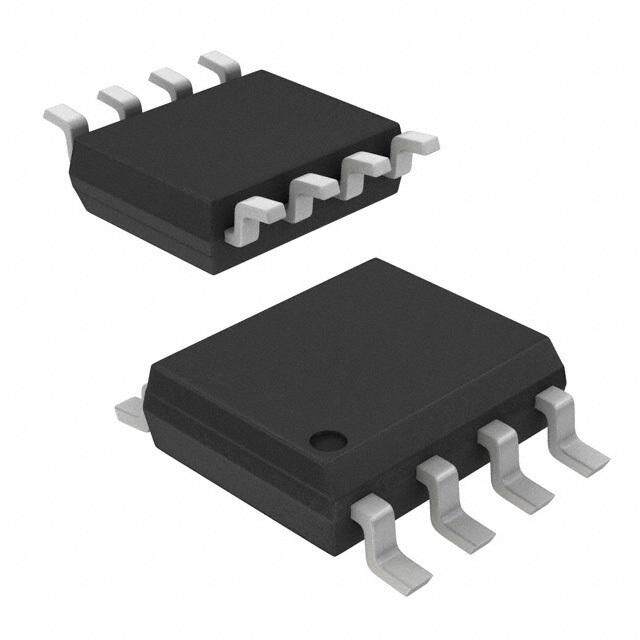
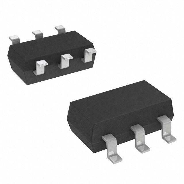
ICGOO在线商城 > 分立半导体产品 > 晶体管 - FET,MOSFET - 单 > IRLML2502GTRPBF
- 型号: IRLML2502GTRPBF
- 制造商: International Rectifier
- 库位|库存: xxxx|xxxx
- 要求:
| 数量阶梯 | 香港交货 | 国内含税 |
| +xxxx | $xxxx | ¥xxxx |
查看当月历史价格
查看今年历史价格
IRLML2502GTRPBF产品简介:
ICGOO电子元器件商城为您提供IRLML2502GTRPBF由International Rectifier设计生产,在icgoo商城现货销售,并且可以通过原厂、代理商等渠道进行代购。 IRLML2502GTRPBF价格参考。International RectifierIRLML2502GTRPBF封装/规格:晶体管 - FET,MOSFET - 单, N-Channel 20V 4.2A (Ta) 1.25W (Ta) Surface Mount Micro3™/SOT-23。您可以下载IRLML2502GTRPBF参考资料、Datasheet数据手册功能说明书,资料中有IRLML2502GTRPBF 详细功能的应用电路图电压和使用方法及教程。
| 参数 | 数值 |
| 产品目录 | |
| 描述 | MOSFET N-CH 20V 4.2A SOT-23-3MOSFET MOSFT 20V 4.2A 45mOhm 8nC Log Lvl |
| 产品分类 | FET - 单分离式半导体 |
| FET功能 | 逻辑电平门 |
| FET类型 | MOSFET N 通道,金属氧化物 |
| Id-ContinuousDrainCurrent | 4.2 A |
| Id-连续漏极电流 | 4.2 A |
| 品牌 | International Rectifier |
| 产品手册 | |
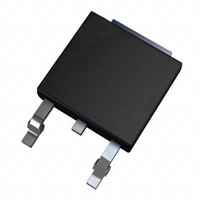
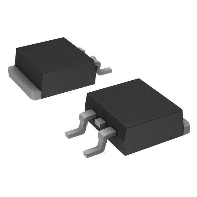
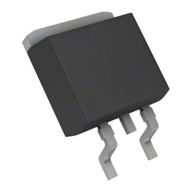
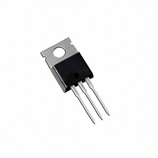
| 产品图片 |
|
| rohs | 符合RoHS无铅 / 符合限制有害物质指令(RoHS)规范要求 |
| 产品系列 | 晶体管,MOSFET,International Rectifier IRLML2502GTRPBFHEXFET® |
| 数据手册 | |
| 产品型号 | IRLML2502GTRPBF |
| Pd-PowerDissipation | 1.25 W |
| Pd-功率耗散 | 1.25 W |
| Qg-GateCharge | 8 nC |
| Qg-栅极电荷 | 8 nC |
| RdsOn-Drain-SourceResistance | 45 mOhms |
| RdsOn-漏源导通电阻 | 45 mOhms |
| Vds-Drain-SourceBreakdownVoltage | 20 V |
| Vds-漏源极击穿电压 | 20 V |
| Vgs-Gate-SourceBreakdownVoltage | 12 V |
| Vgs-栅源极击穿电压 | 12 V |
| 不同Id时的Vgs(th)(最大值) | 1.2V @ 250µA |
| 不同Vds时的输入电容(Ciss) | 740pF @ 15V |
| 不同Vgs时的栅极电荷(Qg) | 12nC @ 5V |
| 不同 Id、Vgs时的 RdsOn(最大值) | 45 毫欧 @ 4.2A,4.5V |
| 产品培训模块 | http://www.digikey.cn/PTM/IndividualPTM.page?site=cn&lang=zhs&ptm=26250http://www.digikey.cn/PTM/IndividualPTM.page?site=cn&lang=zhs&ptm=26240 |
| 产品种类 | MOSFET |
| 供应商器件封装 | Micro3™/SOT-23 |
| 其它名称 | IRLML2502GTRPBFTR |
| 功率-最大值 | 1.25W |
| 功率耗散 | 1.25 W |
| 包装 | 带卷 (TR) |
| 商标 | International Rectifier |
| 安装类型 | 表面贴装 |
| 安装风格 | SMD/SMT |
| 导通电阻 | 45 mOhms |
| 封装 | Reel |
| 封装/外壳 | TO-236-3,SC-59,SOT-23-3 |
| 封装/箱体 | SOT-23-3 |
| 工厂包装数量 | 3000 |
| 晶体管极性 | N-Channel |
| 栅极电荷Qg | 8 nC |
| 标准包装 | 3,000 |
| 汲极/源极击穿电压 | 20 V |
| 漏极连续电流 | 4.2 A |
| 漏源极电压(Vdss) | 20V |
| 电流-连续漏极(Id)(25°C时) | 4.2A (Ta) |
| 闸/源击穿电压 | 12 V |




- 商务部:美国ITC正式对集成电路等产品启动337调查
- 曝三星4nm工艺存在良率问题 高通将骁龙8 Gen1或转产台积电
- 太阳诱电将投资9.5亿元在常州建新厂生产MLCC 预计2023年完工
- 英特尔发布欧洲新工厂建设计划 深化IDM 2.0 战略
- 台积电先进制程称霸业界 有大客户加持明年业绩稳了
- 达到5530亿美元!SIA预计今年全球半导体销售额将创下新高
- 英特尔拟将自动驾驶子公司Mobileye上市 估值或超500亿美元
- 三星加码芯片和SET,合并消费电子和移动部门,撤换高东真等 CEO
- 三星电子宣布重大人事变动 还合并消费电子和移动部门
- 海关总署:前11个月进口集成电路产品价值2.52万亿元 增长14.8%


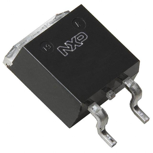
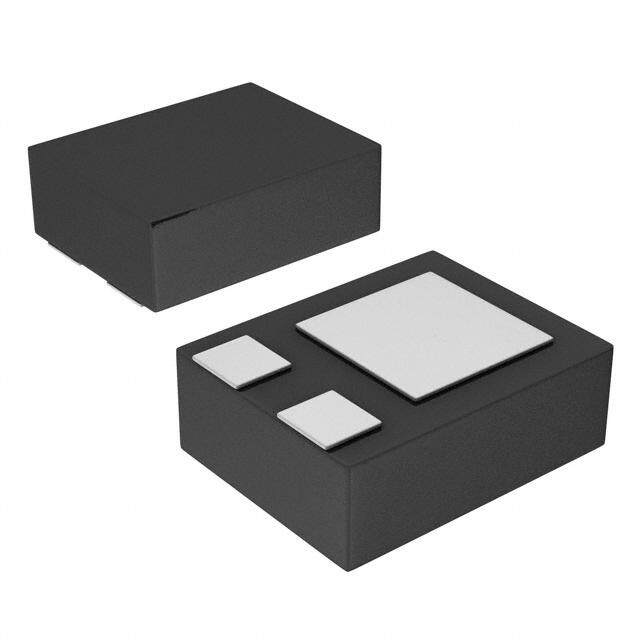
PDF Datasheet 数据手册内容提取
(cid:2)(cid:3)(cid:4)(cid:5)(cid:4)(cid:6)(cid:7)(cid:8)(cid:7)(cid:9)(cid:10) (cid:2)(cid:3)(cid:4)(cid:5)(cid:4)(cid:6)(cid:7)(cid:8)(cid:6)(cid:9)(cid:10)(cid:11)(cid:12) HEXFET(cid:2)(cid:2)Power MOSFET (cid:3) Ultra Low On-Resistance (cid:3) N-Channel MOSFET (cid:3)(cid:4)SOT-23 Footprint G 1 V = 20V (cid:3) Low Profile (<1.1mm) DSS (cid:3) Available in Tape and Reel 3 D (cid:3) Fast Switching RDS(on) = 0.045Ω S 2 (cid:3) Lead-Free (cid:3) Halogen-Free (cid:2)(cid:3)(cid:4)(cid:5)(cid:6)(cid:7)(cid:8)(cid:9)(cid:7)(cid:10)(cid:11) These N-Channel MOSFETs from International Rectifier utilize advanced processing techniques to achieve extremely low on-resistance per silicon area. This benefit, combined with the fast switching speed and ruggedized device design that HEXFET® power MOSFETs are well known for, provides the designer with an extremely efficient and reliable device for use in battery and load management. Micro3™ A thermally enhanced large pad leadframe has been incorporated into the standard SOT-23 package to produce a HEXFET Power MOSFET with the industry's smallest footprint. This package, dubbed the Micro3™, is ideal for applications where printed circuit board space is at a premium. The low profile (<1.1mm) of the Micro3 allows it to fit easily into extremely thin application environments such as portable electronics and PCMCIA cards. The thermal resistance and power dissipation are the best available. (cid:12)(cid:13)(cid:4)(cid:10)(cid:14)(cid:15)(cid:9)(cid:3)(cid:16)(cid:17)(cid:18)(cid:19)(cid:7)(cid:20)(cid:15)(cid:20)(cid:16)(cid:21)(cid:18)(cid:9)(cid:7)(cid:11)(cid:22)(cid:4) Parameter Max. Units VDS Drain- Source Voltage 20 V I @ T = 25°C Continuous Drain Current, V @ 4.5V 4.2 D A GS I @ T = 70°C Continuous Drain Current, V @ 4.5V 3.4 A D A GS I Pulsed Drain Current (cid:5) 33 DM P @T = 25°C Power Dissipation 1.25 D A (cid:5) P @T = 70°C Power Dissipation 0.8 D A Linear Derating Factor 0.01 W/°C V Gate-to-Source Voltage ± 12 V GS TJ, TSTG Junction and Storage Temperature Range -55 to + 150 °C Thermal Resistance Parameter Typ. Max. Units RθJA Maximum Junction-to-Ambient(cid:2) 75 100 (cid:2)(cid:3)(cid:4)(cid:5) www.irf.com 1 09/25/12
(cid:2)(cid:3)(cid:4)(cid:5)(cid:4)(cid:6)(cid:7)(cid:8)(cid:6)(cid:9)(cid:10)(cid:11)(cid:12) Electrical Characteristics @ T = 25°C (unless otherwise specified) J Parameter Min. Typ. Max. Units Conditions V Drain-to-Source Breakdown Voltage 20 ––– ––– V V = 0V, I = 250uA (BR)DSS GS D ΔV /ΔT Breakdown Voltage Temp. Coefficient ––– 0.01 ––– V/°C Reference to 25°C, I = 1.0mA (BR)DSS J D R Static Drain-to-Source On-Resistance ––– 0.035 0.045 Ω V = 4.5V, I = 4.2A (cid:3) DS(on) GS D ––– 0.050 0.080 V = 2.5V, I = 3.6A (cid:3) GS D V Gate Threshold Voltage 0.60 ––– 1.2 V GS(th) V = V , I = 250μA ΔV Gate Threshold Voltage Coefficient ––– -3.2 ––– mV/°C DS GS D GS(th) gfs Forward Transconductance 5.8 ––– ––– S V = 10V, I = 4.0A DS D I Drain-to-Source Leakage Current ––– ––– 1.0 V = 16V, V = 0V DSS μA DS GS ––– ––– 25 V = 16V, V = 0V, T = 70°C DS GS J I Gate-to-Source Forward Leakage ––– ––– 100 V = 12V GSS nA GS Gate-to-Source Reverse Leakage ––– ––– -100 V = -12V GS Q Total Gate Charge ––– 8.0 12 I = 4.0A g D Q Gate-to-Source Charge ––– 1.8 2.7 nC V = 10V gs DS Q Gate-to-Drain ("Miller") Charge ––– 1.7 2.6 V = 5.0V (cid:3) gd GS t Turn-On Delay Time ––– 7.5 ––– V = 10V d(on) DD t Rise Time ––– 10 ––– I = 1.0A r ns D t Turn-Off Delay Time ––– 54 ––– R = 6Ω d(off) G t Fall Time ––– 26 ––– R = 10Ω (cid:3) f D C Input Capacitance ––– 740 ––– V = 0V iss GS C Output Capacitance ––– 90 ––– pF V = 15V oss DS C Reverse Transfer Capacitance ––– 66 ––– ƒ = 1.0MHz rss Source-Drain Rating and Characteristics Parameter Min. Typ. Max. Units Conditions IS Continuous Source Current ––– ––– 1.3 MOSFET symbol D (Body Diode) showing the A ISM Pulsed Source Current ––– ––– 33 integral reverse G (Body Diode)(cid:0)(cid:2) p-n junction diode. S V Diode Forward Voltage ––– ––– 1.2 V T = 25°C, I = 1.3A, V = 0V (cid:3) SD J S GS t Reverse Recovery Time ––– 16 24 ns T = 25°C, I = 1.3A rr J F Q Reverse Recovery Charge ––– 8.6 13 nC di/dt = 100A/μs (cid:3)(cid:0) rr (cid:2)(cid:3)(cid:4)(cid:5)(cid:6)(cid:7) (cid:2)(cid:6)Repetitive rating; pulse width limited by (cid:4)(cid:6)(cid:6)Surface mounted on FR-4 board, t(cid:6)≤ (cid:10)(cid:11)(cid:12)(cid:13)(cid:9) max. junction temperature. ( See fig. 11 ) (cid:3)(cid:6)Pulse width(cid:6)≤ 300μs; duty cycle ≤(cid:6)(cid:7)(cid:8)(cid:9) 2 www.irf.com
(cid:2)(cid:3)(cid:4)(cid:5)(cid:4)(cid:6)(cid:7)(cid:8)(cid:6)(cid:9)(cid:10)(cid:11)(cid:12) 100 100 VGS VGS TOP 7.00V TOP 7.00V 5.00V 5.00V A) 43..5500VV A) 43..5500VV nt ( 32..0700VV nt ( 32..0700VV e 2.50V e 2.50V urr BOTTOM2.25V urr BOTTOM2.25V C C e e c 2.25V c ur ur 2.25V o 10 o 10 S S o- o- n-t n-t ai ai Dr Dr I , D I , D 20μs PULSE WIDTH 20μs PULSE WIDTH TJ = 25°C TJ = 150°C 1 1 0.1 1 10 100 0.1 1 10 100 V , Drain-to-Source Voltage (V) V , Drain-to-Source Voltage (V) DS DS Fig 1. Typical Output Characteristics Fig 2. Typical Output Characteristics 100 2.0 ID=4.0A e c n urrent (A) n Resista 1.5 e C e Oed) c cz our TJ = 25 ° C ourmali 1.0 S S n-to- n-to-(Nor Drai TJ = 150 ° C Drai 0.5 I , D V20 D μ Ss =P U15LVSE WIDTH R , DS(on) VGS=4.5V 10 0.0 2.0 2.4 2.8 3.2 3.6 4.0 -60 -40 -20 0 20 40 60 80 100 120 140 160 VG S , Gate-to-Source Voltage (V) TJ , Junction Temperature ( ° C) Fig 3. Typical Transfer Characteristics Fig 4. Normalized On-Resistance Vs. Temperature www.irf.com 3
(cid:2)(cid:3)(cid:4)(cid:5)(cid:4)(cid:6)(cid:7)(cid:8)(cid:6)(cid:9)(cid:10)(cid:11)(cid:12) 1200 10 VGS=0V, f = 1MHz ID=4.0A CCirssss ==CCggsd+ Cgd , Cd s SHORTED V) VDS= 10V 1000 Coss=Cds + Cgd e ( 8 g ance (pF) 800 Ciss urce Volta 6 cit 600 So pa o- Ca e-t 4 C, 400 Gat 200 Coss V , GS 2 Crss 0 0 1 10 100 0 4 8 12 16 V D S , Drain-to-Source Voltage (V) Q G , Total Gate Charge (nC) Fig 5. Typical Capacitance Vs. Fig 6. Typical Gate Charge Vs. Drain-to-Source Voltage Gate-to-Source Voltage 100 1000 OPERATION IN THIS AREA LIMITED BY RDS(on) A) ent ( A)A) 100 ain Curr 10 TJ = 150 ° C urrent (urrent ( 10us erse Dr Drain CDrain C 10 100us I , RevSD 1 TJ = 25 ° C I , I , D 1 TA= 25 ° C 11m0mss T = 150 ° C J 0.1 V G S = 0 V 0.1 Single Pulse 0.4 0.6 0.8 1.0 1.2 1.4 0.1 1 10 100 V S D ,Source-to-Drain Voltage (V) VD S , Drain-to-Source Voltage (V) Fig 7. Typical Source-Drain Diode Fig 8. Maximum Safe Operating Area Forward Voltage 4 www.irf.com
(cid:2)(cid:3)(cid:4)(cid:5)(cid:4)(cid:6)(cid:7)(cid:8)(cid:6)(cid:9)(cid:10)(cid:11)(cid:12) 4.0 3.0 A) nt ( e urr C 2.0 n ai Dr I , D1.0 0.0 25 50 75 100 125 150 T , Case Temperature ( ° C) C Fig 9. Maximum Drain Current Vs. Case Temperature 1000 ) Z thJA 100 D = 0.50 ( e s 0.20 n po 10 0.10 s e 0.05 R al 0.02 PDM rm 0.01 t1 he 1 SINGLE PULSE t2 T (THERMAL RESPONSE) Notes: 1. Duty factor D = t 1 / t2 2. Peak TJ=PDMx ZthJA+ TA 0.1 0.00001 0.0001 0.001 0.01 0.1 1 10 t , Rectangular Pulse Duration (sec) 1 Fig 10. Maximum Effective Transient Thermal Impedance, Junction-to-Ambient www.irf.com 5
(cid:2)(cid:3)(cid:4)(cid:5)(cid:4)(cid:6)(cid:7)(cid:8)(cid:6)(cid:9)(cid:10)(cid:11)(cid:12) 0.05 Ω) 0.30 Ω) e ( e( anc oagtl essit VGS = 2.5V Ve 0.04 Rn 0.20 c O ur e o c Sno--t Id = 4.0A Soou-r Dar , in) 0.03 Dan, r-it 0.10 VGS = 4.5V So( n) RD So ( 0.02 D 0.00 R 2.0 2.5 3.0 3.5 4.0 4.5 5.0 5.5 6.0 6.5 7.0 0 10 20 30 40 VGS, Gate -to -Source Voltage ( V ) iD , Drain Current ( A ) Fig 11. On-Resistance Vs. Gate Voltage Fig 12. On-Resistance Vs. Drain Current 1.3 V) e( g a 1.1 otl V d ol h s e 0.9 hr et at G ,h) 0.7 S(t ID = 50μA G ID = 250μA V 0.5 -75 -50 -25 0 25 50 75 100 125 150 TJ , Temperature ( °C ) Fig 13. Threshold Voltage Vs. Temperature 6 www.irf.com
(cid:2)(cid:3)(cid:4)(cid:5)(cid:4)(cid:6)(cid:7)(cid:8)(cid:6)(cid:9)(cid:10)(cid:11)(cid:12) (cid:2)(cid:3)(cid:4)(cid:5)(cid:6)(cid:7)(cid:8)(cid:9)(cid:10)(cid:11)(cid:12)(cid:13)(cid:14)(cid:7)(cid:15)(cid:8)(cid:16)(cid:17)(cid:4)(cid:18)(cid:17)(cid:19)(cid:20)(cid:8)(cid:11)(cid:21)(cid:22)(cid:23)(cid:3)(cid:24)(cid:20) (cid:3)(cid:4)(cid:5)(cid:6)(cid:7)(cid:8)(cid:4)(cid:9)(cid:7)(cid:8)(cid:10)(cid:11)(cid:12)(cid:6)(cid:10)(cid:8)(cid:13)(cid:9)(cid:14)(cid:7)(cid:10)(cid:4)(cid:7)(cid:10)(cid:5)(cid:4)(cid:15)(cid:15)(cid:4)(cid:5)(cid:6)(cid:16)(cid:6)(cid:12)(cid:8)(cid:10)(cid:17)(cid:4)(cid:7)(cid:18)(cid:13)(cid:6)(cid:8)(cid:19) DIMENSIONS 6 A 5 MILLIMETERS INCHES D SYMBOL MIN MAX MIN MAX A 0.89 1.12 (cid:0)(cid:2)(cid:0)(cid:12)(cid:10) (cid:0)(cid:2)(cid:0)(cid:11)(cid:11) A A1 0.01 0.10 0.0004 (cid:0)(cid:2)(cid:0)(cid:0)(cid:11) A2 C 3 E A2 0.88 1.02 (cid:0)(cid:2)(cid:0)(cid:12)(cid:10) (cid:0)(cid:2)(cid:0)(cid:11)(cid:0) 6 E1 1 2 0.15 [0.006]MCBA 0.10 [0.004]C bc 00..3008 00..5200 (cid:0)(cid:0)(cid:2)(cid:2)(cid:0)(cid:0)(cid:0)(cid:3)(cid:12)(cid:4) (cid:0)(cid:0)(cid:2)(cid:2)(cid:0)(cid:0)(cid:0)(cid:4)(cid:14)(cid:0) A1 3Xb D 2.80 3.04 (cid:0)(cid:2)(cid:3)(cid:3)(cid:0) (cid:0)(cid:2)(cid:3)(cid:4)(cid:0) 5 B e 0.20 [0.008]MCBA E 2.10 2.64 (cid:0)(cid:2)(cid:0)(cid:14)(cid:12) (cid:0)(cid:2)(cid:3)(cid:0)(cid:11) e1 NOTES: E1 1.20 1.40 (cid:0)(cid:2)(cid:0)(cid:11)(cid:9) (cid:0)(cid:2)(cid:0)(cid:10)(cid:10) e 0.95 BSC (cid:0)(cid:2)(cid:0)(cid:12)(cid:9) (cid:5)(cid:6)(cid:7) e1 1.90 BSC (cid:0)(cid:2)(cid:0)(cid:9)(cid:10) (cid:5)(cid:6)(cid:7)(cid:8) L 0.40 0.60 (cid:0)(cid:2)(cid:0)(cid:3)(cid:13) (cid:0)(cid:2)(cid:0)(cid:4)(cid:11) H 4 L1 Recommended Footprint L1 0.54 REF (cid:0)(cid:2)(cid:0)(cid:4)(cid:3) REF L2 0.25 BSC (cid:0)(cid:2)(cid:0)(cid:3)(cid:0) BSC c 0 8 0 8 0.972 L2 0.802 0.950 2.742 3X L 1. DIMENSIONING & TOLERANCING PER ANSI Y14.5M-1994 2. DIMENSIONS ARE SHOWN IN MILLIMETERS [INCHES]. 7 3. CONTROLLING DIMENSION: MILLIMETER. 4. DATUM PLANE H IS LOCATED AT THE MOLD PARTING LINE. 1.900 5. DATUM A AND B TO BE DETERMINED AT DATUM PLANE H. 6. DIMENSIONS D AND E1 ARE MEASURED AT DATUM PLANE H. DIMENSIONS DOES NOT INCLUDE MOLD PROTRUSIONS OR INTERLEAD FLASH. MOLD PROTRUSIONS OR INTERLEAD FLASH SHALL NOT EXCEED 0.25 MM [0.010 INCH] PER SIDE. 7. DIMENSION L IS THE LEAD LENGTH FOR SOLDERING TO A SUBSTRATE. 8. OUTLINE CONFORMS TO JEDEC OUTLINE TO-236 AB. Micro3 (SOT-23/TO-236AB) Part Marking Information Notes: This part marking information applies to devices produced after 02/26/2001 W = (1-26) IF PRECEDED BY LAST DIGIT OF CALENDAR YEAR DATE CODE PART NUMBER LEAD FREE YEAR Y WWEOERKK W 2001 1 01 A 2002 2 02 B 2003 3 03 C 2004 4 04 D Cu WIRE LOT CODE 2005 5 HALOGEN FREE 2006 6 X = PART NUMBER CODE REFERENCE: 2007 7 A = IRLML2402 2008 8 2009 9 B = IRLML2803 2010 0 24 X C = IRLML6302 25 Y D = IRLML5103 26 Z E = IRLML6402 F = IRLML6401 W = (27-52) IF PRECEDED BY A LETTER G = IRLML2502 WORK H = IRLML5203 YEAR Y WEEK W I = IRLML0030 2001 A 27 A J = IRLML2030 2002 B 28 B K = IRLML0100 2003 C 29 C 2004 D 30 D L = IRLML0060 2005 E M = IRLML0040 2006 F N = IRLML2060 2007 G P = IRLML9301 2008 H R = IRLML9303 2009 J 2010 K 50 X Note: For the most current drawing please refer to IR website at: http://www.irf.com/package/ www.irf.com 7
(cid:2)(cid:3)(cid:4)(cid:5)(cid:4)(cid:6)(cid:7)(cid:8)(cid:6)(cid:9)(cid:10)(cid:11)(cid:12) (cid:2)(cid:3)(cid:4)(cid:5)(cid:6)(cid:7)™ (cid:12)(cid:17)(cid:25)(cid:20)(cid:8)(cid:26)(cid:8)(cid:27)(cid:20)(cid:20)(cid:23)(cid:8)(cid:28)(cid:24)(cid:29)(cid:6)(cid:5)(cid:30)(cid:17)(cid:22)(cid:3)(cid:6)(cid:24) (cid:3)(cid:4)(cid:5)(cid:6)(cid:7)(cid:8)(cid:4)(cid:9)(cid:7)(cid:8)(cid:10)(cid:11)(cid:12)(cid:6)(cid:10)(cid:8)(cid:13)(cid:9)(cid:14)(cid:7)(cid:10)(cid:4)(cid:7)(cid:10)(cid:5)(cid:4)(cid:15)(cid:15)(cid:4)(cid:5)(cid:6)(cid:16)(cid:6)(cid:12)(cid:8)(cid:10)(cid:17)(cid:4)(cid:7)(cid:18)(cid:13)(cid:6)(cid:8)(cid:19) 2.05 ( .080 ) 1.6 ( .062 ) 1.32 ( .051 ) 1.95 ( .077 ) 4.1 ( .161 ) 1.5 ( .060 ) 1.85 ( .072 ) 1.12 ( .045 ) 3.9 ( .154 ) 1.65 ( .065 ) TR 3.55 ( .139 ) 8.3 ( .326 ) 3.45 ( .136 ) 7.9 ( .312 ) FEED DIRECTION 4.1 ( .161 ) 3.9 ( .154 ) 1.1 ( .043 ) 0.35 ( .013 ) 0.9 ( .036 ) 0.25 ( .010 ) 178.00 ( 7.008 ) MAX. 9.90 ( .390 ) 8.40 ( .331 ) NOTES: 1. CONTROLLING DIMENSION : MILLIMETER. 2. OUTLINE CONFORMS TO EIA-481 & EIA-541. Note: For the most current drawing please refer to IR website at http://www.irf.com/package Data and specifications subject to change without notice. IR WORLD HEADQUARTERS: 101N.Sepulveda blvd, El Segundo, California 90245, USA Tel: (310) 252-7105 TAC Fax: (310) 252-7903 Visit us at www.irf.com for sales contact information. 09/2012 8 www.irf.com
Mouser Electronics Authorized Distributor Click to View Pricing, Inventory, Delivery & Lifecycle Information: I nfineon: IRLML2502GTRPBF
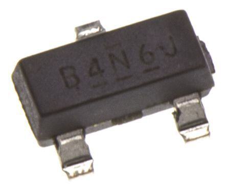
 Datasheet下载

