ICGOO在线商城 > 集成电路(IC) > PMIC - 稳流/电流管理 > INA216A2YFFT
- 型号: INA216A2YFFT
- 制造商: Texas Instruments
- 库位|库存: xxxx|xxxx
- 要求:
| 数量阶梯 | 香港交货 | 国内含税 |
| +xxxx | $xxxx | ¥xxxx |
查看当月历史价格
查看今年历史价格
INA216A2YFFT产品简介:
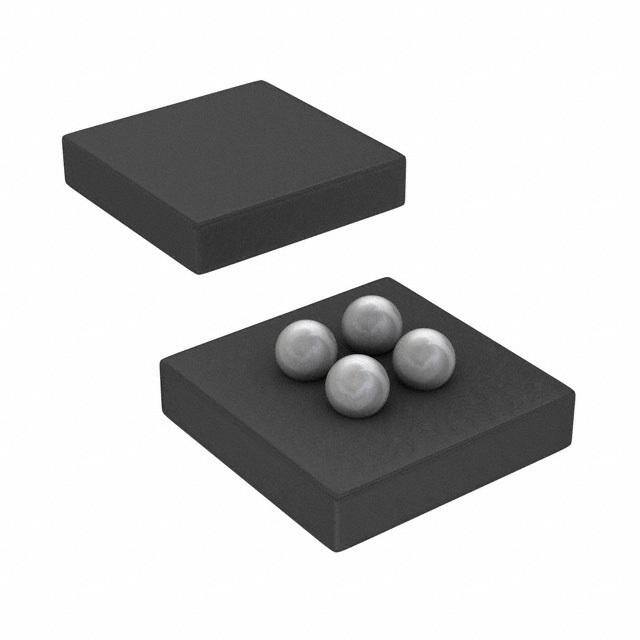
ICGOO电子元器件商城为您提供INA216A2YFFT由Texas Instruments设计生产,在icgoo商城现货销售,并且可以通过原厂、代理商等渠道进行代购。 INA216A2YFFT价格参考。Texas InstrumentsINA216A2YFFT封装/规格:PMIC - 稳流/电流管理, Current Monitor Regulator High-Side 4-DSBGA (1x1)。您可以下载INA216A2YFFT参考资料、Datasheet数据手册功能说明书,资料中有INA216A2YFFT 详细功能的应用电路图电压和使用方法及教程。
| 参数 | 数值 |
| 产品目录 | 集成电路 (IC)半导体 |
| 描述 | IC CURRENT SHUNT MONITOR 4DSBGA电流和电力监控器、调节器 Tiny,Low Pwr Current Sense Amp |
| 产品分类 | |
| 品牌 | Texas Instruments |
| 产品手册 | |
| 产品图片 |
|
| rohs | 符合RoHS无铅 / 符合限制有害物质指令(RoHS)规范要求 |
| 产品系列 | 电源管理 IC,电流和电力监控器、调节器,Texas Instruments INA216A2YFFT零漂移 |
| 数据手册 | 点击此处下载产品Datasheethttp://www.ti.com/lit/pdf/slyb174 |
| 产品型号 | INA216A2YFFT |
| 产品 | Current Monitors |
| 产品种类 | 电流和电力监控器、调节器 |
| 供应商器件封装 | 4-DSBGA(1x1) |
| 其它名称 | 296-32099-6 |
| 准确性 | +/- 2 % |
| 制造商产品页 | http://www.ti.com/general/docs/suppproductinfo.tsp?distId=10&orderablePartNumber=INA216A2YFFT |
| 功能 | 电流监控器 |
| 包装 | Digi-Reel® |
| 商标 | Texas Instruments |
| 安装类型 | 表面贴装 |
| 安装风格 | SMD/SMT |
| 封装 | Reel |
| 封装/外壳 | 4-UFBGA,DSBGA |
| 封装/箱体 | DSBGA-4 |
| 工作温度 | -40°C ~ 125°C |
| 工作温度范围 | - 40 C to + 125 C |
| 工厂包装数量 | 250 |
| 感应方式 | High Side |
| 感应方法 | 高端 |
| 标准包装 | 1 |
| 电压-输入 | 1.8 V ~ 5.5 V |
| 电流-输出 | - |
| 电源电压-最大 | 5.5 V |
| 电源电压-最小 | 1.8 V |
| 电源电流 | 0.03 mA |
| 精度 | ±0.5% |
| 系列 | INA216A2 |
| 输入电压范围 | 1.8 V to 5.5 V |


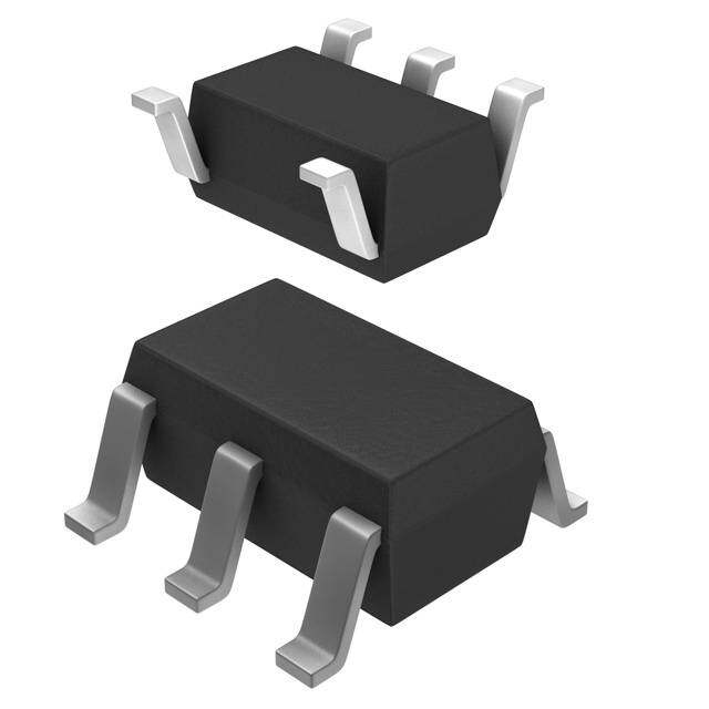
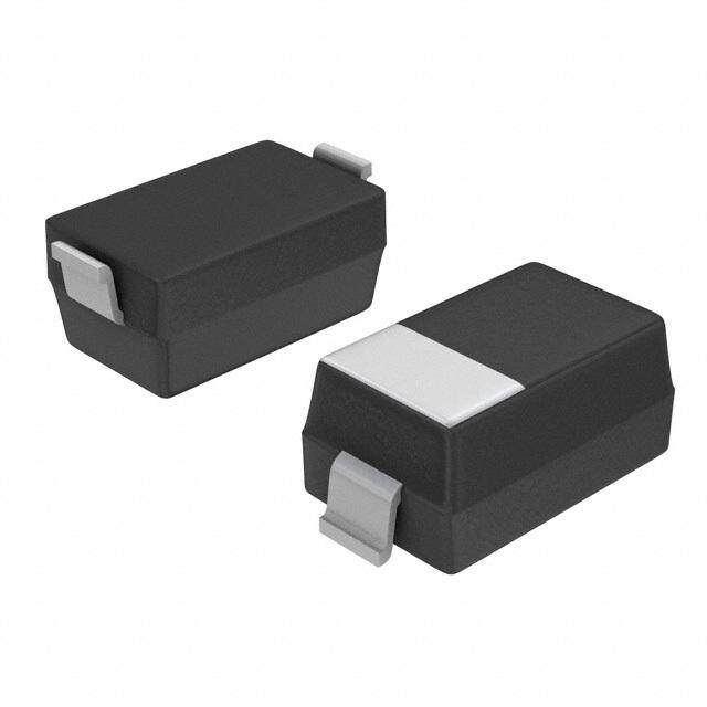


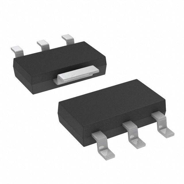

- 商务部:美国ITC正式对集成电路等产品启动337调查
- 曝三星4nm工艺存在良率问题 高通将骁龙8 Gen1或转产台积电
- 太阳诱电将投资9.5亿元在常州建新厂生产MLCC 预计2023年完工
- 英特尔发布欧洲新工厂建设计划 深化IDM 2.0 战略
- 台积电先进制程称霸业界 有大客户加持明年业绩稳了
- 达到5530亿美元!SIA预计今年全球半导体销售额将创下新高
- 英特尔拟将自动驾驶子公司Mobileye上市 估值或超500亿美元
- 三星加码芯片和SET,合并消费电子和移动部门,撤换高东真等 CEO
- 三星电子宣布重大人事变动 还合并消费电子和移动部门
- 海关总署:前11个月进口集成电路产品价值2.52万亿元 增长14.8%
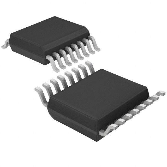

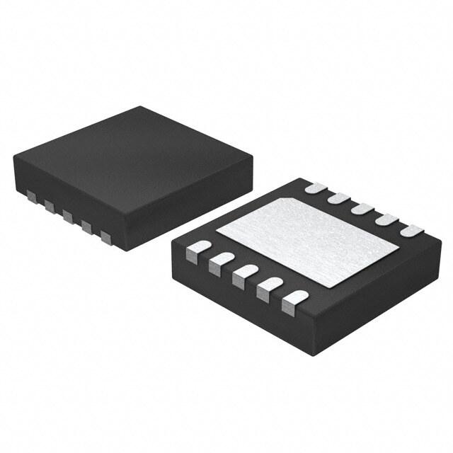

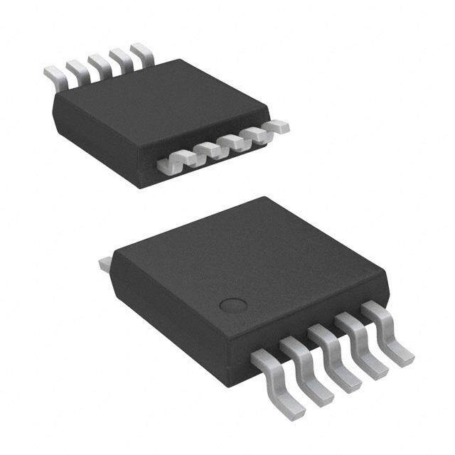

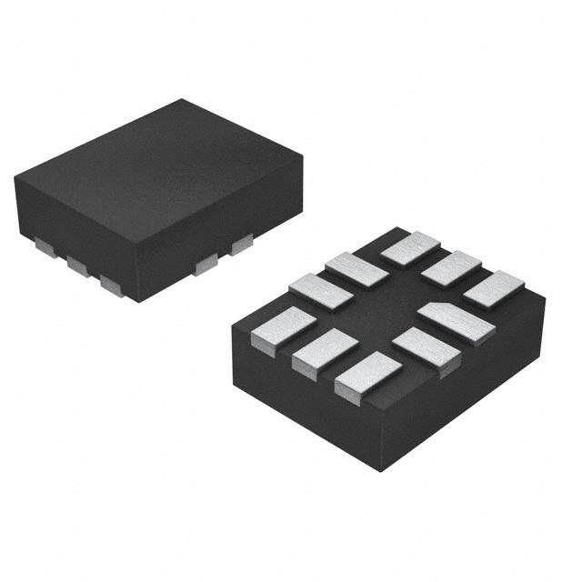
PDF Datasheet 数据手册内容提取
INA216 www.ti.com SBOS503C–JUNE2010–REVISEDNOVEMBER2011 Small Size, Low-Power, Unidirectional, CURRENT SHUNT MONITOR Zerø-Drift Series CheckforSamples:INA216 FEATURES DESCRIPTION 1 • CHIP-SCALEPACKAGE The INA216 is a high-side voltage output current 2 shunt monitor that can sense drops across shunts at • COMMON-MODERANGE:+1.8Vto+5.5V common-mode voltages from +1.8V to +5.5V. Four • OFFSETVOLTAGE:±30μV fixed gains are available: 25V/V, 50V/V, 100V/V, and • GAINERROR:±0.2%MAX 200V/V. The low offset of the Zerø-Drift architecture enables current sensing with maximum drops across • CHOICEOFGAINS: the shunt as low as 10mV full-scale, or with wide – INA216A1:25V/V dynamicrangesofover1000:1. – INA216A2:50V/V These devices operate from a single +1.8V to +5.5V – INA216A3:100V/V power supply, drawing a maximum of 25μA of supply – INA216A4:200V/V current. The INA216 series are specified over the temperature range of –40°C to +125°C, and offered • QUIESCENTCURRENT:13μA inachip-scalepackage. • BUFFEREDVOLTAGEOUTPUT:NoAdditional OpAmpNeeded Shunt Supply: Load +1.8V to +5.5V APPLICATIONS • NOTEBOOKCOMPUTERS • CELLPHONES R1 R2 IN+ IN- • TELECOMEQUIPMENT • POWERMANAGEMENT • BATTERYCHARGERS 1.6MW 1.6MW GND OUT PRODUCT GAIN R = R 1 2 INA216A1 25 64kW INA216A2 50 32kW INA216A3 100 16kW INA216A4 200 8kW 1 Pleasebeawarethatanimportantnoticeconcerningavailability,standardwarranty,anduseincriticalapplicationsofTexas Instrumentssemiconductorproductsanddisclaimerstheretoappearsattheendofthisdatasheet. Alltrademarksarethepropertyoftheirrespectiveowners. 2 PRODUCTIONDATAinformationiscurrentasofpublicationdate. Copyright©2010–2011,TexasInstrumentsIncorporated Products conform to specifications per the terms of the Texas Instruments standard warranty. Production processing does not necessarilyincludetestingofallparameters.
INA216 SBOS503C–JUNE2010–REVISEDNOVEMBER2011 www.ti.com This integrated circuit can be damaged by ESD. Texas Instruments recommends that all integrated circuits be handled with appropriateprecautions.Failuretoobserveproperhandlingandinstallationprocedurescancausedamage. ESDdamagecanrangefromsubtleperformancedegradationtocompletedevicefailure.Precisionintegratedcircuitsmaybemore susceptibletodamagebecauseverysmallparametricchangescouldcausethedevicenottomeetitspublishedspecifications. PACKAGEINFORMATION(1) PACKAGE PRODUCT GAIN PACKAGE-LEAD DESIGNATOR PACKAGEMARKING WCSP-4 YFF OW INA216A1 25V/V ThinQFN-10 RSW SNJ WCSP-4 YFF OX INA216A2 50V/V ThinQFN-10 RSW SOJ WCSP-4 YFF OY INA216A3 100V/V ThinQFN-10 RSW SPJ WCSP-4 YFF OZ INA216A4 200V/V ThinQFN-10 RSW SQJ (1) ForthemostcurrentpackageandorderinginformationseethePackageOptionAddendumattheendofthisdocument,orvisitthe deviceproductfolderatwww.ti.com. ABSOLUTE MAXIMUM RATINGS(1) Overoperatingfree-airtemperaturerange,unlessotherwisenoted. INA216 UNIT SupplyVoltage +7 V AnalogInputs, Differential(VIN+)–(VIN–) –5.5to+5.5 V VIN+,VIN–(2) Common-Mode(3) GND–0.3Vto+5.5 V Output(3) GND–0.3Vto(V+)+0.3 V InputCurrentintoAnyPin(3) 5 mA OperatingTemperature –55to+150 °C StorageTemperature –65to+150 °C JunctionTemperature +150 °C HumanBodyModel 2.5 kV ESDRatings: ChargedDeviceModel 1 kV MachineModel 200 V (1) Stressesabovetheseratingsmaycausepermanentdamage.Exposuretoabsolutemaximumconditionsforextendedperiodsmay degradedevicereliability.Thesearestressratingsonly,andfunctionaloperationofthedeviceattheseoranyotherconditionsbeyond thosespecifiedisnotimplied. (2) V andV arethevoltagesattheIN+andIN–pins,respectively. IN+ IN– (3) Inputvoltageatanypinmayexceedthevoltageshownifthecurrentatthatpinislimitedto5mA. 2 SubmitDocumentationFeedback Copyright©2010–2011,TexasInstrumentsIncorporated ProductFolderLink(s):INA216
INA216 www.ti.com SBOS503C–JUNE2010–REVISEDNOVEMBER2011 THERMAL INFORMATION INA216A1YFF, INA216A2YFF INA216A3YFF, THERMALMETRIC(1) INA216A4YFF UNITS YFF 4PINS θ Junction-to-ambientthermalresistance 160 JA θ Junction-to-case(top)thermalresistance 75 JC(top) θ Junction-to-boardthermalresistance 76 JB °C/W ψ Junction-to-topcharacterizationparameter 3 JT ψ Junction-to-boardcharacterizationparameter 74 JB θ Junction-to-case(bottom)thermalresistance n/a JC(bottom) (1) Formoreinformationabouttraditionalandnewthermalmetrics,seetheICPackageThermalMetricsapplicationreport,SPRA953. THERMAL INFORMATION INA216A1RSW, INA216A2RSW INA216A3RSW, THERMALMETRIC(1) INA216A4RSW UNITS RSW 10PINS θ Junction-to-ambientthermalresistance 114.9 JA θ Junction-to-case(top)thermalresistance 66.3 JC(top) θ Junction-to-boardthermalresistance 21.4 JB °C/W ψ Junction-to-topcharacterizationparameter 1.9 JT ψ Junction-to-boardcharacterizationparameter 21.4 JB θ Junction-to-case(bottom)thermalresistance N/A JC(bottom) (1) Formoreinformationabouttraditionalandnewthermalmetrics,seetheICPackageThermalMetricsapplicationreport,SPRA953. PIN CONFIGURATIONS RSWPACKAGE ThinQFN-10 YFFPACKAGE (TOPVIEW) WCSP-4 (TOPVIEW) (1) (1) NC NC A2 B2 IN- OUT (1) 7 6 NC 8 5 IN- A1 B1 IN+ GND GND 9 4 IN- (2) Bumpsidedown.Drawingnottoscale. OUT 10 3 IN+ 1 2 (3) Power supply is derived from shunt (minimumcommon-moderange=1.8V) (1) NC IN+ (1) Nointernalconnection. Copyright©2010–2011,TexasInstrumentsIncorporated SubmitDocumentationFeedback 3 ProductFolderLink(s):INA216
INA216 SBOS503C–JUNE2010–REVISEDNOVEMBER2011 www.ti.com ELECTRICAL CHARACTERISTICS Boldfacelimitsapplyoverthespecifiedtemperaturerange,T =–40°Cto+125°C. A AtT =+25°CandV =V =4.2V,unlessotherwisenoted. A CM IN+ INA216 PARAMETER CONDITIONS MIN TYP MAX UNIT INPUT OffsetVoltage,RTI(1) VOS INA216A1 ±30 ±100 μV vsTemperature dVOS/dT 0.06 0.2 μV/°C INA216A2 ±20 ±75 μV vsTemperature dVOS/dT 0.05 0.25 μV/°C INA216A3 ±20 ±75 μV vsTemperature dVOS/dT 0.03 0.25 μV/°C INA216A4 ±20 ±75 μV vsTemperature dVOS/dT 0.1 0.3 μV/°C Common-ModeInputRange VCM 1.8 5.5 V Common-ModeRejection(2) CMRR VIN+=+1.8Vto+5.5V 90 108 dB Power-SupplyRejection PSRR 90 108 dB InputBiasCurrent IIN– 3 μA OUTPUT Gain G INA216A1 25 V/V INA216A2 50 V/V INA216A3 100 V/V INA216A4 200 V/V GainError INA216A1 VOUT=0.2VtoVOUT=2.5V ±0.01 ±0.2 % vsTemperature VOUT=0.2VtoVOUT=2.5V 0.01 0.025 m%/°C INA216A2 0.05 ±0.2 % vsTemperature 0.017 0.1 m%/°C INA216A3 0.06 ±0.2 % vsTemperature 0.023 0.1 m%/°C INA216A4 0.03 ±0.2 % vsTemperature 0.076 0.3 m%/°C NonlinearityError ±0.01 % MaximumCapacitiveLoad Nosustainedoscillation 750 pF VOLTAGEOUTPUT(3) RL=10kΩtoGND SwingtoV+Power-SupplyRail (V+)–0.1 (V+)–0.3 V SwingtoGND(3) (VGND)+0.001 (VGND)+0.002 V OutputImpedance 42 Ω FREQUENCYRESPONSE Bandwidth BW CLOAD=10pF INA216A1 20 kHz INA216A2 10 kHz INA216A3 5 kHz INA216A4 2.5 kHz (1) RTI:Referred-to-input. (2) CMRRandPSRRarethesamebecauseV isthesupplyvoltage. CM (3) SeeTypicalCharacteristicsgraph,OutputSwingtoRail(Figure9). 4 SubmitDocumentationFeedback Copyright©2010–2011,TexasInstrumentsIncorporated ProductFolderLink(s):INA216
INA216 www.ti.com SBOS503C–JUNE2010–REVISEDNOVEMBER2011 ELECTRICAL CHARACTERISTICS (continued) Boldfacelimitsapplyoverthespecifiedtemperaturerange,T =–40°Cto+125°C. A AtT =+25°CandV =V =4.2V,unlessotherwisenoted. A CM IN+ INA216 PARAMETER CONDITIONS MIN TYP MAX UNIT FREQUENCYRESPONSE,continued SlewRate SR 0.03 V/μs NOISE,RTI(4) VoltageNoiseDensity 60 nV/√Hz POWERSUPPLY SpecifiedRange VIN+ +1.8 +5.5 V QuiescentCurrent IQ 13 25 μA OverTemperature 30 μA TURN-ONTIME VIN+=0to+2.5V;VSENSE=10mV;VOUT±0.5% 200 μs TEMPERATURERANGE SpecifiedTemperatureRange –40 +125 °C (4) RTI:Referred-to-input. Copyright©2010–2011,TexasInstrumentsIncorporated SubmitDocumentationFeedback 5 ProductFolderLink(s):INA216
INA216 SBOS503C–JUNE2010–REVISEDNOVEMBER2011 www.ti.com TYPICAL CHARACTERISTICS TheINA216A1isusedfortypicalcharacteristicmeasurementsatT =+25°C,V =+4.2V,unlessotherwisenoted. A S INPUTOFFSETVOLTAGEPRODUCTIONDISTRIBUTION OFFSETVOLTAGEvsTEMPERATURE 100 11,604 Units Sampled 80 60 V) 40 m on e ( 20 ati ag Popul et Volt -200 s Off -40 -60 -80 -100 00908070605040302010010203040506070809000 -60 -40 -20 0 20 40 60 80 100 120 140 160 1--------- 1 - Temperature (°C) Offset Voltage (mV) Figure1. Figure2. COMMON-MODEREJECTIONRATIOvsTEMPERATURE GAINERRORvsTEMPERATURE 8 0.04 Eight Typical Units 7 0.03 6 0.02 5 V) %) 0.01 mV/ 4 or ( R ( 3 Err 0 MR 2 ain -0.01 C G 1 -0.02 0 -1 -0.03 -2 -0.04 -60 -40 -20 0 20 40 60 80 100 120 140 160 -60 -40 -20 0 20 40 60 80 100 120 140 160 Temperature (°C) Temperature (°C) Figure3. Figure4. QUIESCENTCURRENTANDNEGATIVEINPUTBIAS CURRENTvsTEMPERATURE GAINvsFREQUENCY 16 55 INA216A4 VSENSE= 10mV Sine 14 45 INA216A3 12 I 35 INA216A2 mA) 10 Q B) Current ( 86 Gain (d 25 INA216A1 IB- 15 4 5 2 0 -5 -60 -40 -20 0 20 40 60 80 100 120 140 160 100 1k 10k 100k 1M Temperature (°C) Frequency (Hz) Figure5. Figure6. 6 SubmitDocumentationFeedback Copyright©2010–2011,TexasInstrumentsIncorporated ProductFolderLink(s):INA216
INA216 www.ti.com SBOS503C–JUNE2010–REVISEDNOVEMBER2011 TYPICAL CHARACTERISTICS (continued) TheINA216A1isusedfortypicalcharacteristicmeasurementsatT =+25°C,V =+4.2V,unlessotherwisenoted. A S QUIESCENTCURRENTANDNEGATIVEINPUTBIAS COMMON-MODEREJECTIONRATIOvsFREQUENCY CURRENTvsV SENSE 140 16 14 120 12 I Q 100 10 R (dB) 80 mnt (A) 8 Noofr Ompael rRaatinogne CMR 60 Curre 6 IB- 4 40 2 20 0 0 -2 1 10 100 1k 10k 100k -0.4 -0.3 -0.2 0.1 0 0.1 0.2 0.3 0.4 Frequency (Hz) V (mV) SENSE Figure7. Figure8. OUTPUTVOLTAGESWINGvsOUTPUTCURRENT INPUT-REFERREDVOLTAGENOISEvsFREQUENCY V+ 180 (V+)-0.05 TA=-40?C )Hz wing (V) ((((VVVV++++))))----0000....11220505 Sourcing TTAA== ++21525?C?C ÖNoise (nV/ 114000 Output Voltage S GGGG(VNNNN+DDDD) ++++- 00000.....3322100505 eferred Voltage 60 R GND + 0.10 ut- GND + 0.05 Sinking np GND I 20 0 1 2 3 4 5 6 1 10 100 1k 10k Output Current (mA) Frequency (Hz) Figure9. Figure10. STEPRESPONSE 0.1Hzto10HzVOLTAGENOISE,RTI (80mV InputStep) PP 2V Output Signal PP Noise,ut (200nV/div) Output Voltage(0.5V/div) 80mVPPInput Signal Voltage d-to-Inp e Referre ut Voltag0mV/div) p2 n( I Time (1s/div) Time (100ms/div) Figure11. Figure12. Copyright©2010–2011,TexasInstrumentsIncorporated SubmitDocumentationFeedback 7 ProductFolderLink(s):INA216
INA216 SBOS503C–JUNE2010–REVISEDNOVEMBER2011 www.ti.com TYPICAL CHARACTERISTICS (continued) TheINA216A1isusedfortypicalcharacteristicmeasurementsatT =+25°C,V =+4.2V,unlessotherwisenoted. A S COMMON-MODEVOLTAGETRANSIENTRESPONSE INVERTINGDIFFERENTIALINPUTOVERLOAD v) V/di putdiv ge (1 CVoomltmagoen -SMteopde Out1V/ Output Signal a Volt 0V ad Mode 0V Overlov Common- VSENSE= 100mVOutput Voltage verting Input 50mV/di OInvveerlrotiandg SInigpnuatl n I Time (100ms/div) Time (100ms/div) Figure13. Figure14. NONINVERTINGDIFFERENTIALINPUTOVERLOAD STARTUPRESPONSE Common-Mode/ putdiv Output Signal Supply Voltage utV/ O1 d a o Overl V/div nput V/div NOonveinrvloeartdin Sgi gInnpault 1 Output erting I50m Voltage v n ni o N Time (100ms/div) Time (100ms/div) Figure15. Figure16. BROWNOUTRECOVERY Common-Mode/ Supply Voltage v di V/ 1 Output Voltage Time (100ms/div) Figure17. 8 SubmitDocumentationFeedback Copyright©2010–2011,TexasInstrumentsIncorporated ProductFolderLink(s):INA216
INA216 www.ti.com SBOS503C–JUNE2010–REVISEDNOVEMBER2011 APPLICATION INFORMATION Basic Connections VCM IN+ GND Figure 18 shows the basic connections of the INA216. The input pins, IN+ and IN–, should be RP connected as closely as possible to the shunt resistor R V to minimize any resistance in series with the shunt SHUNT OUT resistance. R P IN- INA216 VCM=to 1 5..85 VV IN+ GND Load R V Figure20. ShuntResistanceMeasurementUsing SHUNT OUT aKelvinConnection IN- INA216 Load Power Supply The INA216 does not have a dedicated power-supply pin. Instead, an internal connection to the IN+ pin Figure18. TypicalApplication serves as the power supply for this device. Because the INA216 is powered from the IN+ pin, the common-mode input range is limited on the low end Figure 19 illustrates the INA216 connected to a shunt to 1.8V. Therefore, the INA216 cannot be used as a resistor with additional trace resistance in series with low-sidecurrentshuntmonitor. the shunt placed between where the current shunt monitors the input pins. With the typically low shunt Selecting R resistor values commonly used in these applications, S even small amounts of additional impedance in series Theselectionofthevalueoftheshuntresistor(R )to S with the shunt resistor can significantly affect the use with the INA216 is based on the specific differentialvoltagepresentattheINA216inputpins. operating conditions and requirements of the application. The starting point for selecting the resistor is to first determine the desired full-scale VCM IN+ GND output from the INA216. The INA216 is available in four gain options: 25, 50, 100, and 200. By dividing R P the desired full-scale output by each of the gain R V options, there are then four available differential input SHUNT OUT voltagesthatcanachievethedesiredfull-scaleoutput R voltage, given that the appropriate gain device is P IN- used. With four values for the total voltage that is to INA216 be dropped across the shunt, the decision on how Load much of a drop is allowed in the application must be made. Most applications have a maximum drop allowed to ensure that the load receives the required Figure19. ShuntResistanceMeasurement voltage necessary to operate. Assuming that there IncludingTraceResistance,R are now multiple shunt voltages that are acceptable P (based on the design criteria), the choice of what value shunt resistor to use can be made based on Figure 20 shows a proper Kelvin, or four-wire, accuracy. As a result of the INA216 auto-zero connection of the shunt resistor to the INA216 input architecture, the input offset voltage is extremely low. pins. This connection helps ensure that the only However, even the 100μV maximum input offset impedance between the current monitor input pins is voltage specification plays a role in the decision of theshuntresistor. which shunt resistor value to choose. With a larger shunt voltage present at the current shunt monitor input, less error is introduced by the input offset voltage. Copyright©2010–2011,TexasInstrumentsIncorporated SubmitDocumentationFeedback 9 ProductFolderLink(s):INA216
INA216 SBOS503C–JUNE2010–REVISEDNOVEMBER2011 www.ti.com These comments have framed the decision on what Calculating Total Error the shunt resistor value should be, based on the The electrical specifications for the INA216 include full-scale value; but many applications require the typical individual errors terms such as gain error, accurate measurements at levels as low as 10% of offset error, and nonlinearity error. Total error the full-scale value. At this level, the input offset including all of these individual error components is voltage of the current shunt monitor becomes a larger not specified in the Electrical Characteristicstable. To percentage of the shunt voltage, and thus contributes accurately calculate the error that can be expected a larger error to the output. The percentage of error from the device, we must first know the operating created by the input offset voltage relative to the conditions to which the device is subjected. Some shuntvoltageisshowninEquation1. current shunt monitors specify a total error in the V Error_V = OS ?100 product data sheet. However, this total error term is OS VSENSE (1) accurate under only one particular set of operating conditions. Specifying the total error at this one point Ideally, the differential input voltage at 10% would be has little practical value, though, because any increased to minimize the effects of the input offset deviation from these specific operating conditions no voltage; however, we are bound by the full-scale longer yields the same total error value. This section value. The full-scale output voltage on the INA216 is discusses the individual error sources, with limited to 200mV below the supply voltage (IN+). informationonhowtoapplytheminordertocalculate Selecting a shunt resistor to increase the shunt the total error value for the device under normal voltage at the low operating range of the load current operatingconditions. could easily saturate the output of the current shunt monitor at the full-scale load current. For applications The typical error sources that have the largest impact where accuracy over a larger range is needed, a on the total error of the device are input offset lower gain option (and therefore, a larger differential voltage, common-mode voltage rejection, gain error, input voltage) is selected. For applications where a andnonlinearityerror. minimal voltage drop on the line that powers the load The nonlinearity error of the INA216 is relatively low is required, a higher gain option (and so, a smaller compared to the gain error specification, which differentialinputvoltage)isselected. results in a gain error that can be expected to be For example, consider a design that requires a relativelyconstantthroughoutthelinearinputrangeof full-scale output voltage of 4V, a maximum load the device. While the gain error remains constant current of 10A, and a maximum voltage drop on the across the linear input range of the device, the error common-mode line of 25mV. The 25mV maximum associated with the input offset voltage does not. As voltage drop requirement and a 4V full-scale output the differential input voltage developed across a limits the gain option to the 200V/V device. A 100V/V shunt resistor at the input of the INA216 decreases, setting would require a maximum voltage drop of the inherent input offset voltage of the device 40mV with the other two lower gain versions creating becomes a larger percentage of the measured input larger voltage drops. Based on the gain of 200 on a signal, resulting in an increase in measurement error. 4V full-scale output, the maximum differential input This varying error is present among all current shunt voltage would be 20mV. The shunt resistor needed to monitors, given the input offset voltage ratio to the createa20mVdropwitha10Aloadcurrentis2mΩ. voltage being sensed by the device. The low input offset voltages present in the INA216 devices, When choosing the proper shunt resistor, it is also however, limit the amount of contribution the offset important to consider that at higher currents, the voltagehasonthetotalerrorterm. power dissipation in the shunt resistor becomes greater. Therefore, it is important to evaluate the drift Two examples are provided that detail how different of the sense resistor as a result of power dissipation, operating conditions can affect the total error and choose an appropriate resistor based on its calculations. Typical and maximum calculations are powerwattagerating. shown as well to provide the user more information on how much error variance could be present from devicetodevice. 10 SubmitDocumentationFeedback Copyright©2010–2011,TexasInstrumentsIncorporated ProductFolderLink(s):INA216
INA216 www.ti.com SBOS503C–JUNE2010–REVISEDNOVEMBER2011 Example1 Conditions:INA216A3;V =V =3.3V;V =20mV CM S SENSE Table1. Example1 TERM LABEL EQUATION TYPICAL MAXIMUM Maximuminitialinput VIO — 20μV 75μV offsetvoltage Addedinputoffset 1 voltageasresultof ·|4.2V-V | VIO_CM (CMRR_dB( CM 3.6μV 28μV common-mode 10 20 voltage Totalinputoffset VIO_Total (VIO)2+ (VIO_CM)2 20μV 80μV voltage Errorbecauseof VIO_Total inputoffsetvoltage Error_VIO VSENSE ·100 0.1% 0.4% Gainerror Error_Gain — 0.06% 0.2% Nonlinearityerror Error_Lin — 0.01% 0.01% 2 2 2 Totalerror (Error_VIO) + (Error_Gain) + (Error_Lin) 0.12% 0.45% Example2 Conditions:INA216A1;V =V =5V;V =160mV CM S SENSE Table2. Example2 TERM LABEL EQUATION TYPICAL MAXIMUM Maximuminitialinput VIO — 30μV 100μV offsetvoltage Addedinputoffset 1 voltageasresultof ·|4.2V-V | VIO_CM (CMRR_dB( CM 3.1μV 25.2μV common-mode 10 20 voltage Totalinputoffset VIO_Total (VIO)2+ (VIO_CM)2 30μV 100μV voltage Errorbecauseof VIO_Total inputoffsetvoltage Error_VIO VSENSE ·100 0.02% 0.06% Gainerror Error_Gain — 0.01% 0.2% Nonlinearityerror Error_Lin — 0.01% 0.01% 2 2 2 Totalerror (Error_VIO) + (Error_Gain) + (Error_Lin) 0.025% 0.21% Copyright©2010–2011,TexasInstrumentsIncorporated SubmitDocumentationFeedback 11 ProductFolderLink(s):INA216
INA216 SBOS503C–JUNE2010–REVISEDNOVEMBER2011 www.ti.com Input Filtering driving any current). Connecting a 100kΩ load to the 4V output now increases the current by an additional An ideal location where filtering is implemented is at 40μA. This increase in current flowing through the the inputs for a device. Placing an input filter in front IN+ pin would change the additional gain error from of the INA216, though, is not recommended but can 0.3%to1.3%. be implemented if it is determined to be necessary. This location is not recommended for filtering If filtering is required for the application and the gain because adding input filters induces an additional error introduced by the input filter resistors exceeds gain error to the device that can easily exceed the the available error budget for this circuit, a filter can device maximum gain error specification of 0.2%. In be implemented following the INA216. Placing a filter the INA216, the nominal current into the IN+ pin is in at the output of the current shunt monitor is not the range of 13μA while the bias current into the IN– typically the ideal location because the benefit of the pin is in the range of approximately 3μA. The current low impedance output of the amplifier is lost. flowing into the IN+ pin includes both the input bias Applications that require the low impedance output current as well as the quiescent current. Where the require an additional buffer amplifier that follows the issue of input filtering begins to become more of an postcurrentshuntmonitorfilter. issue is that as the quiescent current of the INA216 also flows through the IN+ pin, when the output Using the INA216 With Transients Above 5.5V begins to drive current, this additional current also With a small amount of additional circuitry, INA216 flows through the IN+ pin, creating an even larger can be used in circuits subject to transients higher error. than 5.5V. Use only zener diode or zener-type Placing a typical common-mode filter of 10Ω in series transient absorbers, which are sometimes referred to with each input and a 0.1μF capacitor across the as Transzorbs. Any other type of transient absorber input pins, as shown in Figure 21, introduces an has an unacceptable time delay. To use these additional gain error into the system. For example, protection devices, resistors are required in series consider an application using the INA216A3 with a with the INA216 inputs, as shown in Figure 22. These full-scale output of 4V, assuming that the device is resistors serve as a working impedance for the zener. not driving any output current. The shunt voltage It is desirable to keep these resistors as small as needed to create the 4V output with a gain of 100 is possible because of the error described in the Input 40mV. With 10Ω filter resistors on each input, there is Filtering section. These protection resistors are most a difference voltage created that subtracts from the often around 10Ω. Larger values can be used with a 40mV full-scale differential current. The error can be greater impact to the total gain error. Because this calculatedusingEquation2. circuit limits only short-term transients, many (I -I )?R applications are satisfied with a 10Ω resistor along Error_RFILTER= IN+ VIN- FILTER ?100 with conventional zener diodes of the lowest power SHUNT (2) rating that can be found. This combination uses the least amount of board space. These diodes can be RFILTER found in packages as small as SOT-523 or SOD-523. VCM ?10W IN+ GND The use of these protection components may allow the INA216 to survive from being damaged in environmentswherelargetransientsarecommon. RSHUNT CFILTER VOUT RFILTER RPROTECT ?10W IN- VCM ?10W IN+ GND INA216 Load Z1 RSHUNT VOUT RPROTECT Figure21. InputFilter ?10W IN- INA216 Load Z2 As mentioned previously, the current flowing into the IN+ pin increases once the output begins to drive current because of the quiescent current also flowing into the IN+ pin. The previous example resulted in an Figure22. TransientProtectionUsingDualZener Diodes additional gain error of 0.3% as a result of the 10Ω filter resistors (assuming the output stage was not 12 SubmitDocumentationFeedback Copyright©2010–2011,TexasInstrumentsIncorporated ProductFolderLink(s):INA216
INA216 www.ti.com SBOS503C–JUNE2010–REVISEDNOVEMBER2011 REVISION HISTORY NOTE:Pagenumbersforpreviousrevisionsmaydifferfrompagenumbersinthecurrentversion. ChangesfromRevisionB(June2010)toRevisionC Page • ChangedproductstatusfromMixedStatustoProductionData .......................................................................................... 1 • UpdatedPackageInformationtabletoincludeRSWpackageinformation .......................................................................... 2 • AddedThermalInformationtableforRSWpackage ............................................................................................................ 3 • AddedRSWpackagepinoutdrawing ................................................................................................................................... 3 ChangesfromRevisionA(June,2010)toRevisionB Page • RemovedproductpreviewstatusofINA216A2,INA216A3,andINA216A4devices........................................................... 2 • AddedoffsetvoltagespecificationsforINA216A2,INA216A3,andINA216A4.................................................................... 4 • AddedgainandgainerrorspecificationsforINA216A2,INA216A3,andINA216A4 ........................................................... 4 • AddedbandwidthspecificationsforINA216A2,INA216A3,andINA216A4 ......................................................................... 4 • UpdatedgraphgridforFigure2throughFigure5 ................................................................................................................ 6 • RevisedTable1andTable2.............................................................................................................................................. 11 • ChangeddescriptionofnominalcurrentintoIN+pinto13μAandbiascurrentintoIN–pinto3μA .................................. 12 Copyright©2010–2011,TexasInstrumentsIncorporated SubmitDocumentationFeedback 13 ProductFolderLink(s):INA216
PACKAGE OPTION ADDENDUM www.ti.com 6-Feb-2020 PACKAGING INFORMATION Orderable Device Status Package Type Package Pins Package Eco Plan Lead/Ball Finish MSL Peak Temp Op Temp (°C) Device Marking Samples (1) Drawing Qty (2) (6) (3) (4/5) INA216A1RSWR ACTIVE UQFN RSW 10 3000 Green (RoHS NIPDAU Level-1-260C-UNLIM -40 to 125 SNJ & no Sb/Br) INA216A1RSWT ACTIVE UQFN RSW 10 250 Green (RoHS NIPDAU Level-1-260C-UNLIM -40 to 125 SNJ & no Sb/Br) INA216A1YFFR ACTIVE DSBGA YFF 4 3000 Green (RoHS SNAGCU Level-1-260C-UNLIM -40 to 125 OW & no Sb/Br) INA216A1YFFT ACTIVE DSBGA YFF 4 250 Green (RoHS SNAGCU Level-1-260C-UNLIM -40 to 125 OW & no Sb/Br) INA216A2RSWR ACTIVE UQFN RSW 10 3000 Green (RoHS NIPDAU Level-1-260C-UNLIM -40 to 125 SOJ & no Sb/Br) INA216A2RSWT ACTIVE UQFN RSW 10 250 Green (RoHS NIPDAU Level-1-260C-UNLIM -40 to 125 SOJ & no Sb/Br) INA216A2YFFR ACTIVE DSBGA YFF 4 3000 Green (RoHS SNAGCU Level-1-260C-UNLIM -40 to 125 OX & no Sb/Br) INA216A2YFFT ACTIVE DSBGA YFF 4 250 Green (RoHS SNAGCU Level-1-260C-UNLIM -40 to 125 OX & no Sb/Br) INA216A3RSWR ACTIVE UQFN RSW 10 3000 Green (RoHS NIPDAU Level-1-260C-UNLIM -40 to 125 SPJ & no Sb/Br) INA216A3RSWT ACTIVE UQFN RSW 10 250 Green (RoHS NIPDAU Level-1-260C-UNLIM -40 to 125 SPJ & no Sb/Br) INA216A3YFFR ACTIVE DSBGA YFF 4 3000 Green (RoHS SNAGCU Level-1-260C-UNLIM -40 to 125 OY & no Sb/Br) INA216A3YFFT ACTIVE DSBGA YFF 4 250 Green (RoHS SNAGCU Level-1-260C-UNLIM -40 to 125 OY & no Sb/Br) INA216A4RSWR ACTIVE UQFN RSW 10 3000 Green (RoHS NIPDAU Level-1-260C-UNLIM -40 to 125 SQJ & no Sb/Br) INA216A4RSWT ACTIVE UQFN RSW 10 250 Green (RoHS NIPDAU Level-1-260C-UNLIM -40 to 125 SQJ & no Sb/Br) INA216A4YFFR ACTIVE DSBGA YFF 4 3000 Green (RoHS SNAGCU Level-1-260C-UNLIM -40 to 125 OZ & no Sb/Br) INA216A4YFFT ACTIVE DSBGA YFF 4 250 Green (RoHS SNAGCU Level-1-260C-UNLIM -40 to 125 OZ & no Sb/Br) (1) The marketing status values are defined as follows: ACTIVE: Product device recommended for new designs. Addendum-Page 1
PACKAGE OPTION ADDENDUM www.ti.com 6-Feb-2020 LIFEBUY: TI has announced that the device will be discontinued, and a lifetime-buy period is in effect. NRND: Not recommended for new designs. Device is in production to support existing customers, but TI does not recommend using this part in a new design. PREVIEW: Device has been announced but is not in production. Samples may or may not be available. OBSOLETE: TI has discontinued the production of the device. (2) RoHS: TI defines "RoHS" to mean semiconductor products that are compliant with the current EU RoHS requirements for all 10 RoHS substances, including the requirement that RoHS substance do not exceed 0.1% by weight in homogeneous materials. Where designed to be soldered at high temperatures, "RoHS" products are suitable for use in specified lead-free processes. TI may reference these types of products as "Pb-Free". RoHS Exempt: TI defines "RoHS Exempt" to mean products that contain lead but are compliant with EU RoHS pursuant to a specific EU RoHS exemption. Green: TI defines "Green" to mean the content of Chlorine (Cl) and Bromine (Br) based flame retardants meet JS709B low halogen requirements of <=1000ppm threshold. Antimony trioxide based flame retardants must also meet the <=1000ppm threshold requirement. (3) MSL, Peak Temp. - The Moisture Sensitivity Level rating according to the JEDEC industry standard classifications, and peak solder temperature. (4) There may be additional marking, which relates to the logo, the lot trace code information, or the environmental category on the device. (5) Multiple Device Markings will be inside parentheses. Only one Device Marking contained in parentheses and separated by a "~" will appear on a device. If a line is indented then it is a continuation of the previous line and the two combined represent the entire Device Marking for that device. (6) Lead/Ball Finish - Orderable Devices may have multiple material finish options. Finish options are separated by a vertical ruled line. Lead/Ball Finish values may wrap to two lines if the finish value exceeds the maximum column width. Important Information and Disclaimer:The information provided on this page represents TI's knowledge and belief as of the date that it is provided. TI bases its knowledge and belief on information provided by third parties, and makes no representation or warranty as to the accuracy of such information. Efforts are underway to better integrate information from third parties. TI has taken and continues to take reasonable steps to provide representative and accurate information but may not have conducted destructive testing or chemical analysis on incoming materials and chemicals. TI and TI suppliers consider certain information to be proprietary, and thus CAS numbers and other limited information may not be available for release. In no event shall TI's liability arising out of such information exceed the total purchase price of the TI part(s) at issue in this document sold by TI to Customer on an annual basis. Addendum-Page 2
PACKAGE MATERIALS INFORMATION www.ti.com 27-Jan-2020 TAPE AND REEL INFORMATION *Alldimensionsarenominal Device Package Package Pins SPQ Reel Reel A0 B0 K0 P1 W Pin1 Type Drawing Diameter Width (mm) (mm) (mm) (mm) (mm) Quadrant (mm) W1(mm) INA216A1RSWR UQFN RSW 10 3000 179.0 8.4 1.7 2.1 0.7 4.0 8.0 Q1 INA216A1RSWT UQFN RSW 10 250 179.0 8.4 1.7 2.1 0.7 4.0 8.0 Q1 INA216A1YFFR DSBGA YFF 4 3000 180.0 8.4 0.85 0.85 0.64 4.0 8.0 Q1 INA216A1YFFT DSBGA YFF 4 250 180.0 8.4 0.85 0.85 0.64 4.0 8.0 Q1 INA216A2RSWR UQFN RSW 10 3000 179.0 8.4 1.7 2.1 0.7 4.0 8.0 Q1 INA216A2RSWT UQFN RSW 10 250 179.0 8.4 1.7 2.1 0.7 4.0 8.0 Q1 INA216A2YFFR DSBGA YFF 4 3000 180.0 8.4 0.85 0.85 0.64 4.0 8.0 Q1 INA216A2YFFT DSBGA YFF 4 250 180.0 8.4 0.85 0.85 0.64 4.0 8.0 Q1 INA216A3RSWR UQFN RSW 10 3000 179.0 8.4 1.7 2.1 0.7 4.0 8.0 Q1 INA216A3RSWT UQFN RSW 10 250 179.0 8.4 1.7 2.1 0.7 4.0 8.0 Q1 INA216A3YFFR DSBGA YFF 4 3000 180.0 8.4 0.85 0.85 0.64 4.0 8.0 Q1 INA216A3YFFT DSBGA YFF 4 250 180.0 8.4 0.85 0.85 0.64 4.0 8.0 Q1 INA216A4RSWR UQFN RSW 10 3000 179.0 8.4 1.7 2.1 0.7 4.0 8.0 Q1 INA216A4YFFR DSBGA YFF 4 3000 180.0 8.4 0.85 0.85 0.64 4.0 8.0 Q1 INA216A4YFFT DSBGA YFF 4 250 180.0 8.4 0.85 0.85 0.64 4.0 8.0 Q1 PackMaterials-Page1
PACKAGE MATERIALS INFORMATION www.ti.com 27-Jan-2020 *Alldimensionsarenominal Device PackageType PackageDrawing Pins SPQ Length(mm) Width(mm) Height(mm) INA216A1RSWR UQFN RSW 10 3000 203.0 203.0 35.0 INA216A1RSWT UQFN RSW 10 250 203.0 203.0 35.0 INA216A1YFFR DSBGA YFF 4 3000 182.0 182.0 20.0 INA216A1YFFT DSBGA YFF 4 250 182.0 182.0 20.0 INA216A2RSWR UQFN RSW 10 3000 203.0 203.0 35.0 INA216A2RSWT UQFN RSW 10 250 203.0 203.0 35.0 INA216A2YFFR DSBGA YFF 4 3000 182.0 182.0 20.0 INA216A2YFFT DSBGA YFF 4 250 182.0 182.0 20.0 INA216A3RSWR UQFN RSW 10 3000 203.0 203.0 35.0 INA216A3RSWT UQFN RSW 10 250 203.0 203.0 35.0 INA216A3YFFR DSBGA YFF 4 3000 182.0 182.0 20.0 INA216A3YFFT DSBGA YFF 4 250 182.0 182.0 20.0 INA216A4RSWR UQFN RSW 10 3000 203.0 203.0 35.0 INA216A4YFFR DSBGA YFF 4 3000 182.0 182.0 20.0 INA216A4YFFT DSBGA YFF 4 250 182.0 182.0 20.0 PackMaterials-Page2
PACKAGE OUTLINE RSW0010A UQFN - 0.55 mm max height SCALE 7.000 PLASTIC QUAD FLATPACK - NO LEAD 1.45 B A 1.35 PIN 1 INDEX AREA 1.85 1.75 0.55 C 0.45 NOTE 3 SEATING PLANE 0.05 0.00 0.05 C 2X 0.8 (0.13) TYP SYMM 3 5 0.45 9X 0.35 2 6 SYMM 6X 0.4 7 1 0.25 10X 0.15 0.07 C A B 10 8 0.05 0.55 PIN 1 ID 0.45 4224897/A 03/2019 NOTES: 1. All linear dimensions are in millimeters. Any dimensions in parenthesis are for reference only. Dimensioning and tolerancing per ASME Y14.5M. 2. This drawing is subject to change without notice. 3. This package complies to JEDEC MO-288 variation UDEE, except minimum package height. www.ti.com
EXAMPLE BOARD LAYOUT RSW0010A UQFN - 0.55 mm max height PLASTIC QUAD FLATPACK - NO LEAD SYMM 10 8 SEE SOLDER MASK DETAIL 10X (0.2) 1 (0.7) 7 SYMM 6X (0.4) 6 (1.6) 2 (R0.05) TYP 9X (0.6) 3 5 (1.2) LAND PATTERN EXAMPLE EXPOSED METAL SHOWN SCALE: 30X 0.05 MIN 0.05 MAX ALL AROUND ALL AROUND METAL UNDER METAL EDGE SOLDER MASK EXPOSED METAL SOLDER MASK EXPOSED SOLDER MASK OPENING METAL OPENING NON SOLDER MASK DEFINED SOLDER MASK DEFINED (PREFERRED) SOLDER MASK DETAILS 4224897/A 03/2019 NOTES: (continued) 4. This package is designed to be soldered to a thermal pad on the board. For more information, see Texas Instruments literature number SLUA271 (www.ti.com/lit/slua271). 5. Vias are optional depending on application, refer to device data sheet. If any vias are implemented, refer to their locations shown on this view. It is recommended that vias under paste be filled, plugged or tented. www.ti.com
EXAMPLE STENCIL DESIGN RSW0010A UQFN - 0.55 mm max height PLASTIC QUAD FLATPACK - NO LEAD SYMM 10 8 10X (0.2) 1 (0.7) 7 SYMM 6X (0.4) 6 (1.6) 2 (R0.05) TYP 9X (0.6) 3 5 (1.2) SOLDER PASTE EXAMPLE BASED ON 0.125 MM THICK STENCIL SCALE: 30X 4224897/A 03/2019 NOTES: (continued) 6. Laser cutting apertures with trapezoidal walls and rounded corners may offer better paste release. IPC-7525 may have alternate design recommendations. www.ti.com
PACKAGE OUTLINE YFF0004 DSBGA - 0.625 mm max height SCALE 13.000 DIE SIZE BALL GRID ARRAY B E A BALL A1 CORNER D 0.625 MAX C SEATING PLANE 0.30 BALL TYP 0.12 0.4 TYP B D: Max = 0.79 mm, Min = 0.73 mm SYMM 0.4 TYP E: Max = 0.79 mm, Min = 0.73 mm A 0.3 1 2 4X 0.2 SYMM 0.015 C A B 4219460/A 02/2014 NOTES: NanoFree Is a trademark of Texas Instruments. 1. All linear dimensions are in millimeters. Any dimensions in parenthesis are for reference only. Dimensioning and tolerancing per ASME Y14.5M. 2. This drawing is subject to change without notice. 3. NanoFreeTM package configuration. www.ti.com
EXAMPLE BOARD LAYOUT YFF0004 DSBGA - 0.625 mm max height DIE SIZE BALL GRID ARRAY (0.4) TYP 4X 0.23 0.02 1 2 A SYMM (0.4) TYP B SYMM LAND PATTERN EXAMPLE SCALE:50X ( 0.23) 0.05 MAX 0.05 MIN METAL METAL UNDER MASK SOLDER MASK ( 0.23) OPENING SOLDER MASK OPENING NON-SOLDER MASK DEFINED SOLDER MASK (PREFERRED) DEFINED SOLDER MASK DETAILS NOT TO SCALE 4219460/A 02/2014 NOTES: (continued) 4. Final dimensions may vary due to manufacturing tolerance considerations and also routing constraints. For more information, see Texas Instruments literature number SBVA017 (www.ti.com/lit/sbva017). www.ti.com
EXAMPLE STENCIL DESIGN YFF0004 DSBGA - 0.625 mm max height DIE SIZE BALL GRID ARRAY (0.4) TYP 4X ( 0.25) (R0.05) TYP 1 2 A SYMM (0.4) TYP B METAL SYMM TYP SOLDER PASTE EXAMPLE BASED ON 0.1 mm THICK STENCIL SCALE:50X 4219460/A 02/2014 NOTES: (continued) 5. Laser cutting apertures with trapezoidal walls and rounded corners may offer better paste release. www.ti.com
IMPORTANTNOTICEANDDISCLAIMER TI PROVIDES TECHNICAL AND RELIABILITY DATA (INCLUDING DATASHEETS), DESIGN RESOURCES (INCLUDING REFERENCE DESIGNS), APPLICATION OR OTHER DESIGN ADVICE, WEB TOOLS, SAFETY INFORMATION, AND OTHER RESOURCES “AS IS” AND WITH ALL FAULTS, AND DISCLAIMS ALL WARRANTIES, EXPRESS AND IMPLIED, INCLUDING WITHOUT LIMITATION ANY IMPLIED WARRANTIES OF MERCHANTABILITY, FITNESS FOR A PARTICULAR PURPOSE OR NON-INFRINGEMENT OF THIRD PARTY INTELLECTUAL PROPERTY RIGHTS. These resources are intended for skilled developers designing with TI products. You are solely responsible for (1) selecting the appropriate TI products for your application, (2) designing, validating and testing your application, and (3) ensuring your application meets applicable standards, and any other safety, security, or other requirements. These resources are subject to change without notice. TI grants you permission to use these resources only for development of an application that uses the TI products described in the resource. Other reproduction and display of these resources is prohibited. No license is granted to any other TI intellectual property right or to any third party intellectual property right. TI disclaims responsibility for, and you will fully indemnify TI and its representatives against, any claims, damages, costs, losses, and liabilities arising out of your use of these resources. TI’s products are provided subject to TI’s Terms of Sale (www.ti.com/legal/termsofsale.html) or other applicable terms available either on ti.com or provided in conjunction with such TI products. TI’s provision of these resources does not expand or otherwise alter TI’s applicable warranties or warranty disclaimers for TI products. Mailing Address: Texas Instruments, Post Office Box 655303, Dallas, Texas 75265 Copyright © 2020, Texas Instruments Incorporated
 Datasheet下载


