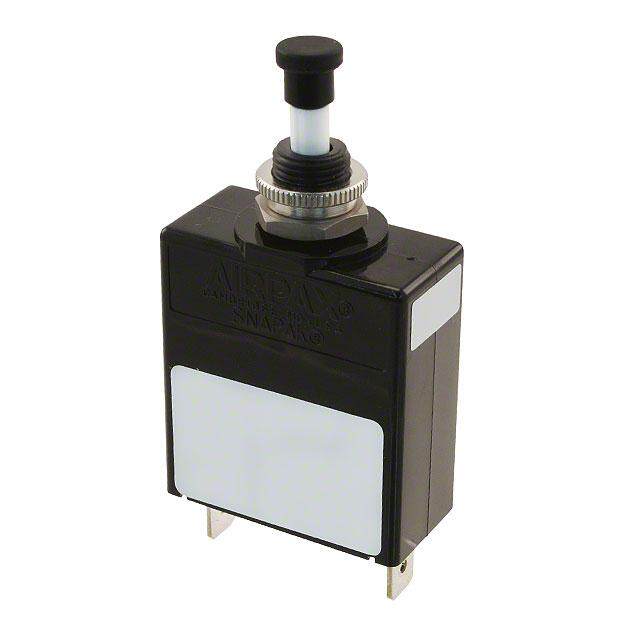
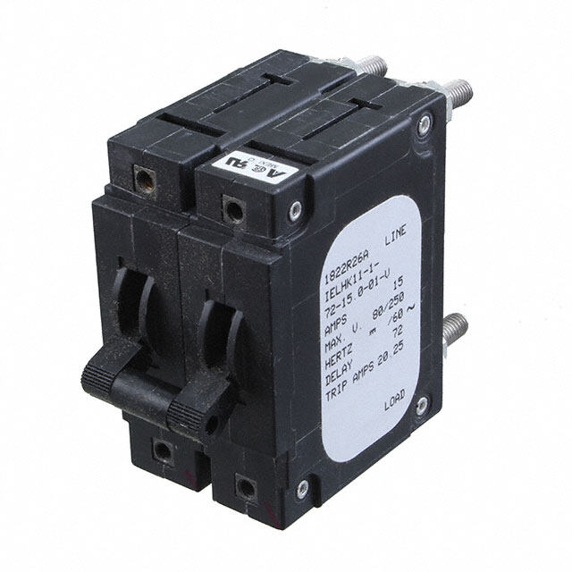
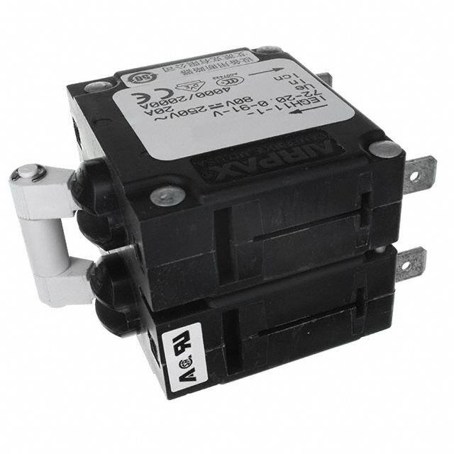
- 型号: IEGH11-1-72-20.0-91-V
- 制造商: Sensata Technologies/Airpax
- 库位|库存: xxxx|xxxx
- 要求:
| 数量阶梯 | 香港交货 | 国内含税 |
| +xxxx | $xxxx | ¥xxxx |
查看当月历史价格
查看今年历史价格
IEGH11-1-72-20.0-91-V产品简介:
ICGOO电子元器件商城为您提供IEGH11-1-72-20.0-91-V由Sensata Technologies/Airpax设计生产,在icgoo商城现货销售,并且可以通过原厂、代理商等渠道进行代购。 IEGH11-1-72-20.0-91-V价格参考¥185.30-¥598.00。Sensata Technologies/AirpaxIEGH11-1-72-20.0-91-V封装/规格:断路器, 。您可以下载IEGH11-1-72-20.0-91-V参考资料、Datasheet数据手册功能说明书,资料中有IEGH11-1-72-20.0-91-V 详细功能的应用电路图电压和使用方法及教程。
| 参数 | 数值 |
| 产品目录 | |
| 描述 | CIR BRKR 20A 250VAC 80VDC |
| 产品分类 | |
| 品牌 | Sensata Technologies/Airpax |
| 数据手册 | |
| 产品图片 | |
| 产品型号 | IEGH11-1-72-20.0-91-V |
| rohs | 无铅 / 符合限制有害物质指令(RoHS)规范要求 |
| 产品系列 | IEG |
| 产品目录绘图 |
|
| 产品目录页面 | |
| 其它名称 | 723-1163 |
| 安装类型 | 面板安装 |
| 断路器类型 | 磁性(液力延迟) |
| 极数 | 2 |
| 标准包装 | 20 |
| 照明 | - |
| 照明电压(标称值) | - |
| 特色产品 | http://www.digikey.com/cn/zh/ph/Sensata/magnetic_circuit_protectors.html |
| 相关产品 | /product-detail/zh/C1113%2F42/335-1029-ND/1995320 |
| 致动器类型 | 按片 |
| 额定电压-AC | 250V |
| 额定电压-DC | 80V |
| 额定电流 | 20A |


- 商务部:美国ITC正式对集成电路等产品启动337调查
- 曝三星4nm工艺存在良率问题 高通将骁龙8 Gen1或转产台积电
- 太阳诱电将投资9.5亿元在常州建新厂生产MLCC 预计2023年完工
- 英特尔发布欧洲新工厂建设计划 深化IDM 2.0 战略
- 台积电先进制程称霸业界 有大客户加持明年业绩稳了
- 达到5530亿美元!SIA预计今年全球半导体销售额将创下新高
- 英特尔拟将自动驾驶子公司Mobileye上市 估值或超500亿美元
- 三星加码芯片和SET,合并消费电子和移动部门,撤换高东真等 CEO
- 三星电子宣布重大人事变动 还合并消费电子和移动部门
- 海关总署:前11个月进口集成电路产品价值2.52万亿元 增长14.8%
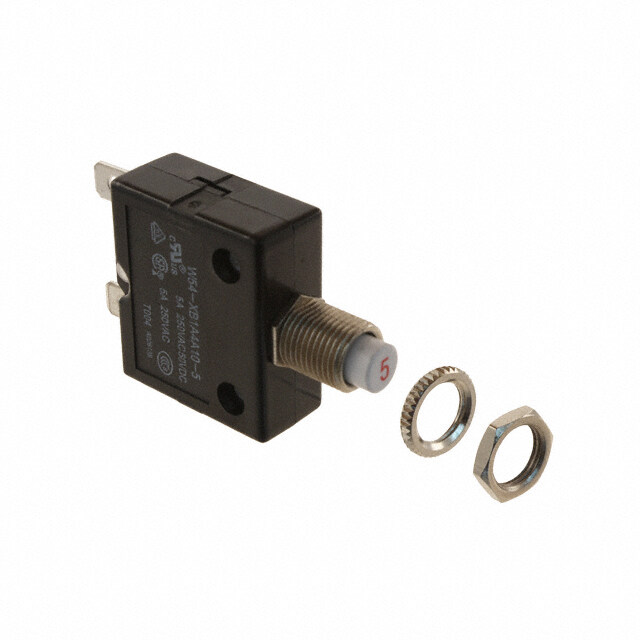

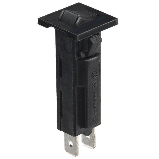
PDF Datasheet 数据手册内容提取
IAG/IUG/IEG/CEG/LEG Series Magnetic Circuit Protectors Introduction • 99 Poles • 100 Handles • 103 Configurations • 108 Operating Characteristics • 110 Delay Curves • 111 Specifications • 115 Decision Tables • 117
IAG/IUG/IEG/CEG/LEG Series Hydraulic Magnetic Circuit Protectors INTRODUCTION The Airpax™ IAG/IUG/IEG/CEG/LEG magnetic circuit protectors equipment, vending and amusement machines, military provide low-cost power switching, reliable circuit protection applications and wherever precision operation is required. and accurate circuit control for equipment in the international Temperature differences which affect fuses and other thermal marketplace. devices are not a concern. IEG models meet IEC spacing requirements which is mandatory One important feature of this protector line is a “trip free” action, for equipment that must comply with IEC specifications 601 and which means the circuit will trip in the presence of an overload 950 and VDE specifications 0804 and 0805. In addition, they are even though the handle is held in the ON position. The delay UL Recognized as supplementary protectors per UL STD. 1077, mechanism senses the fault and the contacts open. CSA Certified as supplementary protectors per CSA C22.2–No. 235, VDE Approved to VDE 0642 (EN60934), CCC Approved and CE The IAG/IUG/IEG/CEG/LEG is available in a wide variety of Compliant. IAG models are for those applications where the unit’s configurations including series, series with auxiliary switch, inherent attributes are desired, but compliance with the various shunt and relay with a choice of delays and ratings in either standards is not required. DC, 50/60Hz or 400Hz versions. Handles come in seven different colors and international markings are standard. Single or multi- Designed using the latest in sensitive hydraulic magnetic pole versions are available, with a variety of pole arrangements technology, the IAG/IUG/IEG/CEG/LEG line adapts itself to many to meet your specifications. Four pole models require a double applications and environments. They’re ideal for data processing toggle handle. Units with a handle per pole come in one through and business machines, medical instrumentation, broadcast six pole assemblies. 99 IAG Series - Introduction http://airpax.sensata.com
s e ri e S G A I SINGLE POLE CIRCUIT PROTECTOR Single Pole Mounting Detail +.010 -.000 .625 .590 [15.00] 2.1X4 06 –[3 3.526 T] H DREEEAPD +-..2050 MAX. 15.88 M3 ISO THD. OPTIONAL 2.000 ON OFF .1.660 [14.26.6106] 1.050 [50.80] [42.16] [26.67] 1.220 [31.00] 2X 0.156 [3.96] .750 .168 [19.05] [4.27] .230 [5.84] 1.530 [38.86] Note: Tolerance ±.015 [.38] unless noted. Dimensions in brackets [ ] are millimeters. LEG Type Units Require Screw Terminals IAG Series - Poles 100
MULTI-POLE CIRCUIT PROTECTORS (IAG/IUG/IEG/CEG/LEG) Two Pole Protectors all units simultaneously. A single toggle handle operates all three poles for quick and convenient control, or if preferred, a handle An assembly consisting of two single pole units, having their trip per pole is available. The four pole construction consists of four mechanisms internally coupled and with a single toggle handle, single pole units assembled with an internal mechanical forms the IEG11 with quick-connect D.I.N.-style terminals. interlock which actuates all units simultaneously. A double Individual poles may differ in ratings, delays and internal toggle handle operates all four poles. The individual poles need connections. An auxiliary switch may be included in either or not have identical characteristics and any series trip pole may both poles, allowing you to mix SELV and hazardous voltages. have an auxiliary switch. If screw-type terminals are required, Rugged screw-type terminals can be provided, in which case the the breaker designation will be IEG666 for a three pole version designation would be IEG66. The IEGH offers a toggle handle for and IEG6666 for a four pole version. each pole. LEG type units are avavailable only in one or two pole configurations. Protector poles are numbered consecutively when viewed from Three Pole and Four Pole Protectors the terminal side, with the ON position up, starting with Pole #1 on the left side and proceeding to the right. The three pole construction consists of three single pole units assembled with an internal mechanical interlock which actuates IAG/IUG/IEG/CEG/LEG Multi-Pole Circuit Breakers IAG/IUG/IEG/CEG/LEG 1.687 .240 Two Pole* Three Pole* Four Pole* [42.85] [6.10] ON 32º ON OFF ON OFF ON OFF ON OFF 32º OFF 2.075 .690 1.515 2.265 3.015 [52.71] [17.53] [38.48] [57.53] [76.58] MAX. MAX. MAX. MAX. (Optional: Handle may be located in Pole 1 instead of Pole 2) LEG Type Units Require Screw Terminals .230 Two Pole* Three Pole* Four Pole* [5.84] 2X .625+-..001000 [15.88+.25 [ -.00 1.530 [38.86] 1.660 [42.17] 1.050 [26.68] 4X .156 .750 .750 .750 .750 .750 .750 [3.96] [19.05] [19.05] [19.05] [19.05] [19.05] [19.05] Panel Mounting Detail: Tolerance for Mtg. ±.005 [.13] unless noted. Note: Tolerance ± .015 [.38] unless noted. Dimensions in brackets [ ] are millimeters. *See Single Pole Mounting Detail for hole sizes and locations. LEG type units are only available in one or two poles. 101 IAG Series - Poles http://airpax.sensata.com
s e ri e S G MULTI-POLE CIRCUIT PROTECTORS A I (IAGH/IUGH/IEGH/CEGH/LEGH) The IAGH/IUGH/IEGH/CEGH/LEGH two, three and four pole models are available with a handle per pole. LEGH type units are available only in two pole models. 4X 6 – 32 THREAD 2X .590 .140 [3.56] DEEP [15.00] M3 ISO THD. OPTIONAL MAX. IAGH/IUGH/IEGH/CEGH/LEGH Protectors 4X 6 – 32 THREAD 2X .590 .140 [3.56] DEEP 1.687 .240 [15.00] M3 ISO THD. OPTIONAL [42.85] [6.10] MAX. ON 2.000 1.660 ON OFF ON OFF ON OFF ON OFF ON OFF ON OFF ON OFF ON OFF ON OFF [50.80] [42.16] 32º 1.220 2.000 [31.00] 1.660 ON OFF ON OFF ON OFF ON OFF ON OFF ON OFF ON OFF ON OFF ON OFF 32º [50.80] [42.16] OFF 1.22.1068 1.515 2.265 3.015 [31.[040.2]7] [38.48] [57.53] [76.58] MAX. MAX. MAX. 2.075 .690 .168 1.515 2.265 3.015 [52.70] [17.53] [4.27] [38.48] [57.53] [76.58] MAX. MAX. MAX. MAX. LEG (Requires Screw Terminals) Two Pole Three Pole* Four Pole* .230 +.010 [5.84] -.000 2X .625 +.25 -.00 1+.50.1807 -.000 2X .625 1.660 [13.85.3806] 15+-...820570[4 2.16] 1.050 [26.67] 1.660 [4 2 4 . 1X 6 ] [ 3 .[.11295.6606.]5607] [1.795.005] [1.795.005] [1.795.005] [1.795.005] [1.795.005] [1.795.005] .750 .750 .750 4X .156 .750 .7*5S0ee Tw.7o5 P0ole Mounting Deta[i1l f9o.0r 5h]ole[ 1s9iz.e0s5 ]an[d1 9lo.0c5a]tions. [3.96] [19.05] [19.05] [19.05] Panel Mounting Detail: Tolerance for Mtg. ±.005 [.13] unless noted. LEG/LEGH Barriers (required) In order to meet UL listing requirements, the LEG/LEGH two NOTE: We recommend machining slots into your panel for 2 or more poles. This eliminates the need to dissemble/reassemble the handle pole model requires barriers. Available with a standard ties to be able to insert the handles thru indvidiually drilled holes. LEG straight barrier or an optional “Z” type barrier. type units are only available in one or two poles. Standard Barrier Optional “Z” Barrier Note: Tolerance ± .015 [.38] unless noted. Dimensions in brackets [ ] are millimeters. Note: Tolerance ± .015 [.38] unless noted. Dimensions in brackets [ ] are millimeters. IAG Series - Poles 102 2-FRONT 2-FRONT
ROCKER CIRCUIT PROTECTORS (IAGX/IAGZX/IUGX/IUGZX/IEGX/IEGZX/CEGX/CEGZX/LEGZX) The IAGX/IUGX/IEGX/CEGX and IAGZX/IUGZX/IEGZX/CEGZX/ The IAGZX/IUGZX/IEGZX/CEGZX/LEGZX style adds our “EZ” LEGZX styles offer two attractive rocker actuator versions of our options of contrasting dual color rocker actuators, affording a popular IAG/IUG/IEG/CEG/LEG family. Designed with the operator clear visual indication of the handle position and integrated in mind, each features handles with a concave surface and handle guards, to help prevent accidental turn-on and turn-off of aesthetic appearance for front panel applications. the unit. Available with a black rocker and white, red or green indicator color for either ON or OFF indication. Both are available with rocker handle styles in a choice of five single colors: black, red, grey, orange or white. IAGX/IUGX/IEGX/CEGX S ingle Pole Two Pole Three Pole Four Pole 6 – 32 THD. (TYP.) M3 ISO THD. OPTIONAL 1.515 2.265 3.015 1.687 .750 [38.48] [57.53] [76.58] [42.85] [19.05] MAX. MAX. MAX. (Optional: Handle may be 2.206 located in Pole 2 instead 1[3.202.909] [56.03] of Pole 1) 2.000 [50.80] 1.972 ON 1.660 ON ON ON ON [50.09] [42.16] OFF OFF OFF OFF OFF 2.470 .490 ±.005 [62.74] [12.45] .735 MAX. MAX. [±.13] [18.67] Mounting Detail (HANDLE WIDTH) Single, Two & Three Pole Four Pole* 2X .156 1.510 [3.96] [38.35] Panel Mounting Detail: Tolerance for 1.660 mounting ±.005 [.13] unless noted. [42.16] *See Single Pole Mounting Detail for 1.260 .200 [32.00] hole sizes and locations. [5.08] .750 .750 [19.05] [19.05] IAGZX/IUGZX/IEGZX/CEGZX/LEGZX Single Pole* Two Pole* Three Pole Single, Two & Three Pole 2[6.427.704 M]AX. .[41200.6 R7]EF. [19.7.0550] 6 – 32 THD. (TYP.) [318.5.4185] 2[5.276.553 M] ax. 2 X [ 3 ..9165]6 1.687 .125 M3 ISO THD. [42.85] [3.18] OPTIONAL 1.660 [42.16] 1.220 1.260 2.000 [30.99] .200 [32.00] [50.80] [5.08] 1[3.583.806] 2[5.146.958] ON 1[4.626.106] ON ON ON OH(SAPENTEIDO DLNEEAT GLAUILA “RAD”)S OFF OFF OFF OF .[71590.05] 1.239 Panel Mounting Detail: Tolerance for [10.4.9320] [31.47] Mtg. ±.005 [.13] unless noted. Note: Tolerance ± .015 [.38] unless noted. Dimensions in brackets [ ] are millimeters. * LEG type units are only available in one or two poles. Detail “A” 103 IAG Series - Handles http://airpax.sensata.com
s e ri e S ROCKER CIRCUIT PROTECTORS G A (IAGBX/IUGBX/IEGBX/CEGBX/LEGBX) I The innovative new design of our IEG BX style circuit breaker Available on a variety of versions with a full range of agency features a flat front rocker that not only satisfies your aesthetic approvals, the new IEG BX style circuit breakers meet or exceed needs, it guards against accidental actuation while providing the all current performance specifications, including interrupting highest degree of circuit protection and quality. Only Sensata capacities up to 50,000 amperes. Various guard options offer Technologies offers this new standard in user interface, additional and increasing levels of actuation protection providing additional peace of mind that guards alone can’t performance. The two shot mold on the flat rocker surface supply. provides a clean, crisp legend that can withstand demanding use. IAGBX/IUGBX/IEGBX/CEGBX/LEGBX Handle position Handle "OFF" with guard ON position "ON" OIN (6th decision, G) I with guard (6th decision, G) O O OFF OFF Actuation access handle 2.378 MAX .387 REF. (see note) [60.40] [9.84] .125 1.687 [3.18] [42.85] 2.000 [50.80] 1.220 [30.99] 1.530 [38.86] Handle position ON Handle position ON "OFF" guard with I "ON" guard with I no actuate “OFF” no actuate “OFF” feature feature 1.239 PUTOSH (6th decision, X) PUTOSH (6th decision, X) .314 [31.47] RESET RESET [7.98] SINGLE POLE 2X ø .156 .750 [3.96] [19.05] 1.660 1.260 [42.16] [32.00] Handle position Handle position ON ON I ON "OFF" without I "ON" without 2.217 1.660 I guard guard [56.31] [42.16] OOFF .200 .750 OFOF OOFF [5.08] [19.05] OPTIONAL Panel Mounting Detail GUARD DETAIL "A" (SEE DETAIL “A”) MOUNTING DETAIL TOLERANCE: Note: Access is limited to a device smaller than the Underwriters Laborator “articulated probe” 6-32 THD. MOUNTING ±.005 [.13] UNLESS NOTED Defined in UL-489 FIG. 11.1.7.2.1. M3 ISO THD. OPTIONAL IAG Series - Handles 104
SEALED TOGGLE CIRCUIT PROTECTORS (IAGN/IUGN) The IAGN/IUGN family is a sealed toggle version of the IAG/IUG family. The silicone rubber seal around the handle assures panel seal integrity and makes this style a natural for harsh environments. This sealed toggle family is available in one to three poles with ratings of .050 to 50 amperes. Single Pole Two Pole Three Pole KEYWAY .060 [1.52] – .065 [1.65] WIDE .030 [.76] – .035 [.89] DEEP 1.515 2.265 .750 [38.48] [57.53] [19.05] MAX. MAX. .130 6 – 32 MTG. SCREW [3.30] FOR HIGH SHOCK MTG. LOCKWASHER ±3º 1.220 13º [30.99] ON 2.000 [50.80] .656 OFF ±3º [16.66] 13º 1/2 – 32 HEX NUT 2.256 (Optional: Handle may be [57.30] RUBBER “O” RING located in Pole 2 instead MAX. .625 .750 of Pole 1) [15.88] [19.05] Mounting Detail Optional Handle Single Pole Two Pole* Three Pole* .156 .750 .750 .750 [3.96] [19.05] [19.05] [19.05] .515 [13.08] .656 [16.66] Panel Mounting Detail: Tolerance for Mtg. ±.005 [.13] unless noted. *See Single Pole Mounting Detail for hole sizes and locations. Note: Tolerance ± .015 [.38] unless noted. Dimensions in brackets [ ] are millimeters. 105 IAG Series - Handles http://airpax.sensata.com
s e ri e S G A I SNAP-IN CIRCUIT PROTECTORS (IEGS/IEGHS/CEGS/CEGHS/LEGS/LEGHS) The Snap-In version of the IEG brings mounting simplification The IEGS is offered in either flush or beveled versions, in 1, 2, 3 and international spacing together in a package that is or 4 pole packages, and with a handle per pole or per unit. aesthetically enhanced. The IEGS securely snaps into a rectangular cut-out, eliminating the need for panel mounting The IEGS is UL Recognized, CSA Certified and VDE approved. hardware and the associated costs. The face plate of the IEGS is a clean, black matte and it satisfies the increasing demand for front panel components that are designed with ergonomic considerations. IEGHS/CEGHS/LEGHS Circuit Protectors (Note B) (Multi-Pole-IEGH Handles Per Pole) (Omit H for Single Pole) 1.687 .240 .744 1.488 2.232 2.976 [42.85] [6.09] [18.90] [37.80] [56.69] [75.59] ON ON ON ON ON ON ON ON ON ON ON 32º 2.000 [50.80] 32º 2.598 1.220 [65.99] [30.99] OFF OFF OFF OFF OFF OFF OFF OFF OFF OFF OFF 2.075 .690 [52.70] [17.53] MAX. DIM. “B” (SEE TABLE) Note: Panel Cutout Detail A: Flush face plate is optional. See decision tables, sixth decision. Panel Thickness: (See Table) B: Tolerance ± .031 [.79] Angles: ±5° unless noted. Dimensions in brackets [ ] are millimeters. DIM. “C” (SEE TABLE) DIM. “A” (SEE TABLE) .127 [3.23] DIMENSIONS “A”, “B”, “C” Number of Poles Dimension “A”, inches [ mm ] Dimension “B”, inches [ mm ] Dimension “C”, inches [ mm ] 1 pole .750 [19.05] max .755 [19.18] min 2 pole 1.515 [38.48] max 1.520 [38.61] min 2.180 ± .005 2.186 ± .011 3 pole 2.265 [57.53] max 2.270 [57.66] min [55.37 ± .13] [55.52 ± .28] 4 pole 3.015 [76.58] max 3.020 [76.71] min .040 to .059 .060 to .100 Panel Thickness [1.02 to 1.50] [1.52 to 2.54] IAG Series - Handles 106
IEGS/CEGS/LEGS Circuit Protectors (Note B) (Add H for multiple handles per unit, IEGHS) 1.687 .240 [42.85] [6.09] .960 1.700 2.450 3.190 [24.38] [43.18] [62.23] [81.03] ON ON ON ON ON ON 32º 2.000 [50.80] 2.598 32º 1.220 [65.99] [30.99] OFF OFF OFF OFF OFF OFF 2.075 .690 [52.70] [17.53] MAX. Panel Cutout Detail DIM. “B” Panel Thickness: (See Table) (SEE TABLE) DIM. “C” (SEE TABLE) DIM. “A” (SEE TABLE) .130 [3.30] DIMENSIONS “A”, “B”, “C” Number of Poles Dimension “A”, inches [ mm ] Dimension “B”, inches [ mm ] Dimension “C”, inches [ mm ] 1 pole .750 [19.05] max .780 ± .015 [19.81 ± .381] 2 pole 1.515 [38.48] max 1.540 ± .015 [39.12 ± .381] 2.180 ± .005 2.186 ± .011 3 pole 2.265 [57.53] max 2.290 ± .015 [58.17 ± .381] [55.37 ± .13] [55.52 ± .28] 4 pole 3.015 [76.58] max 3.040 ± .015 [77.22 ± .381] .040 to .059 .060 to .100 Panel Thickness [1.02 to 1.50] [1.52 to 2.54] Optional Handle Guard .780 [19.82] 1.560 [39.62] .734 [18.64] Note: A: Tolerance ± .015 [.38] unless noted. Dimensions in brackets [ ] are millimeters. B: Bevelled face plate is standard. 107 IAG Series - Handles http://airpax.sensata.com
s e ri e S G A I CONFIGURATIONS .230 .230 [5.84] [5.84] Series Trip The most popular configuration for magnetic protectors is the series trip where the sensing coil and contacts are in 1.530 1.530 series with the load being protected. The handle position [38.86] Series [38.86] SOwnliytch conveniently indicates circuit status. In addition to providing conventional overcurrent protection, it’s simultaneously used as an on-off switch. Shunt Trip The shunt trip is designed for controlling two separate loads with one assembly. The control is established by providing Optional flat overload protection for the critical load. When the current screw terminal 2.52 MAX. .230 [64.00] through this load becomes excessive and reaches the trip [5.84] (See Note A) point, the protector will open and remove power from both loads simultaneously. The total current rating of both loads 1.380 [35.05] must not exceed the maximum contact rating. 1.530 Shunt Auxiliary Switch (Applies to Series Trip Only) [38.86] This is furnished as an integral part of a series pole in single or multi-pole assemblies. Isolated electrically from the protector’s circuit, the switch works in unison with the power contacts and provides indication at a remote location of the protector’s on-off status. Auxiliary switch contacts actuate simultaneously with the Standard Auxiliary Switch VDE Auxiliary Switch main protector contacts, and will open regardless of whether the protector contacts are opened manually or .441 .469 [11.20] [11.91] electrically. For auxiliary switch ratings below 6Vac or 5Vdc, an auxiliary switch with gold contacts designated as REG is available. Gold contacts are not recommended 1[2.078.531] .[82418.53] 1[2.065.990].[71694.04] for load current above 100 milliamps. 2.438 MAX. 2.454 MAX. MAIN TERMINAL TYPES .[121.709] [(6S1e.e9 3N]ote A) .[148.775] [(6S2e.e3 3N]ote A) Amp 8-32 M4 10-32 M5 Push-On .260 .250 Rating Screw Screw Screw Screw [6.60] [6.35] –IREC4 .05 to 30 X X X –IREG4 –IREC5 30.1 to 50 X X Series with Auxiliary Switch C Note: A: Terminal protrusion dimensions are referenced from back mounting panel. NO B: Main terminals are male push-on type .250 [6.35] wide x 0.31 [.79] thick x .375 [9.53] NC long or 8-32 x .187 [4.75] screw type. Metric screw terminals are M4 x 5mm (<=30A): OBFRF EPAOKSEITRI OINN M5 x 5mm screw type (>30A). On VDE approved builds with screw terminals, external tooth lockwashers are supplied. On VDE approved builds with push-on terminals a soldered connection is required above 25 amperes. IAG Series - Configurations 108
Relay Trip .230 2.52 MAX. This permits the overload sensing coil to be placed in a [5.84] [64.00] (See Note A) circuit which is electrically isolated from the trip contacts. The coil may be actuated by sensors .620 monitoring pressure, flow, temperature, speed, etc. [15.75] Other typical applications include crowbar, interlock 1.380 [35.05] and emergency /rapid shutdown circuitry. Trip may be 1.530 [38.86] accomplished by voltage or current, which must be Relay removed after trip. .230 2.52 MAX. [5.84] [64.00] (See Note A) 1.380 [35.05] Dual Coil 1.530 By combining two electrically independent coils on a [38.86] Dual Coil common magnetic circuit, it is possible to provide contact opening when either an over-current or trip voltage is applied to the respective coils. One coil will be a current trip coil with standard specifications. The second, or dual coil, can be used to provide a control function permitting contact opening from a remote interlock or other transducer functions. Standard coils .230 2.52 MAX. are 6, 12, 24, 48, 120 and 240 volts. Tripping is [5.84] [64.00] (See Note A) instantaneous and must be removed (usually self- interrupting) after trip. .620 [15.75] 1.380 [35.05] 1.530 [38.86] Dual Coil Voltage Trip Optional Barriers (IEG Only) Sometimes called “dump circuits” or “panic trip circuits,” these units make it possible to open main power contacts with lower power inputs from one or .571 [14.50] more sources. This configuration is becoming increasingly more important for sensitive circuitry and denser packaging in automation systems. Available in series, shunt or relay configurations. 2.000 [50.80] Note: Tolerance ± .015 [.38] unless noted. Dimensions in brackets [ ] are millimeters. 109 IAG Series - Configurations http://airpax.sensata.com
s e ri e S G A OPERATING CHARACTERISTICS I TYPICAL RESISTANCE / IMPEDANCE Inrush Pulse Tolerance Impedance The following table provides a comparison of inrush Current Ratings DC AC, 50/60Hz AC, 400Hz pulse tolerance with and without the inertial delay (Amps) (ohms) (ohms) (ohms) feature for each of the 50/60Hz delays. Pulse 51, 52, 53, 59 61, 62, 63, 69 41, 42, 43, 49 tolerance is defined as a single pulse of half sine wave peak current amplitude of 8 milliseconds 0.200 45.8 28.5 71.94 duration that will not trip the circuit breaker. The 1.00 1.38 1.10 2.85 table at left provides a guide to determine if the 2.00 0.371 0.29 0.76 inertia delay feature is required. Consult factory for further assistance. 5.00 0.055 0.051 0.12 10.0 0.017 0.016 0.032 20.0 0.006 0.006 0.010 INRUSH PULSE TOLERANCE 30.0 0.003 0.004 0.006 Delay Pulse Tolerance 50.0 0.0019 0.0018 — 61, 62, 63, 71, 72, 73 10 times rated current (approx) DCR and Impedance based on 100% rated current applied and stabilized for a minimum of one hour. Tolerance .05-2.5 amperes ± 20%: 2.6 -20 amperes 61F, 62F, 63F, 71F, 72F, 73F 12 times rated current (approx) ± 25%, 21-50 amperes ± 50%. Consult factory for special values and for coil impedance of delays not shown. 64, 65, 66 25 times rated current (approx) PERCENTAGE OF RATED CURRENT VS TRIP TIME IN SECONDS Delay 100% 125% 150% 200% 400% 600% 800% 1000% 41 No Trip May Trip .500 to 8.0 .150 to 1.9 .020 to .40 .006 to .25 .004 to .1 .004 to .05 42 No Trip May Trip 5 to 70 2.2 to 25 .40 to 5.0 .012 to 2 .006 to .2 .006 to .15 43 No Trip May Trip 35 to 350 12 to 120 1.5 to 20 .012 to 2.2 .01 to .22 .01 to .1 49 No Trip May Trip .100 Max .050 Max .020 Max .020 Max .020 Max .020 Max 51* No Trip .500 to 6.5 .300 to 3.0 .100 to 1.2 .031 to .500 .011 to .25 .004 to .1 .004 to .08 52* No Trip 2 to 60 1.8 to 30 1 to 10 .15 to 2.0 .015 to 1 .008 to .5 .006 to .1 53* No Trip 80 to 700 40 to 400 15 to 150 2 to 20 .015 to 9 .015 to .55 .012 to .2 59* No Trip .120 Max .100 Max .050 Max .022 Max .017 Max .017 Max .017 Max 61* No Trip .700 to 12 .35 to 7.0 .130 to 3.0 .030 to 1 .015 to .3 .01 to .15 .008 to .1 62* No Trip 10 to 120 6 to 60 2 to 20 .2 to 3.0 .015 to 2 .015 to .8 .01 to .25 63* No Trip 50 to 700 30 to 400 10 to 150 1.5 to 20 .015 to 10 .013 to .85 .013 to .5 64 No Trip .7 to 12 .35 to 7 .13 to 3 .030 to 1 .017 to .3 .01 to .16 .008 to .1 65 No Trip 10 to 120 6 to 60 2 to 20 .2 to 3 .02 to 2 .017 to .76 .01 to. 6 66 No Trip 50 to 700 30 to 400 10 to 150 1.5 to 20 .4 to 10 .014 to 5 .014 to 3 69* No Trip .120 Max .100 Max .050 Max .022 Max .017 Max .017 Max .017 Max 71** No Trip .440 to 10 .300 to 7 .100 to 3.0 .03 to 1 .012 to .3 .004 to .15 .004 to .1 72** No Trip 1.8 to 100 1.7 to 60 1 to 20 .15 to 3 .015 to 2 .008 to .79 .006 to .28 73** No Trip 50 to 600 30 to 400 10 to 150 1.8 to 20 .015 to 10 .015 to .88 .011 to .50 79** No Trip .120 Max .100 Max .050 Max .023 Max .016 Max .015 Max .015 Max *CEG type units are available only with 51, 52, ,53 and 59 delays LEG type units are available only with 61, 62, 63 and 69 delays **135% minimum trip point for delays 71, 72, 73 and 79 IAG Series - Operating Characteristics 110
DELAY CURVES (IAG/IUG/IEG/CEG/LEG) 400Hz, DC, 50/60Hz Delay Curves (typ) A choice of delays is offered for DC, 50/60Hz and 400Hz applications. Delays 49, 59 and 69 provide fast acting, instantaneous trip and are often used to protect sensitive electronic equipment (not recommended where known inrush exists). Delays 41, 51 and 61 have a short delay for general purpose applications. Delays 42, 52 and 62 are long enough to start certain types of motors and most transformer and capacitor loads. Delays 43, 53 and 63 are long delays for special motor applications at 400Hz, DC and 60Hz. CEG type units are only available in 51, 52, 53 and 59 delay curves. LEG type units are only available in 61, 62, 63 and 69 delay curves. 10000 10000 1010000 MAY TRIP DELAY 61 1010000 MAY TRIP DELAY 62 S S D D N10 N10 O O C C E E S S N 1 N 1 E I E I M M TI TI .1 .1 .01 .01 .001 .001 0 100 150 200 300 400 500 600 700 800 900 1000 0 100 150 200 300 400 500 600 700 800 900 1000 125 125 PERCENT OF RATED CURRENT PERCENT OF RATED CURRENT 101000000 MAY TRIP DELAY 63 101000000 DELAY 69 100 100 ME IN SECONDS101 ME IN SECONDS101 MAY TRIP TI TI .1 .1 .01 .01 .0010 100 150 200 300 400 500 600 700 800 900 1000 .0010 100 150 200 300 400 500 600 700 800 900 1000 125 125 PERCENT OF RATED CURRENT PERCENT OF RATED CURRENT 111 IAG Series - Delay Curves http://airpax.sensata.com
s e ri e S G A I DELAY CURVES (IAG/IUG/IEG/CEG) DC Delay Curves (typ) IAG Series - Delay Curves 112
DELAY CURVES (IAG/IUG/IEG) Multi-frequency - DC, 50/60Hz Delay Curves (typ) 10000 10000 S1100000 MAY TRIP DELAY 71 S1100000 MAY TRIP DELAY 72 D D N N O O EC EC 10 S S N N E I E I M M TI TI 1 01 01 001 001 0 100 150200 300 400 500 600 700 800 900 1000 0 100 150200 300 400 500 600 700 800 900 1000 135 PERCENT OF RATED CURRENT 135 PERCENT OF RATED CURRENT 10000 10000 1000 MAY TRIP DELAY 73 1000 DELAY 79 S100 S100 D D N N O O E IN SEC 110 E IN SEC 110 MAY TRIP M M TI TI 1 1 01 01 001 001 0 100 150200 300 400 500 600 700 800 900 1000 0 100 150200 300 400 500 600 700 800 900 1000 135 PERCENT OF RATED CURRENT 135 113 IAG Series - Delay Curves http://airpax.sensata.com
s e ri e S G A I DELAY CURVES (IAG/IUG/IEG) 400Hz Delay Curves (typ) 10000 10000 1000 DELAY 41 1000 MAY TRIP DELAY 43 NDS10100 MAY TRIP NDS10100 O O C C N SE1 N SE1 ME I ME I TI TI .1 .1 .01 .01 .001 .001 0 100 150 200 300 400 500 600 700 800 900 1000 0 100 150 200 300 400 500 600 700 800 900 1000 125 125 PERCENT OF RATED CURRENT PERCENT OF RATED CURRENT 10000 10000 1010000 MAY TRIP DELAY 42 1010000 DELAY 49 TIME IN SECONDS1.011 TIME IN SECONDS1.011 MAY TRIP .01 .01 .0010 100 150 200 300 400 500 600 700 800 900 1000 .0010 100 150 200 300 400 500 600 700 800 900 1000 125 125 PERCENT OF RATED CURRENT PERCENT OF RATED CURRENT IAG Series - Delay Curves 114
SPECIFICATIONS Trip Free Vibration Will trip open on overload, even when forcibly held in the ON position. This Circuit protector shall not trip when vibrated per MIL-STD-202, Method 204, Test prevents the operator from damaging the circuit by holding on the protector. Condition A with 100% rated current applied to delayed units and 80% rated current to instantaneous units. Trip Indication The operating handle moves positively to the OFF position on overload. VDE Approval IEG is VDE approved under VDE 0642 (EN60934). The IEG has 8mm creepage and Ambient Operation clearance between the main circuit and the following areas: IAG/IUG/IEG/CEG/LEG protectors operate in temperatures between –40° C to A. Operator accessible area around the handle. +85° C. B. The mounting inserts or brackets. C. The auxiliary switch circuit. Insulation Resistance D. Between poles. Not less than 100 megohms at 500 volts DC. Care must be taken to maintain spacings at the terminals when wired. The VDE Dielectric Strength approval for standard terminals is not for use with bare wire. A crimp type lug is IAG/IUG/IEG/CEG/LEG protectors withstand 3750Vac, 60Hz for 60 seconds required. In addition, all VDE approved units will be in compliance with specific between all electrically isolated terminals, except auxiliary switch terminals CE Directives. These units will be marked as CE Compliant. shall withstand 600Vac, 60Hz for REG and REC types. Four terminal dual coil and relay construction (not offered in the IEG) will withstand 1500Vac. UL1500 (Marine Ignition Protected) IDG/IDGH is approved for Marine Ignition Protection Endurance Operating as a switch, the operating life exceeds 10,000 operations at a rate of UL489A Listed 6 per minute when tested as follows: 6000 OPS @ rated current plus 4000 OPS The CEG is dimensionally the same as the popular IEG, but provides UL listing to @ at no load. UL489A. Available in one to three poles, in series, series with auxiliary switch, shunt, dual coil and voltage trip configurations. As a circuit breaker, the CEG Electrical Characteristics provides communication equipment manufacturers with a UL listed circuit .050-50 amperes; 80Vdc Max., 240Vac Max., 50/60Hz and .050-30 amperes: breaker in a very compact package that meets the stringent environmental 250Vac Max., 400Hz. Units above 30 amps are not suitable for across-the-line requirements of today’s marketplace. This makes the CEG ideal for switching, motor starting. transmission and wireless applications. Auxiliary Switch UL489 Listed When supplied shall be SPDT configuration. Non VDE approved switches have The LEG is dimensionally the same as the popular IEG, but provides UL listing to a maximum UL rating of 10.0 amperes, 250 volts, 60Hz; 3.0 amperes, 50 volts DC, UL489. Available with one or two poles, in series, series with auxiliary switch, 1 amperes, 80 volts DC (REC) type or 0.1 amperes, 125 volts, 60Hz. (REG type). shunt and three-terminal dual coil configurations. As a circuit breaker, the LEG provides equipment manufacturers with a UL listed magnetic hydaulic circuit VDE approved switches have a maximum UL rating of 10.0 amperes, 250 volts, breaker in the most compact package available on the market. 60Hz, 1 amperes, 80 volts DC (REG type); or 0.1 amperes, 125 volts, 60Hz (REG type); or 0.1 amperes, 125 volts, 60Hz (REG type). APPROXIMATE WEIGHT PER POLE (1 TO 6 POLES AVAILABLE) Ounces Grams Moisture Resistance 2.2 62.4 Meets all the requirements of MIL-PRF-55629 when tested in accordance with Method 106 of MIL-STD-202. RECOMMENDED TORQUE SPECIFICATIONS Salt Spray (Corrosion) Component Torque (in-lbs) Meets the requirements of MIL-PRF-55629 when tested in accordance with Method 101 of MIL-STD-202. 6-32 Mounting Inserts 6 to 8 M3 Mounting Screws 4 to 5 Shock 8-32 Screw Terminals 10 to 12 Circuit protectors shall not trip when tested per MIL-STD-202, Method 213, Test M4 Terminal Screws 10 to 12 Condition I with 100% rated current applied to delayed units, except 90% current in plane 4 (i.e., handle down). Instantaneous units shall have 80% rated current 10-32 Screw Terminals 14 to 15 applied in all planes. M5 Screw Terminals 14 to 15 1/2 - 32 Mounting Bushing 30 to 35 Construction Where applicable, mechanical support must be provide to the terminals when Series, shunt, relay and series with auxiliary switch available in various delays applying torque and combinations. 115 IAG Series - Specifications http://airpax.sensata.com
s e ri e S G AGENCY APPROVALS A I IAG/IUG/IEG Supplementary Protectors Rated Current (Amps) Short Circuit Rating (SC), Amps Max Voltage Frequency (Hz) Phase Minimum Poles UL/CSA TÜV UL1077 & CSA TÜV 80 DC — 1 .02 to 50 .10 to 30 U2, 7500 4000 125 50/60 1 1 .02 to 50 — U2, 3000 — 125 50/60 1 1 .02 to 30 — C1, 5000(3) — 125 50/60 1 1 .02 to 50 — U3, 1000 — 125 / 250 50/60 1 2 .02 to 50 — U1, 3000 — 125 / 250 50/60 1 1 2/1 - 30/15 — C2, 5000(1) — 240 50/60 1 & 3 1 .02 to 50 — U1, 2000 — 240 50/60 1 & 3 1 .02 to 50 — C2, 5000(1) — 250 50/60 1 1 .02 to 2 — U2, 5000 — 250 50/60 1 & 3 1 .02 to 30 .10 to 50 U1, 2000 2000 250 50/60 1 & 3 1 .02 to 30 — C2, 3500(2) — 250 (4) 50/60 1 & 3 1 .02 to 30 — C1, 3500(2) — 250 (4) 50/60 1 & 3 1 .02 to 30 — U1, 1000 — 250 (5) 50/60 1 2 .02 to 50 — U3, 1000 — 250 (5) 50/60 3 3 .02 to 50 — U3, 1000 — 277 50/60 1 1 .02 to 30 — U2, 2000 — 277 50/60 1 1 .02 to 30 — C2, 5000(2) — 250 400 1 & 3 1 .02 to 30 — U2, 1500 — 250 400 3 — .02 to 30 — U3, 200 — IDG Supplementary Protectors Max Voltage Frequency (Hz) Phase Minimum Poles UL/CSA TÜV UL1077 & CSA TÜV 48 DC — 1 .02-50 — U2, 5000 — 65 DC — 1 .02-50 — U2, 3000 — 125 50/60 1 1 .02-50 — U2, 2000 — 125/250 50/60 1 2 .02-50 — U2, 1500 — 250 50/60 1 & 3 1 .02-30 — U1, 1000 — CEG Communications Equipment Circuit Breakers Max Voltage Frequency (Hz) Phase Minimum Poles UL/CSA TÜV UL489A TÜV 80 DC — 1 .05-15 — 5000 — LEG Circuit Breakers Max Voltage Frequency (Hz) Phase Minimum Poles UL/CSA TÜV UL489 TÜV 125 50/60 1 1 .05-30 .10-30 5000 2000 120/240 50/60 1 2 1-30 .10-30 5000 2000 Notes: (1) With 125 A max. series fuse; (2) With 80 A max. series fuse; (3) With 50 A max. circuit breaker; (4) With blocked vent construction; (5) Non-standard construction. “Fit for further use” approval General notes: 0 – tested at 1.5 times amp rating for general use All supplementary protectors are of the overcurrent (OC) type 1 – tested at 6 times AC rating or 10 times DC rating for motor starting The family of protectors has been evaluated for end use application for use groups (UG) A, B, C and D The short circuit current rating (SC) – The short circuit rating in amperes following a letter and number designating the test conditions and any calibration following the short circuit test is defined below: The terminals (FW) are suitable for factory wiring only (0) C – Indicates short circuit test was conducted with series overcurrent protection The maximum voltage ratings for which the protectors have been tested are shown in the chart U – Indicates short circuit test was conducted without series overcurrent protection The current is the amperage range that the protectors have been tested 1 – Indicates a recalibration was not conducted as part of the short circuit testing The tripping current (TC) for all of the protectors is “1” (in the range of 125% to 135% of ampere rating except for the 400Hz protectors which is “2” (more than 135% of ampere rating) 2 – Indicates a recalibration was performed as part of the short circuit testing The overload rating (OL) - designates whether the protector has been tested for general use or motor 3 – Indicates recalibration was performed along with the dielectric and voltage withstand for “Suitable for starting applications. Further Use” rating IAG Series - Specifications 116
1 First Decision 5 Fifth Decision 6 Sixth Decision IAG/IUG/IEG/CEG DECISION TABLES Select Type and Terminal Rated Current Optional Type Description Handle and Mounting Options Standard ratings listed. For other ratings, Standard hardware. No designation required. The ordering code for IAG/IUG/IEG/CEG/IDG circuit IIIAUEGGG*** One toggle handle per unit Sntoa nddesairgdn taotgiognle r/emquoiurendti ng, pleas e c o.1nt0a0ct the factory. 10.0 -A Metric thread mounting inserts and terminals protectors may be determined by following the CUG+ S Toggle w/ snap-in mounting .250 15.0 -B Barriers* decision steps in the tables shown here. CIAEGGH++ X Rocker w/ standard mounting* .500 20.0 -C 277V (50/60Hz only) (See note 3) IIUEGGHH*** One toggle handle per pole ZX ZX Rocker w/ integral mounting* 1 ..07050 3305..00* -G Hvearnsdiolen sg uoanrldy), (available in ZX, BX and snap-in The coding given permits a self-assigning part CUGH+ BX BX Rocker w/ integral mounting CEGH++ 2.50 40.0* -L Handle lock number but with certain limitations. Special IDG*** Omnaeri ntoeg iggnlei thioann dplreo pteecrt uionnit, NNote: AdSde a"Fle" dfo rt oflgatg slcer eww/ tbeurmshinianlgs mounting** 5.00 50.0* -M Handle in opposite pole (2 pole only) applications may require a factory-assigned part IDGH*** One toggle handle per pole ** *N Aovt aaivlaabillaeb olen loyn o mn iIdA-Gtr,i pIU uGn iutsnits 7.50 -Q APG style “FAT” handle number. Typical examples are units with mixed marine ignition protection * IDG/IDGH is rated for 30 amps max. -S Face plate sides flush with protector (see note 4) IMG** One toggle handle per unit ratings, combinations of styles, or constructions not CMG++ mid-trip indication -X Handle guard with no actuation feature listed in the third decision table. With these, it is IMGH** One toggle handle per pole 2 Second Decision (inBdXi craotciokenr) only) (Not available with mid-trip sdAurdagdwgiteiinosgntesad lal ytnh, diat tai so p rsadtreatrn n deuanmrtdrby ep bro ewli cbilyyl btdoee esescstrtaiapbbtlilioissnhh aeand d. /or C***++U** +UMU* LUL LUGR4L RL84eH 98ceRAo9c+eoAg cL+gnLoinsiigzstientezmeeddizdd, e iC C,dCd SCSS -UAStAArA L C iC1Cp eCe5e rer0irttntir0ifiitfifidiefieeidedcdda V,t DVioDEn EA Appprporvoevded 1PTeursmhP-iononalelss and6ST Teecrrrmemwiinnaallss Single pole T7oggHSleea vnHedanlnethd C lDeoleocri sainodn Marking Selection N12 34.... o OWwVItEeDniGshlelE:eS b noa es rptt hsapmunirsoopd vripaseelr indddeo defatas.t c ucU2ers5ni epp0idttlV ia,woA ttneaiCls blh blmaees ao rbyna eetbev emde lu eaasdyte 2dbs5i eda0 essV us r((be5ssq0etu/ei6ti ur0petHged.zd9. o 0an)nldy. )U.S. thread 11 66 Two pole Marked * Not available on snap-in units factory-assigned part number whenever a ON-OFF 111 666 Three pole Color Unmarked I-O descriptive drawing exists to provide cross 1111 6666 Four pole Black -00 -01 (STD) reference, traceability and manufacturing control. *Not available in toggle seal handle type. Yellow -10 -11 When specifying a circuit protector for AC motor Example: Red -20 -21 start or high inrush applications, the peak IEG 1 - 1REC4 - 61 - 20.0 - 01 - V Blue -30 -31 amplitude and surge duration should be specified Green -40 -41 for factory assistance in rating selection. 1 2 3 4 5 6 7 Orange -60 -61 White -90 -91 For example, the following is the code for a single Handle marking color is white on black, red, blue & green pole, IEG quick-connect type terminal, series unit handles and black on white, yellow and orange handles. 3 Third Decision 4 Fourth Decision See alternate 7th decision below for X, ZX & BZ rocker handles. with auxiliary switch, designed for operation in a Internal Configuration Frequency and Delay 50/60Hz circuit. It has a short time delay, a rating of -0 Switch only SW Switch only 20 amperes, a black marked handle and is VDE -1 Series -41 400Hz short delay approved. -1REC4 Series w/ auxiliary switch * -42 400Hz long delay 7 Seventh Decision .110 quick connect -43 400Hz motor start Rocker Handle Color, Indicator Color and Marking Selection (See Notes) To determine the ordering number for your -1REC5 Series w/ auxiliary switch * -49 400Hz 150% instant trip IAGX, IUGX, IEGX, IAGZX, IUGZX, IEGZX, CUGZX, CEGZX Rocker Handle (Single Rocker Color) .187 quick connect particular IAG/IUG/IEG/CEG unit, simply follow the -51 DC short delay* Vertical Mounting Horizontal Mounting -1REG4 Series w/ auxiliary switch steps shown. You may use this number to place an (gold contacts)* -52 DC long delay* Rocker On-Off On-Off order or as a reference for further questions you .110 quick connect -53 DC motor start* HCoanlodrle ICnodliocrating MCoalrokring Indicates: Unmarked OFing-.1Off IF-iOg .2 IF-iOg.3 OFing-.4Off IF-iOg .5 IF-iOg.6 MDeatrakiilng may have. -1RS4 Seleercietrsic wal/ tarliapr,m switch, -59 DC 125% instant trip* Black N/A White N/A -00 -01 -02 -03 -04 -05 -06 .110 Q.C. terminals -61 50/60Hz short delay Red N/A White N/A -20 -21 -22 -23 -24 -25 -26 -1RLS4 Series w/ alarm switch, -62 50/60Hz long delay Grey N/A Black N/A -40 -41 -42 -43 -44 -45 -46 A electrical trip, -63 50/60Hz motor start Orange N/A Black N/A -50 -51 -52 -53 -54 -55 -56 .110 Q.C. terminals (mid-trip only) White N/A Black N/A -90 -91 -92 -93 -94 -95 -96 -64 50/60Hz short delay -3 Shunt IAGZX, IUGZX, IEGZX, CUGZX, CEGZX Rocker Handle (Dual Rocker Color) -65 50/60Hz long delay Notes: -4 Relay -66 50/60Hz motor start Black White White On -A0 -A1 -A2 -A3 -A4 -A5 -A6 Black Red White On -B0 -B1 -B2 -B3 -B4 -B5 -B6 * t hOrneley poonlee auunxitisli.a Sryw sitwchit cish liosc naoterdm ianl ltyh seu rpigphlite-dh aonnd t pwool eor -69 50/60Hz 125% instant trip Black Green White On -C0 -C1 -C2 -C3 -C4 -C5 -C6 A A. It is recommended that power leads be soldered to circuit (viewed from terminal end) unless otherwise specified. -71 DC/60Hz short delay Black White White Off -F0 -F1 -F2 -F3 -F4 -F5 -F6 protectors having push-on type terminals for current trip -72 DC/60Hz long delay Black Red White Off -G0 -G1 -G2 -G3 -G4 -G5 -G6 ratings above 20 amperes. Black Green White Off -H0 -H1 -H2 -H3 -H4 -H5 -H6 -73 DC/60Hz motor start B. When “A” (metric thread mounting) is specified in the sixth -79 DC/60 Hz 135% instant trip Black White White On -J0 -J1 -J2 -J3 -J4 -J5 -J6 Black Red White On -K0 -K1 -K2 -K3 -K4 -K5 -K6 B decision in combination with screw terminal option in the For addition of inertial delay, add an ìFî to any second decision, metric screw terminals are supplied. d* eClaEyG n tuypmeesr aalr.e only available with DC ratings Black Green White On -L0 -L1 -L2 -L3 -L4 -L5 -L6 IAGBX, IUGBX, IEGBX, CUGBX, CEGBX Rocker Handle (Dual Rocker Color) C. IEG, IEGH, IEGS, IEGHS, IEGX and IEGZX circuit protectors are Black White White Off -M0 N/A -M2 -M3 N/A -M5 -M6 C = CCC Approved V = VDE and CCC Approved Black Red Red Off -N0 N/A -N2 -N3 N/A -N5 -N6 designed to meet 8mm creepage and clearance requirements C fmoer ainssutraeldla tinio InE CCa 6t6e4g.o Irnyt eIInId, ePdo lfluotri ouns eD ieng ereqeu i3p,m Ceanste d Ae saigsn ed Tofh tish ea ppparrto nvaulm rebqeur.i r Tehse t huen iat dwdililt inoont obfe a V CD Ea tA tphper eonvded. Taapth pteh rseoh veaandld eo dop fta itorheneas s.p Tadhretins n oautpemp VbrDoevEr.a aTl nhredeq CVuC iwrCei sl(l i tfbh aeep aapddldidceaitdbio lteno) oanf ya V BBllaacckk GYerleloenw GYerleloenw OOffff --PR00 NN//AA --PR22 --PR33 NN//AA --PR55 --PR66 part number formed entirely from shaded decisions. Notes: A. Bezels of IAGBX, IUGBX, IEGBX, CUGBX, CEGBX are black. to comply with IEC 601 and 950 and VDE 0804 If non-shaded areas are selected, the unit will not be VDE or B. Consult factory for other marking options. and 0805. CCC Approved, but other approvals still apply. 117 IAG Series - Decision Tables http://airpax.sensata.com
s e ri e S G A 1 First Decision 5 Fifth Decision 6 Sixth Decision R OCCOKLEORR HANDLE INDICATING COLOR I Select Type and Terminal Rated Current Optional ON ON Type Description Handle and Mounting Options Standard ratings listed. For other ratings, Standard hardware. No designation required. OFF OFF R OCCOKLEORR HANDLE IIIAUEGGG*** One toggle handle per unit Sntoa nddesairgdn taotgiognle r/emquoiurendti ng, pleas e c o.1nt0a0ct the factory. 10.0 -A Metric thread mounting inserts and terminals I N CDOICLOATRING CCIAUEGGGH+++ SX TRoogcgkeler ww// ssntaanpd-ianr dm mouonutnintigng* ..255000 1250..00 --BC B27a7rrVie (r5s0*/60Hz only) (See note 3) LINE MOUINNDTIICNAGT/AIINO, DNBI ,C“ COANTO”R CODE: LINE MOIUNNDTICINAGTI/FOIN, NGD ,I“ COHAF TFO”R CODE: IIUEGGHH*** One toggle handle per pole ZX ZX Rocker w/ integral mounting* 1 ..07050 3305..00* -G Hvearnsdiolen sg uoanrldy), (available in ZX, BX and snap-in LLIONAED OOFNF O OOOFNF LINOFEFLOONADLINOE LOADLINOOFEFLOONAD CCIDUEGGG*HH*+*++ Omnaeri ntoeg iggnlei thioann dplreo pteecrt uionnit, NBNoXte: AdBSdeX a" FRle"o dfco krt oeflrga twg slc/e ri enwwt/e tbegurrmsahlin mianlgos umnotiunngting** 25..5000 4500..00** --LM HHaannddllee lionc okpposite pole (2 pole only) FIG. 1 FIG. M2ARFIKG.I N3G DFEIGT. A4IL “A” F(SIGE. 5E TABLFEIG). 6 IDGH*** One toggle handle per pole ** *N Aovt aaivlaabillaeb olen loyn o mn iIdA-Gtr,i pIU uGn iutsnits 7.50 -Q APG style “FAT” handle INDICATING COLOR marine ignition protection * IDG/IDGH is rated for 30 amps max. -S Face plate sides flush with protector (see note 4) OFF IMG** One toggle handle per unit LINE CIMMGGH+*+* mOnide- ttroigpg inled hicaantidolne per pole 2 Second Decision -X H(inBadXni cdraoletci okgenur)a ordn lwy)i t(hN onto a avcatiulaabtiloen w feitaht umreid -trip ON R OCCOKLEORR HANDLE CMGH++ mid-trip indication Poles and Terminals 7 Seventh Decision ***++U** +UU* LUL LUR4L RL84e 98ceRAo9ceoAg cLgnLoinsiigzstientezeeddizdd, e C C,Cd SCSS UASAAA L C C1C eCe5erer0rtttir0ifiitfifiiefieededdd V, DVDE EA Appprporvoevded 11PT1eursmh-ionnals 66STe6crrmewinals STwinog lpeo pleole ToggHlea nHdalned Cleolor and MarkingMO SNaer-lekOecFtdFion N12 34*.... o NOWwVItEoeDniGtshl elE:aeS b vnoa esa rptt ihsapmlaunirsboopd lvripaeseelr iondddeno defa tas.st c ucUn2ersa5ni eppp0idtt-lV iai,wonA ttne aiCuls blh n blmaeiets sao rbyna eetbev emde lu eaasdyte 2dbs5i eda0 essV us r((be5ssq0etu/ei6ti ur0petHged.zd9. o 0an)nldy. )U.S. thread LLIONAEDFIOGOFN.F 1 FIGO. 2 FIOOGOFN.F 3 LOOAFNDIG.O L4FINFE MLOOAFUDIIGNN.D TL5OIIINCNEAGT/IIJNOL, DONKOIA ,NFC“ DOLIGANT.O LO6O”FINFRE CODE: 111 666 Three pole Color Unmarked I-O MARKING DETAIL “B” (SEE TABLE) 1111 6666 Four pole Black -00 -01 (STD) *Not available in toggle seal handle type. Yellow -10 -11 Example: Red -20 -21 IEG 1 - 1REC4 - 61 - 20.0 - 01 - V Blue -30 -31 LINE OFOFOIN Green -40 -41 1 2 3 4 5 6 7 Orange -60 -61 INDICATION “OFF” MOUNTING/INDICATOR CODE: M, N, P, R White -90 -91 LOAD ON LINELOAD Hhaannddllees m anardk ibnlgac cko olonr wish witeh,i tyee ollno wbl aacnkd, roerda,n bgleu eh a&n dglreese.n LINE O OOFF OOFF ON 3 Third Decision 4 Fourth Decision See alternate 7th decision below for X, ZX & BZ rocker handles. MARKINFIGG. 2DETFAIGI.L 3 “C” (SFEIGE. 6 TABLE) Internal Configuration Frequency and Delay -0 Switch only SW Switch only -1 Series -41 400Hz short delay -1REC4 Series w/ auxiliary switch * -42 400Hz long delay 7 Seventh Decision .110 quick connect -43 400Hz motor start Rocker Handle Color, Indicator Color and Marking Selection (See Notes) -1REC5 Series w/ auxiliary switch * -49 400Hz 150% instant trip IAGX, IUGX, IEGX, IAGZX, IUGZX, IEGZX, CUGZX, CEGZX Rocker Handle (Single Rocker Color) .187 quick connect -51 DC short delay* Vertical Mounting Horizontal Mounting -1REG4 Series w/ auxiliary switch (gold contacts)* -52 DC long delay* Rocker On-Off On-Off .110 quick connect -53 DC motor start* HCoanlodrle ICnodliocrating MCoalrokring Indicates: Unmarked OFing-.1Off IF-iOg .2 IF-iOg.3 OFing-.4Off IF-iOg .5 IF-iOg.6 MDeatrakiilng -1RS4 Seleercietrsic wal/ tarliapr,m switch, -59 DC 125% instant trip* Black N/A White N/A -00 -01 -02 -03 -04 -05 -06 .110 Q.C. terminals -61 50/60Hz short delay Red N/A White N/A -20 -21 -22 -23 -24 -25 -26 -1RLS4 Series w/ alarm switch, -62 50/60Hz long delay Grey N/A Black N/A -40 -41 -42 -43 -44 -45 -46 A electrical trip, -63 50/60Hz motor start Orange N/A Black N/A -50 -51 -52 -53 -54 -55 -56 .110 Q.C. terminals (mid-trip only) White N/A Black N/A -90 -91 -92 -93 -94 -95 -96 -64 50/60Hz short delay -3 Shunt IAGZX, IUGZX, IEGZX, CUGZX, CEGZX Rocker Handle (Dual Rocker Color) -65 50/60Hz long delay -4 Relay Black White White On -A0 -A1 -A2 -A3 -A4 -A5 -A6 -66 50/60Hz motor start Black Red White On -B0 -B1 -B2 -B3 -B4 -B5 -B6 * t hOrneley poonlee auunxitisli.a Sryw sitwchit cish liosc naoterdm ianl ltyh seu rpigphlite-dh aonnd t pwool eor -69 50/60Hz 125% instant trip Black Green White On -C0 -C1 -C2 -C3 -C4 -C5 -C6 A (viewed from terminal end) unless otherwise specified. -71 DC/60Hz short delay Black White White Off -F0 -F1 -F2 -F3 -F4 -F5 -F6 -72 DC/60Hz long delay Black Red White Off -G0 -G1 -G2 -G3 -G4 -G5 -G6 Black Green White Off -H0 -H1 -H2 -H3 -H4 -H5 -H6 -73 DC/60Hz motor start -79 DC/60 Hz 135% instant trip Black White White On -J0 -J1 -J2 -J3 -J4 -J5 -J6 Black Red White On -K0 -K1 -K2 -K3 -K4 -K5 -K6 B For addition of inertial delay, add an ìFî to any delay numeral. Black Green White On -L0 -L1 -L2 -L3 -L4 -L5 -L6 * CEG types are only available with DC ratings IAGBX, IUGBX, IEGBX, CUGBX, CEGBX Rocker Handle (Dual Rocker Color) Black White White Off -M0 N/A -M2 -M3 N/A -M5 -M6 C = CCC Approved V = VDE and CCC Approved Black Red Red Off -N0 N/A -N2 -N3 N/A -N5 -N6 C The shaded areas denote VDE and CCC (if applicable) Black Green Green Off -P0 N/A -P2 -P3 N/A -P5 -P6 Tofh tish ea ppparrto nvaulm rebqeur.i r Tehse t huen iat dwdililt inoont obfe a V CD Ea tA tphper eonvded. aapt pthreo veanld o opft itohnes .p Tahrtis n aupmpbroevr.a Tl hreeq Vu iwreisll tbhee aaddddeitdio tno oanf ya V Black Yellow Yellow Off -R0 N/A -R2 -R3 N/A -R5 -R6 part number formed entirely from shaded decisions. Notes: A. Bezels of IAGBX, IUGBX, IEGBX, CUGBX, CEGBX are black. If non-shaded areas are selected, the unit will not be VDE or B. Consult factory for other marking options. CCC Approved, but other approvals still apply. IAG Series - Decision Tables 118
5 Fifth Decision 6 Sixth Decision 1 First Decision Rated Current Optional Select Type and Terminal Use three numbers to print required current value Standard hardware. No designation required. LEG DECISION TABLES between .100 amps minimum and 30.0 amps maximum. Type Description Handle and Mounting Options -A Metric thread mounting inserts and terminals For example, use: LEG One toggle handle per unit Standard toggle/mounting, .100 or 2.00 or 10.0 -G Handle guard, (available in ZX, BX and snap-in The ordering code for LEG circuit breakers may be LMG Omnide- ttroigpg inled hicaantidolne per unit no designation required versions only) determined by following the decision steps in the tables S Toggle w/ snap-in mounting -L Handle lock LEGH One toggle handle per pole shown here. One toggle handle per pole ZX ZX Rocker w/ integral mounting* -S Face plate sides flush with breaker LMGH mid-trip indication BX BX Rocker w/ integral mounting -X* Handle guard with no actuation feature Note: All types are UL489 listed, CUL certified Note: Add "F" for flat screw terminals (BX rocker only) The coding given permits a self-assigning part number * Not available on mid-trip units -Z "Z" Barriers but with certain limitations. Special applications may require a factory-assigned part number. Typical examples N1. oOtense: or more descriptions may be used as required. 2. When this is not used, table one may be substituted and U.S. thread are units with mixed ratings, combinations of styles, or will be supplied. Unit will be rated at 250V (50/60Hz only.) 3. LEGS standard face plate has beveled sides(see pg. 90) constructions not listed in the third decision table. With * Not available on mid-trip units these, it is suggested that order entry be by description 2 Second Decision 7 Seventh Decision and/or drawings and a part number will be established. Poles and Terminals Handle Color and Marking Selection Additionally, it is standard policy to establish a factory- PTeursmh-ionnals STecrrmewinals Toggle Handle assigned part number whenever a descriptive drawing 1 6 Single pole Marked ON-OFF exists to provide cross reference, traceability and 11 66 Two pole Color Unmarked I-O manufacturing control. *Not available in toggle seal handle type. Black -00 -01 (STD) Yellow -10 -11 When specifying a circuit breaker for AC motor start Red -20 -21 or high inrush applications, the peak amplitude and surge duration should be specified for factory assistance in Example: Blue -30 -31 rating selection. LEG 6 - 1REC4 - 61 - 20.0 - 01 - V Green -40 -41 Orange -60 -61 For example, the following is the code for a single 1 2 3 4 5 6 7 White -90 -91 pole, LEG screw type terminal, series unit with auxiliary Handle marking color is white on black, red, blue & green switch, designed for operation in a 50/60Hz circuit. It has handles and black on white, yellow and orange handles. See alternate 7th decision below for ZX & BZ rocker handles. a short time delay, a rating of 20 amperes, a black marked handle and is VDE approved. 3 Third Decision 4 Fourth Decision Internal Configuration Frequency and Delay To determine the ordering number for your particular LEG -1 Series -61 50/60Hz short delay unit, simply follow the steps shown. You may use this -1REC4 Series w/ auxiliary switch * -62 50/60Hz long delay 7 Seventh Decision .110 quick connect number to place an order or as a reference for further -63 50/60Hz motor start Rocker Handle Color, Indicator Color and Marking Selection (See Note) questions you may have. -1REC5 S.1e8r7ie qsu wic/k a cuoxnilniaercyt switch * -69 50/60Hz 125% instant trip LEGZX Rocker Handle (Single Rocker Color) For addition of inertial delay, add an “F” to any Vertical Mounting Horizontal Mounting -1REG4 Series w/ auxiliary switch* delay numeral. (Not available on units rated at (gold contacts) 1*2 C5EVGA Cty).pes are only available with DC ratings Rocker On-Off On-Off .110 quick connect Handle Indicating Marking On-Off I-O I-O On-Off I-O I-O Marking Color Color Color Indicates: Unmarked Fig.1 Fig.2 Fig.3 Fig.4 Fig.5 Fig.6 Detail -1RS4 Series w/ alarm switch*, electrical trip, Black N/A White N/A -00 -01 -02 -03 -04 -05 -06 .110 Q.C. terminals V = VDE Approved Red N/A White N/A -20 -21 -22 -23 -24 -25 -26 -1RLS 4 Series w/ alarm switch*, The shaded areas denote VDE approval Grey N/A Black N/A -40 -41 -42 -43 -44 -45 -46 A e.1l1e0c tQri.cCa.l tterripm, imnaidls- trip only, oopf tai oVn as.t tThhei se anpdp orfo tvhael rpeaqrut inreusm tbheer .a Tdhdeit iVon Orange N/A Black N/A -50 -51 -52 -53 -54 -55 -56 will be added to any part number formed White N/A Black N/A -90 -91 -92 -93 -94 -95 -96 entirely from shaded decisions. If -3 Shunt non-shaded areas are selected, the unit will LEGZX Rocker Handle (Dual Rocker Color) not be VDE Approved, but other * Only one auxiliary switch is normally supplied on two pole approvals still apply. Black White White On -A0 -A1 -A2 -A3 -A4 -A5 -A6 units. Switch is located in the right-hand pole (viewed from terminal end) unless otherwise specified. Black Red White On -B0 -B1 -B2 -B3 -B4 -B5 -B6 Notes: Black Green White On -C0 -C1 -C2 -C3 -C4 -C5 -C6 A A. W hen “A” (metric thread mounting) is specified in the sixth Black White White Off -F0 -F1 -F2 -F3 -F4 -F5 -F6 decision in combination with screw terminal option in the C = CCC Approved Black Red White Off -G0 -G1 -G2 -G3 -G4 -G5 -G6 second decision, metric screw terminals are supplied. Black Green White Off -H0 -H1 -H2 -H3 -H4 -H5 -H6 This approval requires the addition of a C at the end of the part number. The unit will not be VDE Approved. Black White White On -J0 -J1 -J2 -J3 -J4 -J5 -J6 B. L EG, LEGH, LEGS, LEGHS, LEGZX and LEGBX circuit Black Red White On -K0 -K1 -K2 -K3 -K4 -K5 -K6 B breakers are designed to meet 8mm creepage and Black Green White On -L0 -L1 -L2 -L3 -L4 -L5 -L6 clearance requirements for installation Category III, LEGBX Rocker Handle (Dual Rocker Color) Pollution Degree 3, Case A as measured in IEC 664. Black White White Off -M0 N/A -M2 -M3 N/A N/A -M6 Intended for use in equipment designed to comply with IEC Black Red Red Off -N0 N/A -N2 -N3 N/A N/A -N6 601 and 950 and VDE 0804 and 0805. C Black Green Green Off -P0 N/A -P2 -P3 N/A N/A -P6 Black Yellow Yellow Off -R0 N/A -R2 -R3 N/A N/A -R6 Notes: A. Bezels of LEGBX are black. B. Consult factory for other marking options. 119 LEG Series - Decision Tables http://airpax.sensata.com
s e ri e S 5 Fifth Decision 6 Sixth Decision R OCCOKLEORR HANDLE INDICATING COLOR G A 1 First Decision Rated Current Optional ON ON I Select Type and Terminal Use three numbers to print required current value Standard hardware. No designation required. OFF OFF R OCCOKLEORR HANDLE Type Description Handle and Mounting Options between .100 amps minimum and 30.0 amps maximum. -A Metric thread mounting inserts and terminals I N CDOICLOATRING For example, use: LLEMGG OOmnnidee- tttrooiggpgg inlleed hhicaaanntiddollnee ppeerr uunniitt Snota dnedsairgdn taotgiognle r/emqouuirnetdin g, .100 or 2.00 or 10.0 -G Hvearnsdiolen sg uoanrldy), (available in ZX, BX and snap-in LINE MOUINNDTIICNAGT/AIINO, DNBI ,C“ COANTO”R CODE: LINE MOIUNNDTICINAGTI/FOIN, NGD ,I“ COHAF TFO”R CODE: S Toggle w/ snap-in mounting -L Handle lock LEGH One toggle handle per pole LOAD ON ON LINE LOADLINE LOADLINE LOAD LMGH Omnide- ttroigpg inled hicaantidolne per pole ZBXX ZBXX RRoocckkeerr ww// iinntteeggrraall mmoouunnttiinngg* --SX* FHaacned plela gtue asridd ewsi tflhu nsho wacitthua btiroena kfeerature LINEFIGO.F 1F FIGO. 2 FIOGOF. F3 OFFIFG. 4ON OFIG. 5 OOFFFIG. 6ON Note: All types are UL489 listed, CUL certified Note: Add "F" for flat screw terminals (BX rocker only) MARKING DETAIL “A” * Not available on mid-trip units -Z "Z" Barriers Notes: INDICATING COLOR 1. One or more descriptions may be used as required. 2. When this is not used, table one may be substituted and U.S. thread OFF will be supplied. Unit will be rated at 250V (50/60Hz only.) 3. LEGS standard face plate has beveled sides(see pg. 90) LINE * Not available on mid-trip units ON R OCCOKLEORR HANDLE 2 Second Decision 7 Seventh Decision Poles and Terminals Handle Color and Marking Selection MOUINNDTIICNAGT/IIJNO, DNKI ,C“ OLANTO”R CODE: Push-on Screw Toggle Handle Terminals Terminals 1 6 Single pole Marked LINE OFF O OOFF LOADLINE LOADLINE LOADLINE ON-OFF LOADON ON ON OFF O ON OOFF 11 66 Two pole Color Unmarked I-O FIG. 1 FIG. 2 FIG. 3 FIG. 4 FIG. 5 FIG. 6 *Not available in toggle seal handle type. Black -00 -01 (STD) MARKING DETAIL “B” Yellow -10 -11 Red -20 -21 Example: Blue -30 -31 LEG 6 - 1REC4 - 61 - 20.0 - 01 - V Green -40 -41 LINE OFOFOIN Orange -60 -61 1 2 3 4 5 6 7 INDICATION “OFF” White -90 -91 MOUNTING/INDICATOR CODE: M, N, P, R Handle marking color is white on black, red, blue & green handles and black on white, yellow and orange handles. LOAD ON LINELOAD See alternate 7th decision below for ZX & BZ rocker handles. LINE O OOFF OOFF ON 3 Third Decision 4 Fourth Decision FIG. 2 FIG. 3 FIG. 6 Internal Configuration Frequency and Delay MARKING DETAIL “C” -1 Series -61 50/60Hz short delay -1REC4 Series w/ auxiliary switch * -62 50/60Hz long delay 7 Seventh Decision .110 quick connect -63 50/60Hz motor start Rocker Handle Color, Indicator Color and Marking Selection (See Note) -1REC5 S.1e8r7ie qsu wic/k a cuoxnilniaercyt switch * -69 50/60Hz 125% instant trip LEGZX Rocker Handle (Single Rocker Color) For addition of inertial delay, add an “F” to any Vertical Mounting Horizontal Mounting -1REG4 Series w/ auxiliary switch* delay numeral. (Not available on units rated at (gold contacts) 1*2 C5EVGA Cty).pes are only available with DC ratings Rocker On-Off On-Off .110 quick connect Handle Indicating Marking On-Off I-O I-O On-Off I-O I-O Marking Color Color Color Indicates: Unmarked Fig.1 Fig.2 Fig.3 Fig.4 Fig.5 Fig.6 Detail -1RS4 Series w/ alarm switch*, electrical trip, Black N/A White N/A -00 -01 -02 -03 -04 -05 -06 .110 Q.C. terminals V = VDE Approved Red N/A White N/A -20 -21 -22 -23 -24 -25 -26 -1RLS 4 Series w/ alarm switch*, The shaded areas denote VDE approval Grey N/A Black N/A -40 -41 -42 -43 -44 -45 -46 A e.1l1e0c tQri.cCa.l tterripm, imnaidls- trip only, oopf tai oVn as.t tThhei se anpdp orfo tvhael rpeaqrut inreusm tbheer .a Tdhdeit iVon Orange N/A Black N/A -50 -51 -52 -53 -54 -55 -56 will be added to any part number formed White N/A Black N/A -90 -91 -92 -93 -94 -95 -96 entirely from shaded decisions. If -3 Shunt non-shaded areas are selected, the unit will LEGZX Rocker Handle (Dual Rocker Color) not be VDE Approved, but other * Only one auxiliary switch is normally supplied on two pole approvals still apply. Black White White On -A0 -A1 -A2 -A3 -A4 -A5 -A6 units. Switch is located in the right-hand pole (viewed from terminal end) unless otherwise specified. Black Red White On -B0 -B1 -B2 -B3 -B4 -B5 -B6 Black Green White On -C0 -C1 -C2 -C3 -C4 -C5 -C6 A Black White White Off -F0 -F1 -F2 -F3 -F4 -F5 -F6 C = CCC Approved Black Red White Off -G0 -G1 -G2 -G3 -G4 -G5 -G6 Black Green White Off -H0 -H1 -H2 -H3 -H4 -H5 -H6 This approval requires the addition of a C at the end of the part number. The unit will not be VDE Approved. Black White White On -J0 -J1 -J2 -J3 -J4 -J5 -J6 Black Red White On -K0 -K1 -K2 -K3 -K4 -K5 -K6 B Black Green White On -L0 -L1 -L2 -L3 -L4 -L5 -L6 LEGBX Rocker Handle (Dual Rocker Color) Black White White Off -M0 N/A -M2 -M3 N/A N/A -M6 Black Red Red Off -N0 N/A -N2 -N3 N/A N/A -N6 C Black Green Green Off -P0 N/A -P2 -P3 N/A N/A -P6 Black Yellow Yellow Off -R0 N/A -R2 -R3 N/A N/A -R6 Notes: A. Bezels of LEGBX are black. B. Consult factory for other marking options. LEG Series - Decision Tables 120
None
 Datasheet下载


