
 Datasheet下载
- 型号: HVR2500005603FR500
- 制造商: Vishay
- 库位|库存: xxxx|xxxx
- 要求:
| 数量阶梯 | 香港交货 | 国内含税 |
| +xxxx | $xxxx | ¥xxxx |
查看当月历史价格
查看今年历史价格
HVR2500005603FR500产品简介:
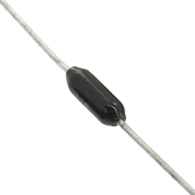
ICGOO电子元器件商城为您提供HVR2500005603FR500由Vishay设计生产,在icgoo商城现货销售,并且可以通过原厂、代理商等渠道进行代购。 HVR2500005603FR500价格参考。VishayHVR2500005603FR500封装/规格:通孔电阻器, 560 kOhms ±1% 0.25W,1/4W 轴向 通孔电阻器 阻燃涂层,高电压,脉冲耐受,安全 金属薄膜。您可以下载HVR2500005603FR500参考资料、Datasheet数据手册功能说明书,资料中有HVR2500005603FR500 详细功能的应用电路图电压和使用方法及教程。
| 参数 | 数值 |
| 产品目录 | |
| 描述 | RES 560K OHM 1/4W 1% AXIAL金属膜电阻器 - 透孔 1/4watt 560Kohms 1% |
| 产品分类 | |
| 品牌 | Vishay / BC ComponentsVishay BC Components |
| 产品手册 | http://www.vishay.com/doc?30260 |
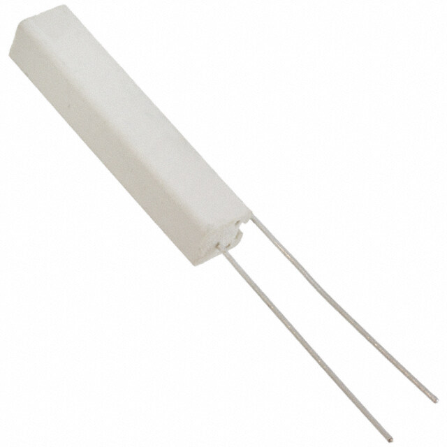
| 产品图片 |
|
| rohs | 符合RoHS无铅 / 符合限制有害物质指令(RoHS)规范要求 |
| 产品系列 | 薄膜电阻器,金属膜电阻器 - 透孔,Vishay / BC Components HVR2500005603FR500HVR25 |
| 数据手册 | |
| 产品型号 | HVR2500005603FR500HVR2500005603FR500 |
| 产品 | Metal Film Resistors High Reliability |
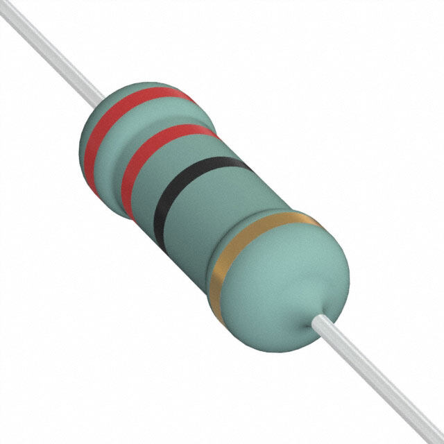
| 产品目录绘图 |
|
| 产品种类 | 金属膜电阻器 - 透孔 |
| 供应商器件封装 | 轴向 |
| 其它名称 | PPCQF560KCT |
| 功率(W) | 0.25W,1/4W |
| 功率额定值 | 250 mW (1/4 W) |
| 包装 | 剪切带 (CT) |
| 商标 | Vishay / BC Components |
| 外壳直径 | 2.5 mm |
| 外壳长度 | 7.5 mm |
| 大小/尺寸 | 0.098" 直径 x 0.256" 长(2.50mm x 6.50mm) |
| 容差 | 1 %±1% |
| 封装/外壳 | 轴向 |
| 工作温度范围 | - 55 C to + 155 C |
| 引线直径 | 0.58 mm |
| 成分 | 金属薄膜 |
| 标准包装 | 1 |
| 温度系数 | 200 PPM / K±250ppm/°C |
| 特性 | 阻燃涂层,脉冲耐受 |
| 电压额定值 | 1.6 kV |
| 电阻 | 560 kOhms |
| 电阻(Ω) | 560k |
| 端子数 | 2 |
| 端接类型 | Axial |
| 类型 | Standard Metal Film Resistors |
| 系列 | HVR25, HVR37 |
| 高度 | - |


PDF Datasheet 数据手册内容提取
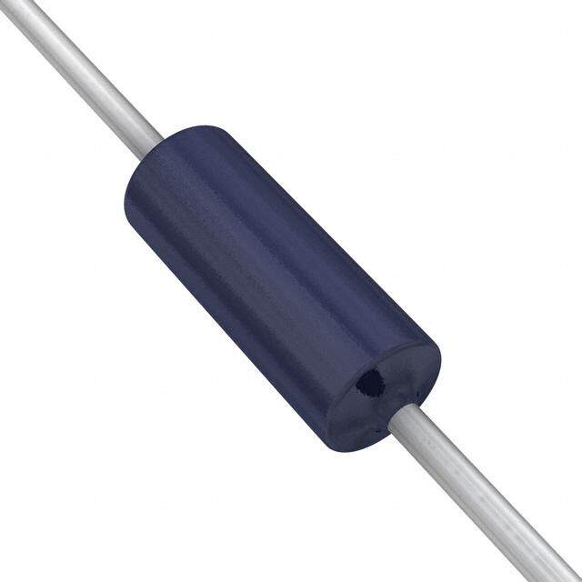
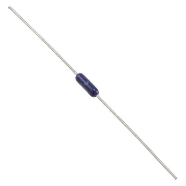
HVR25, HVR37 www.vishay.com Vishay BCcomponents High Ohmic (up to 10 M)/High Voltage (up to 3.5 kV) Metal Film Leaded Resistors FEATURES • Technology: metal film • High pulse loading (up to 10 kV) capability • Small size (0207/0411) • Compatible with lead (Pb)-free and lead containing soldering processes • Material categorization: for definitions of compliance please see www.vishay.com/doc?99912 APPLICATIONS • Power supplies • Electronic ballast DESIGN SUPPORT TOOLS click logo to get started • White goods • Television Models Available A homogenous film of metal alloy is deposited on a high grade ceramic body. After a helical groove has been cut in the resistive layer, tinned electrolytic copper wires are welded to the end-caps. The resistors are coated with a blue, non-flammable lacquer, which provides electrical, mechanical, and climatic protection. TECHNICAL SPECIFICATIONS DESCRIPTION HVR25 HVR37 Resistance range 100 k to 10 M 100 k to 10 M Resistance tolerance ± 5 % ± 1 % ± 5 % ± 1 % E-series E24 series E24/E96 series E24 series E24/E96 series Temperature coefficient 200 ppm/K Climatic category (LCT/UCT/days) 55/155/56 Rated dissipation, P 0.25 W 0.5 W 70 Maximum permissible voltage U max. DC 1600 V 3500 V RMS 1150 V 2500 V Basic specification IEC 60115-1 Stability after: Load (1000 h, P70) ± (5 % R + 0.1 ± (1.5 % R + 0.1 ± (5 % R + 0.1 ± (1.5 % R + 0.1 Long term damp heat test (56 days) ± (1.5 % R + 0.1 ± (1.5 % R + 0.1 ± (1.5 % R + 0.1 ± (1.5 % R + 0.1 Soldering (10 s, 260 °C) ± (1 % R + 0.1 ± (1 % R + 0.1 ± (1 % R + 0.1 ± (1 % R + 0.1 Revision: 11-Jul-2018 1 Document Number: 30260 For technical questions, contact: filmresistorsleaded@vishay.com THIS DOCUMENT IS SUBJECT TO CHANGE WITHOUT NOTICE. THE PRODUCTS DESCRIBED HEREIN AND THIS DOCUMENT ARE SUBJECT TO SPECIFIC DISCLAIMERS, SET FORTH AT www.vishay.com/doc?91000
HVR25, HVR37 www.vishay.com Vishay BCcomponents PART NUMBER AND PRODUCT DESCRIPTION (1) Part Number: HVR2500001503JA100 H V R 2 5 0 0 0 0 1 5 0 3 J A 1 0 0 MODEL/SIZE VARIANT TCR/MATERIAL VALUE TOLERANCE PACKAGING (2) SPECIAL HVR2500 0 = neutral 0 = standard 3 digit value F = 1 % A1 Up to 2 digits HVR3700 1 digit multiplier J = 5 % A5 00 = standard MULTIPLIER R5 3 = *103 N4 4 = *104 5 = *105 Product Description: HVR25 5 % A1 150K HVR25 5 % A1 150K Model TOLERANCE PACKAGING (2) RESISTANCE VALUE HVR25 ± 1 % A1 150K = 150 k HVR37 ± 5 % A5 4M64 = 4.64 M R5 N4 Notes (1) The PART NUMBER is shown to facilitate the introduction of the unified part numbering system (2) Please refer to table PACKAGING, see next page PACKAGING AMMO PACK REEL MODEL TAPING PIECES CODE PIECES CODE 5000 A5 5000 R5 Axial, 52 mm HVR25 1000 A1 Radial 4000 N4 HVR37 Axial, 52 mm 1000 A1 5000 R5 DIMENSIONS L1 Ø D Ø d L2 A DIMENSIONS - Resistor types, mass and relevant physical dimensions L L D Ø d A MASS TYPE 1max. 2 max. max. (mm) (mm) (mm) (mm) (mm) (mg) HVR25 6.5 7.5 2.5 0.58 0.05 52.5 1.5 220 HVR37 10 12 4 0.70 0.03 52.5 1.5 500 Revision: 11-Jul-2018 2 Document Number: 30260 For technical questions, contact: filmresistorsleaded@vishay.com THIS DOCUMENT IS SUBJECT TO CHANGE WITHOUT NOTICE. THE PRODUCTS DESCRIBED HEREIN AND THIS DOCUMENT ARE SUBJECT TO SPECIFIC DISCLAIMERS, SET FORTH AT www.vishay.com/doc?91000
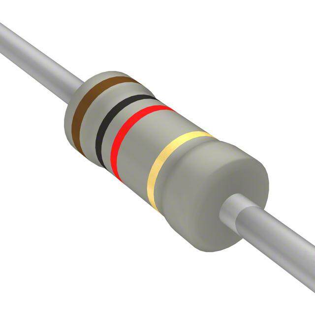
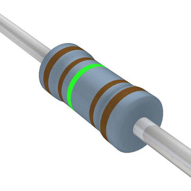
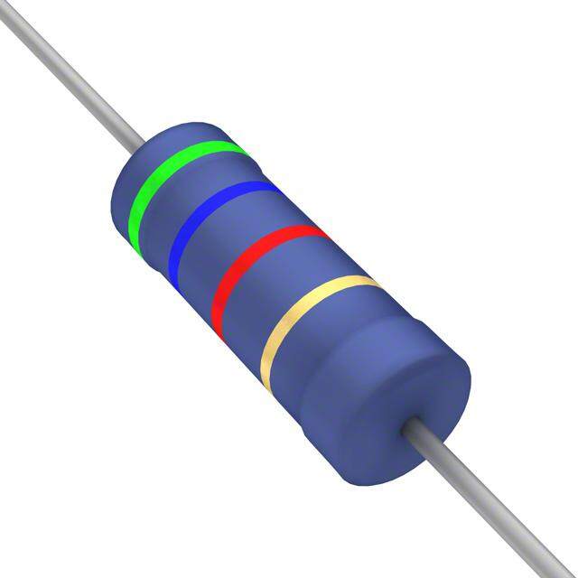
HVR25, HVR37 www.vishay.com Vishay BCcomponents PRODUCTS WITH RADIAL LEADS (HVR25) P2 P H 1 H H0 L L1 W 0 W F P0 P1 D0 DIMENSIONS - Radial taping SYMBOL PARAMETER VALUE TOLERANCE UNIT P Pitch of components 12.7 1.0 mm P0 Feed-hole pitch 12.7 0.2 mm P1 Feed-hole centre to lead at topside at the tape 3.85 0.5 mm P2 Feed-hole center to body center 6.35 1.0 mm F Lead-to-lead distance 4.8 0.7/-0 mm W Tape width 18.0 0.5 mm W Minimum hold down tape width 5.5 - mm 0 H1 Component height 29 Max. mm H Lead wire clinch height 16.5 0.5 mm 0 H Height of component from tape center 19.5 1 mm D0 Feed-hole diameter 4.0 0.2 mm L Maximum length of snipped lead 11.0 - mm L Minimum lead wire (tape portion) shortest lead 2.5 - mm 1 Note • Please refer document number 28721 “Packaging” for more detail MARKING The nominal resistance and tolerance are marked on the resistor using four or five colored bands in accordance with IEC 60062, marking codes for resistors and capacitors. Standard values of nominal resistance are taken from the E24 and E24/E96 series for resistors with a tolerance of 5 % or 1 % respectively. The values of the E24/E96 series are in accordance with IEC 60063. Yellow and grey are used instead of gold and silver because metal particles in the lacquer could affect high-voltage properties. Revision: 11-Jul-2018 3 Document Number: 30260 For technical questions, contact: filmresistorsleaded@vishay.com THIS DOCUMENT IS SUBJECT TO CHANGE WITHOUT NOTICE. THE PRODUCTS DESCRIBED HEREIN AND THIS DOCUMENT ARE SUBJECT TO SPECIFIC DISCLAIMERS, SET FORTH AT www.vishay.com/doc?91000
HVR25, HVR37 www.vishay.com Vishay BCcomponents FUNCTIONAL PERFORMANCE P n o pati100 si s Di er w o P 0 - 55 0 70 155 Ambient temperature ϑ amb Derating - Standard Operation Maximum dissipation (P ) in percentage of rated power as a function of ambient temperature (T ) max. amb PULSE LOADING CAPABILITY Note • Maximum allowed peak pulse voltage in accordance with IEC 60065, 14.1.a; 50 discharges from a 1 nF capacitor charged to U ; max. 12 discharges/min 12 11 10 9 8 V) k (ax. 7 m Û 6 5 HVR25 R = (4.0 % R + 0.1 ) 4 10-2 10-1 100 101 102 R(MΩ) 12 11 10 9 8 V) k (ax. 7 m Û 6 HVR37 5 For 5 % tolerance R = (4.0 % R + 0.1 ) For 1 % tolerance R = (2.0 % R + 0.1 ) 4 10-2 10-1 100 101 102 R(MΩ) Revision: 11-Jul-2018 4 Document Number: 30260 For technical questions, contact: filmresistorsleaded@vishay.com THIS DOCUMENT IS SUBJECT TO CHANGE WITHOUT NOTICE. THE PRODUCTS DESCRIBED HEREIN AND THIS DOCUMENT ARE SUBJECT TO SPECIFIC DISCLAIMERS, SET FORTH AT www.vishay.com/doc?91000
HVR25, HVR37 www.vishay.com Vishay BCcomponents TESTS AND REQUIREMENTS Essentially all tests are carried out in accordance with IEC 60115-1, category 55/155/56 (rated temperature range -55 °C to +155 °C; damp heat, long term, 56 days) and along the lines of IEC 60068-2-xx test method. The tests are carried out under standard atmospheric conditions according to IEC 60068-1, 5.3 unless otherwise specified. In some instances deviations from IEC recommendations were necessary for our method of specifying. PERFORMANCE IEC REQUIREMENTS IEC 60068-2-xx PERMISSIBLE CHANGE (R) 60115-1 TEST PROCEDURE TEST CLAUSE METHOD HVR25 HVR37 Temperature Between 4.8 - 200 ppm/K coefficient -55 °C and +155 °C 1000 h; loaded with P70 or Umax.; 1.5 h on; 0.5 h off 4.25.1 - Endurance at 70 °C for 5 % tolerance (5 % R + 0.1 ) for 1 % tolerance (1.5 % R + 0.1 ) 56 days; 40 °C; 90 % to 95 % RH Damp heat, loaded with 0.01 P 4.24 78 (Cab) 70 steady state for 5 % tolerance (5 % R + 0.1 ) for 1 % tolerance (1.5 % R + 0.1 ) 4.23 Climatic sequence 4.23.2 2 (Ba) Dry heat 16 h, 155 °C Damp heat, 24 h; 25 °C to 55 °C 4.23.3 30 (Db) cyclic 90 % to 100 % RH; 1 cycle (1.5 % R + 0.1 ) 4.23.4 1 (Aa) Cold 2 h, -55 °C Damp heat, 5 days; 25 °C to 55 °C 4.23.6 30 (Db) (accelerated) 90 to 100 % RH remaining cycles 30 min at LCT; 30 min at UCT; Rapid change of No visual damage 4.19 14 (Na) LCT = -55 °C; temperature (1 % R + 0.1 ) UCT = 155 °C; 5 cycles Room temperature; dissipation 6.25 x P 70 (voltage not more than 2 x limiting voltage, 4.13 - Short time overload 10 000 V ); max. 10 cycles 5 s on and 45 s off for 5 % tolerance (2 % R + 0.1 ) for 1 % tolerance (1 % R + 0.1 ) 4.12 - Noise IEC 60195 Max. 5 μV/V Max. 2.5 μV/V Robustness of 4.16 terminations: 4.16.2 21 (Ua1) Tensile all samples Load 10 N; 10 s No damage 4.16.3 21 (Ub) Bending half number Load 5 N; 4 x 90° (1 % R + 0.1 ) of samples Torsion other half of 4.16.4 21 (Uc) 3 x 360° in opposite direction samples Frequency 10 Hz to 500 Hz; displacement 4.22 6 (Fc) Vibration 1.5 mm or acceleration 10 g; (1.0 % R+ 0.1 ) 3 directions; total 6 h (3 x 2 h) Revision: 11-Jul-2018 5 Document Number: 30260 For technical questions, contact: filmresistorsleaded@vishay.com THIS DOCUMENT IS SUBJECT TO CHANGE WITHOUT NOTICE. THE PRODUCTS DESCRIBED HEREIN AND THIS DOCUMENT ARE SUBJECT TO SPECIFIC DISCLAIMERS, SET FORTH AT www.vishay.com/doc?91000
HVR25, HVR37 www.vishay.com Vishay BCcomponents PERFORMANCE IEC REQUIREMENTS IEC 60068-2-xx PERMISSIBLE CHANGE (R) 60115-1 TEST PROCEDURE TEST CLAUSE METHOD HVR25 HVR37 2 s; 235 °C: Solder bath method; Good tinning Solderability SnPb40 4.17 20 (Ta) ( 95 % covered); (after aging) 3 s; 245 °C: Solder bath method; no visible damage SnAg3Cu0.5 Resistance to Thermal shock: 10 s; 260 °C; 4.18 20 (Tb) (1 % R + 0.1 ) soldering heat 3 mm from body Component solvent 4.29 45 (XA) Isopropyl alcohol No visible damage resistance U = 500 V DC 4.6.11 - Insulation resistance during 1 min, Rins min. 104 M V-block method U = 700 V Voltage proof on RMS 4.7 - during 1 min, No flashover or breakdown insulation V-block method 12NC INFORMATION FOR HISTORICAL CODING REFERENCE ONLY • The resistors have a 12 digit ordering code starting with Last Digit of 12NC Indicating Resistance Decade 2306 • The next 4 or 5 digits indicate the resistor type and RESISTANCE RESISTANCE LAST DIGIT DECADE (5 %) DECADE (1 %) packaging • For 5 % tolerance the last 3 digits indicate the resistance 100 k to 910 k 100 k to 976 k 4 value: 1 M to 9.1 M 1 M to 9.76 M 5 - The first 2 digits indicate the resistance value - The last digit indicates the resistance decade in = 10 M = 10 M 6 accordance with table 12NC Example • For 1 % tolerance the last 4 digits indicate the resistance HVR25, 150 k, 5 %, ammopack 1000 pieces is value: 2306 241 13154 - The first 3 digits indicate the resistance value - The last digit indicates the resistance decade in accordance with table 12NC - resistor type and packaging 2306 ... ..... DESCRIPTION BANDOLIER BANDOLIER IN AMMOPACK ON REEL RADIAL TAPED TYPE TAPE WIDTH TOLERANCE 1000 UNITS 5000 UNITS 5000 UNITS 4000 UNITS 5 % 241 36... 241 13... 241 53... 241 23.... HVR25 52.5 1 % 241 0.... 241 8.... 241 7.... 241 6.... 5 % - 242 13... - 242 23... HVR37 52.5 1 % - 242 8.... - 242 6.... Revision: 11-Jul-2018 6 Document Number: 30260 For technical questions, contact: filmresistorsleaded@vishay.com THIS DOCUMENT IS SUBJECT TO CHANGE WITHOUT NOTICE. THE PRODUCTS DESCRIBED HEREIN AND THIS DOCUMENT ARE SUBJECT TO SPECIFIC DISCLAIMERS, SET FORTH AT www.vishay.com/doc?91000
Legal Disclaimer Notice www.vishay.com Vishay Disclaimer ALL PRODUCT, PRODUCT SPECIFICATIONS AND DATA ARE SUBJECT TO CHANGE WITHOUT NOTICE TO IMPROV E RELIABILITY, FUNCTION OR DESIGN OR OTHERWISE. Vishay Intertechnology, Inc., its affiliates, agents, and employees, and all persons acting on its or their behalf (collectively, “Vishay”), disclaim any and all liability for any errors, inaccuracies or incompleteness contained in any datasheet or in any other disclosure relating to any product. Vishay makes no warranty, representation or guarantee regarding the suitability of the products for any particular purpose o r the continuing production of any product. To the maximum extent permitted by applicable law, Vishay disclaims (i) any and all liability arising out of the application or use of any product, (ii) any and all liability, including without limitation special, consequential or incidental damages, and (iii) any and all implied warranties, including warranties of fitness for particular purpose, non-infringement and merchantability. Statements regarding the suitability of products for certain types of applications are based on Vishay’s knowledge of typical requirements that are often placed on Vishay products in generic applications. Such statements are not binding statements about the suitability of products for a particular application. It is the customer’s responsibility to validate that a particular product with the properties described in the product specification is suitable for use in a particular application. Parameters provided in datasheets and / or specifications may vary in different applications and performance may vary over time. All operating parameters, including typical parameters, must be validated for each customer application by the customer’s technical experts. Product specifications do not expand or otherwise modify Vishay’s terms and conditions of purchase, including but not limited to the warranty expressed therein. Except as expressly indicated in writing, Vishay products are not designed for use in medical, life-saving, or life-sustainin g applications or for any other application in which the failure of the Vishay product could result in personal injury or death. Customers using or selling Vishay products not expressly indicated for use in such applications do so at their own risk . Please contact authorized Vishay personnel to obtain written terms and conditions regarding products designed for such applications. No license, express or implied, by estoppel or otherwise, to any intellectual property rights is granted by this documen t or by any conduct of Vishay. Product names and markings noted herein may be trademarks of their respective owners. © 2019 VISHAY INTERTECHNOLOGY, INC. ALL RIGHTS RESERVED Revision: 01-Jan-2019 1 Document Number: 91000
Mouser Electronics Authorized Distributor Click to View Pricing, Inventory, Delivery & Lifecycle Information: V ishay: HVR3700003573FR500 HVR2500001004FR500 HVR2500001783FR500 HVR2500002003FR500 HVR2500003163FR500 HVR2500003833FR500 HVR2500003903FR500 HVR2500004533FR500 HVR2500005603FR500 HVR2500006983FR500 HVR2500007873FR500 HVR3700001004FR500 HVR3700001005FR500 HVR3700001073FR500 HVR3700001183FR500 HVR3700001244FR500 HVR3700001654FR500 HVR3700001803FR500 HVR3700002204FR500 HVR3700002323FR500 HVR3700002703FR500 HVR3700003003FR500 HVR3700003603FR500 HVR3700004224FR500 HVR3700004324FR500 HVR3700005103FR500 HVR3700005113FR500 HVR3700005493FR500 HVR3700005903FR500 HVR3700007153FR500 HVR3700007504FR500 HVR3700008204FR500 HVR2500009093FR500 HVR3700001003FR500 HVR3700002204FA100 HVR3700004753FA100 HVR2500003303FR500 HVR3700002493FR500 HVR3700002494FR500 HVR3700002703JR500 HVR3700002704FR500 HVR3700002704JR500 HVR2500002204JA100 HVR2500001504JA100 HVR3700002204JA100 HVR2500004704JA100 HVR2500001005JA100 HVR2500001204JA100 HVR3700001005JA100 HVR3700004704JA100 HVR3700001504JA100 HVR3700009104FR500 HVR3700009534FR500 HVR3700004703FR500 HVR3700001204FR500 HVR3700001204JA100 HVR2500001004JR500 HVR3700007683FR500 HVR3700007874FR500 HVR3700008203FR500 HVR3700008203JR500 HVR3700008254FR500 HVR3700009094FR500 HVR3700005104FR500 HVR3700006803FR500 HVR3700006803JR500 HVR3700006804FR500 HVR3700006804JR500 HVR3700007503FR500 HVR3700004644FR500 HVR3700004703JR500 HVR3700004704FR500 HVR3700004704JR500 HVR3700004993FR500 HVR3700004994FR500 HVR3700003904FR500 HVR3700003904JR500 HVR3700003924FR500 HVR3700004024FR500 HVR3700004303FR500 HVR3700004304JR500 HVR3700003323FR500 HVR3700003324FR500 HVR3700003604FR500 HVR3700003744FR500 HVR3700003903FR500 HVR3700003903JR500 HVR3700003014FR500 HVR3700003164FR500 HVR3700003303FR500 HVR3700003303JR500 HVR3700003304FR500 HVR3700003304JR500 HVR3700002203JR500 HVR3700002204JR500 HVR3700002214FR500 HVR3700002403JR500 HVR3700002404FR500 HVR3700003004FR500 HVR3700001804FR500