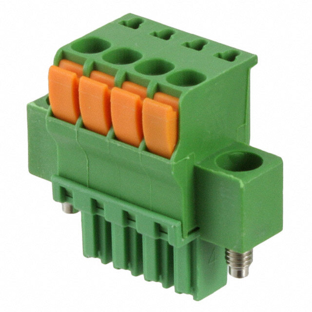
ICGOO在线商城 > HR31-5.08P-5SC(71)
- 型号: HR31-5.08P-5SC(71)
- 制造商: Hirose Electric
- 库位|库存: xxxx|xxxx
- 要求:
| 数量阶梯 | 香港交货 | 国内含税 |
| +xxxx | $xxxx | ¥xxxx |
查看当月历史价格
查看今年历史价格
HR31-5.08P-5SC(71)产品简介:
ICGOO电子元器件商城为您提供HR31-5.08P-5SC(71)由Hirose Electric设计生产,在icgoo商城现货销售,并且可以通过原厂、代理商等渠道进行代购。 提供HR31-5.08P-5SC(71)价格参考以及Hirose ElectricHR31-5.08P-5SC(71)封装/规格参数等产品信息。 你可以下载HR31-5.08P-5SC(71)参考资料、Datasheet数据手册功能说明书, 资料中有HR31-5.08P-5SC(71)详细功能的应用电路图电压和使用方法及教程。
| 参数 | 数值 |
| 产品目录 | |
| 描述 | CONN HOUSING 5POS 5.08MM CRIMP集管和线壳 HSNG 5P 5.08MM CRIMP |
| 产品分类 | |
| 品牌 | Hirose Electric Co Ltd |
| 产品手册 | |
| 产品图片 |
|
| rohs | 符合RoHS无铅 / 符合限制有害物质指令(RoHS)规范要求 |
| 产品系列 | Hirose Connector HR31-5.08P-5SC(71)HR31 |
| 数据手册 | |
| 产品型号 | HR31-5.08P-5SC(71) |
| 产品目录绘图 |
|
| 产品目录页面 | |
| 产品种类 | 集管和线壳 |
| 产品类型 | Wire Housings |
| 位置数量 | 5 |
| 其它名称 | *HR31-5.08P-5SC(71) |
| 包装 | 散装 |
| 商标 | Hirose Connector |
| 备注 | 不提供触点 |
| 外壳材料 | Polybutylene Terephthalate (PBT) |
| 安装类型 | 自由悬挂 |
| 安装角 | Right |
| 安装风格 | - |
| 工作温度范围 | - 40 C to + 100 C |
| 工厂包装数量 | 1 |
| 排数 | 1 |
| 排距 | - |
| 标准包装 | 25 |
| 特性 | - |
| 电压额定值 | 250 V, 350 V |
| 电流额定值 | 12 A, 10 A |
| 相关产品 | /product-detail/zh/HR31-SC-121(71)/H11446-ND/1202872/product-detail/zh/HR31-SC-111(71)/H11445-ND/1202871/product-detail/zh/HR31-SC-123/H4118-ND/572171/product-detail/zh/HR31-SC-121/H4117-ND/572170/product-detail/zh/HR31-SC-113/H4116-ND/572169/product-detail/zh/HR31-SC-111/H4115-ND/572168 |
| 端接类型 | - |
| 类型 | Plug Housing |
| 系列 | HR31 |
| 紧固类型 | 螺钉锁 |
| 绝缘电阻 | 1000 MOhms |
| 节距 | 5.08 mm |
| 触头端接 | 压接 |
| 触头类型 | 母形插口 |
| 触点材料 | Steel |
| 触点电镀 | Nickel |
| 触点类型 | Pin (Male) |
| 连接器类型 | 插头 |
| 配套产品 | /product-detail/zh/HR31-5.08R-5PDL(72)/H11444-ND/1202870/product-detail/zh/HR31-5.08R-5PD(72)/H11443-ND/1202869/product-detail/zh/HR31-5.08R-5PDL(01)/H4114-ND/572167/product-detail/zh/HR31-5.08R-5PDL/H4113-ND/572166/product-detail/zh/HR31-5.08R-5PD(01)/H4112-ND/572165/product-detail/zh/HR31-5.08R-5PD/H4111-ND/572164 |
| 针脚数 | 5 |
| 间距 | 0.200"(5.08mm) |
| 颜色 | 黑 |




- 商务部:美国ITC正式对集成电路等产品启动337调查
- 曝三星4nm工艺存在良率问题 高通将骁龙8 Gen1或转产台积电
- 太阳诱电将投资9.5亿元在常州建新厂生产MLCC 预计2023年完工
- 英特尔发布欧洲新工厂建设计划 深化IDM 2.0 战略
- 台积电先进制程称霸业界 有大客户加持明年业绩稳了
- 达到5530亿美元!SIA预计今年全球半导体销售额将创下新高
- 英特尔拟将自动驾驶子公司Mobileye上市 估值或超500亿美元
- 三星加码芯片和SET,合并消费电子和移动部门,撤换高东真等 CEO
- 三星电子宣布重大人事变动 还合并消费电子和移动部门
- 海关总署:前11个月进口集成电路产品价值2.52万亿元 增长14.8%

PDF Datasheet 数据手册内容提取
Interface Connectors for Factory Automation Network HR31 Series Complies with DeviceNet requirements Comparison of plug heights ●Hirose HR31 2 0. 1 ●Other manufacturer’s product d. e v r e s e 15 R s ht g Ri All ■ Features D. T 1. DeviceNet Compliant L O., Conforms to requirements of Factory Automation Network DeviceNet standards. C Hirose products are distinct from products of made others, as described below. C RI Feature Made by others Hirose HR31 T C Crimped to commercially available cap Reduced number of termination Crimped and connected to terminal then E connectors, inserted into housing and L operations fastened simply by inserting into housing. E fastened by screw. (*) E Plug height is 10.2 mm, allowing use of less S High density mounting Plug height : 15 mm O space when mounting several connectors R HI Prevention of connection errors Contact positions not identifi ed. Permanently identifi ed contact positions 8 Number of required operations Connectors are attached by screws from No need for screws, built-in locking pin secures 1 to secure receptacle assembly 0 the opposite side. connector to the board 2 to the board ht g * Although it is possible to terminate discrete cables with screws and not use a pin contact, however, there is the potential issue yri and concern for long-term reliability and problems. Therefore, most users prefer to use crimp contacts. p o C 2. Screw-lock style Total space occupied by mated 8 The screw lock style connector features secure mating and assemblies 1 0 a higher locking force retention. 2 c.1. 3. Snap-lock Style De The snap lock plug features a structure that creates a tactile With screw lock click during mating. 4. Commercially available tools may be used 12 20 Use crimp tools conforming to JIS C 9711 standards. Terminated contacts can be removed using 1 mm dia. steel 5 pin. and re-inserted. 35.5 234 27 5. Protected contacts 1 When installed, the crimped contacts are protected completely by the plug housing. This design eliminates the risk of damaging the contacts. 0.2 1 Ipnl ecaassee sc ownhtaecret ath ceo ampppalincya trieopnr ewsielln dteamtivaen fdo ar fhuirgthh eler vineflo orfm raetliiaobni.lity, such as automotive, 2014.12w 1
HR31 Series●Interface Connectors for Factory Automation Network Product Specification 12A (2.5mm2 wire) Current rating Operating temperature range -40ç to +100ç Rating 10A (1.5mm2 wire) Voltage rating 250V AC, 350V DC Storage temperature range -40ç to +85ç Item Specifi cation Conditions 1.Contact resistance 5 mø max. 1A DC 2.Insulation resistance 1000 Mø min. 500 V DC 3.Withstanding voltage No fl ashover or insulation breakdown 2000V AC/one minute Standard waveform of 4KV, positive/negative, 4.Impulse withstanding voltage No fl ashover or insulation breakdown 3 times each Frequency: 10 to 55 Hz, single amplitude of 5.Vibration No electrical discontinuity of 10 µs or more 0.75 mm, 5 min. in each of the 3 directions, 10 cycles each d. 6. Durability Contact resistance: 10 mø max. e 1000 cycles v (insertion/ withdrawal) r e s Temperature: -40ç / Room temperature to e R +100ç / Room temperature s 7. Temperature cycle Insulation resistance: 1000 Mø min. Time: 30 / 10 to 15 / 30 / 10 to 15 (Minutes) ht g 5 cycles Ri Insulation resistance: All 8.Humidity 10 Mø min. (Humidity state) 96 hours at temperature of 40ç and humidity D. 100 Mø min. (Dry state) of 90% to 95% T L O., Materials C C Part Material Finish Remarks RI Insulator PBT Color: Black or Green UL94V-0 T Plug C Screw Steel Nickel plating ––––– E Contact area: phosphor bronze Contact area: gold plating L Crimp contact Socket contact ––––– E Termination area: copper Termination area: tin plating E S Insulator PBT Color: Black or Green UL94V-0 O Contact area: gold plating R Male contact Brass ––––– HI Receptacle Termination are: gold plating 8 Nut Steel Nickel plating ––––– 1 Board retention pin Phosphor bronze Tin plating Board retention pin 0 2 ht g ri Ordering information y p o ●Connector C 8 HR31 - 5.08 P A - 5 S C ( 01) 1 0 2 q w e r t y u i 1. c. qModel name HR31 uTerminal type De wContact pitch 5.08mm C: Crimping eConnector type P: Plug DL: Right angle through hole type R: Receptacle D: Straight through hole type rScrew lock type Blank: With screw iOther specifications: A two-digit number A: Without screw such as (01) or (02) is tNumber of contacts 5 added to indicate yContact type other specifications. S: Female contact P: Male contact ●Crimp contact HR31 - SC - 1 1 1 ( 01) o !0 !1 !2 !3 !4 oModel name HR31 !3Plating type !0Contact type SC: female contact 1: Gold plating !1Contact packaging type 1: loose contact !4Other specifications: A two-digit number !2Conductor cross area such as (01) or (02) is 1: 1.04 to 2.63mm2 added to indicate 2: 0.2 to 1.65mm2 other specifications. 2
HR31 Series●Interface Connectors for Factory Automation Network 27 Plug (with screw lock) 5 4 3 2 1 3 8. 2 3 8. 25.4 35.5 ed. HR31-5.08P-5SC 10.2 v r e s e Part No. HRS No. Weight Color R s HR31-5.08P-5SC(72) 131-0002-2 72 8g Green ht g Ri Crimp contact B All 23 B - B D. LT 35 ØA O., 2. C B C RI Part No. HRS No. ØA Weight Contact plating Applicable conductor cross area (Note 2) T HR31-SC-111(71) 131-0004-8 71 4 1.04 to 2.63mm2 C 1g Gold HR31-SC-121(71) 131-0005-0 71 3.3 0.2 to 1.65mm2 E L E Note 1: Packaging (100 pcs/pack) E Note 2: For a multi-strand conductors S O R Receptacle (Right angle through hole type with screw lock) HI 8 1 0 2 ht g ri y Connector mounting side p o C 8 35.5 12 1 1.20 8.6 1 2 3 4 5 Dec. 3.33 71.50 HR31-5.08R-5PDL Part No. HRS No. Weight Color Contact plating Board retention pin HR31-5.08R-5PDL(72) 131-0001-0 72 Black 4g Gold With HR31-5.08R-5PDL(75) 131-0001-0 75 Green PCB mounting pattern ● With screw lock 7.5±0.05 5-Ø1.6+ 00.1 (Through hole) 2-Ø2.3+ 00.1 (Through hole) 5 0 0. ± 0 1 5.08±0.05 5.08±0.05 10.16±0.05 10.16±0.05 15.24±0.05 15.24±0.05 Connector mounting side (Board thickness =1.6) 3
HR31 Series●Interface Connectors for Factory Automation Network Receptacle (Straight through hole type with screw lock) 35.5 6 1 2 3 4 5 8. 3.8 12 4.3 d. HR31-5.08R-5PD Connector mounting side B e v r e s Part No. HRS No. Weight Color Contact plating Board retention pin e R HR31-5.08R-5PD(76) 131-0003-5 76 4g Green Gold Without s ht g PCB mounting pattern Ri All ● With screw lock CO., LTD. 5-Ø1.6+ 0 .01 (Through hole) C RI 5 CT ±0.0 E 8 L 3. 5.08±0.05 5.08±0.05 E E 10.16±0.05 10.16±0.05 S O Connector mounting side B R HI (Board thickness =1.6) 8 1 0 2 ht g ri y p o C 8 1 0 2 1. c. e D 4
HR31 Series●Interface Connectors for Factory Automation Network Tools Type Part No. HRS No. Manual crimp tool HR31-TC-01 902-1512-4 Contact removal pin HR31-SC-TP 150-0215-1 d. e Manual crimp tool Contact removal pin v r e s e R s ● Tools application procedures ht g Ri 1. Manual contact crimp tool All The tool will terminate all specified crimp contacts. Placement of correct contact in D. corresponding crimp position on the tool is critical. The positions are clearly indicated on the tool T as (2) and (1.25). The exposed conductor strip length is 5mm. L O., Crimp position indicator Applicable crimp contact C 2 HR31-SC-111 C RI 1.25 HR31-SC-121 T C Crimp position indicator E L E E S O R 5 HI 2 8 .1 2 1 0 2 ht g ri y p o C 8 2. Contact removal/extraction 1 0 2 Wiring errors can be corrected by removing the crimp contacts using the extraction tool and the 1. c. following procedure. e D 1) Insert the extraction tool from the underside of connector and apply pressure onto the mold lance. (Fig.1) 2) While pressing on the mold lance, angle the extraction tool and release the disconnection prevention mechanism on the crimping contact. (Fig.2) 3) Remove the extraction tool. 4) Pull the wire rearward to disconnect and remove the contact. Mold lance Mold lance Wire Wire Pull-out Insertion direction Contact removal pin Contact removal pin 5
HR31 Series●Interface Connectors for Factory Automation Network Usage Precautions 1. To prevent damage, align receptacle with the panel and board in such a way that it is not subject to excess loads. 1.1 Recommended mounting panel dimensions (right angle through hole type) Panel 5 min. A Part No. A 3.2+ 00.2 16.6±0.1 HR31-5.08R-5PDL(**) 36++00.2 ed. 2+ 00.2 v r e s e hts R +0.28 0 +0.211 0 g 7. Ri All D. Board T L O., 1.2 Recommended mounting panel dimensions (straight through hole type) C C RI T C Panel Part No. B E 5 min. B L HR31-5.08R-5PD(**) 36+0.2 E +0 E 3.2 16.6±0.1 S 2+ 00.2 O R HI 2018 +0.28 0 +0.211 0 ht 7. g yri +0.2 0 p 2 o 0. C 8 1 0 2 2. Insert the crimp contact into the plug in the direction shown below. 1. c. e Crimp contact Wire D 3. Use a number 0 cross drive bit to tighten the screw lock’s screw. 4. Assure that the circuit’s power is off when mating and un-mating connectors. ® 2-6-3,Nakagawa Chuoh,Tsuzuki-Ku,Yokohama-Shi 224-8540,JAPAN TEL: +81-45-620-3526 Fax: +81-45-591-3726 http://www.hirose.com http://www.hirose-connectors.com The characteristics and the specifications contained herein are for reference purpose. Please refer to the latest customer drawings prior to use. 6 The contents of this catalog are current as of date of 12/2014. Contents are subject to change without notice for the purpose of improvements. Powered by TCPDF (www.tcpdf.org)
Mouser Electronics Authorized Distributor Click to View Pricing, Inventory, Delivery & Lifecycle Information: H irose Electric: HR31-5.08R-5PDL(72) HR31-5.08R-5PDL(75) HR31-5.08R-5PDL(76) HR31-5.08P-5SC(71) HR31-5.08P-5SC(72) HR31-5.08R-5PD(75) HR31-5.08R-5PD(76) HR31-SC-111(71) HR31-SC-121(71) HR31-SC-TP HR31-TC-01
.jpg)
 Datasheet下载
.JPG)

