ICGOO在线商城 > 传感器,变送器 > 磁性传感器 - 罗盘,磁场(模块) > HMR3500
 Datasheet下载
- 型号: HMR3500
- 制造商: Honeywell Solid State Electronics
- 库位|库存: xxxx|xxxx
- 要求:
| 数量阶梯 | 香港交货 | 国内含税 |
| +xxxx | $xxxx | ¥xxxx |
查看当月历史价格
查看今年历史价格
HMR3500产品简介:
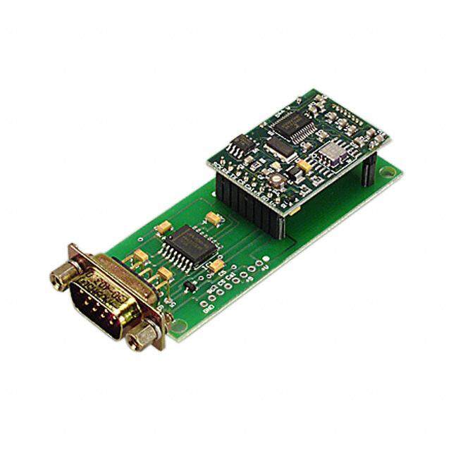
ICGOO电子元器件商城为您提供HMR3500由Honeywell Solid State Electronics设计生产,在icgoo商城现货销售,并且可以通过原厂、代理商等渠道进行代购。 HMR3500价格参考。Honeywell Solid State ElectronicsHMR3500封装/规格:磁性传感器 - 罗盘,磁场(模块), ±700 mGauss, ±180° (X), ±80° (Y) Compass X, Y, Z 450 µGauss, 0.04° Module (No Case)。您可以下载HMR3500参考资料、Datasheet数据手册功能说明书,资料中有HMR3500 详细功能的应用电路图电压和使用方法及教程。
| 参数 | 数值 |
| 产品目录 | |
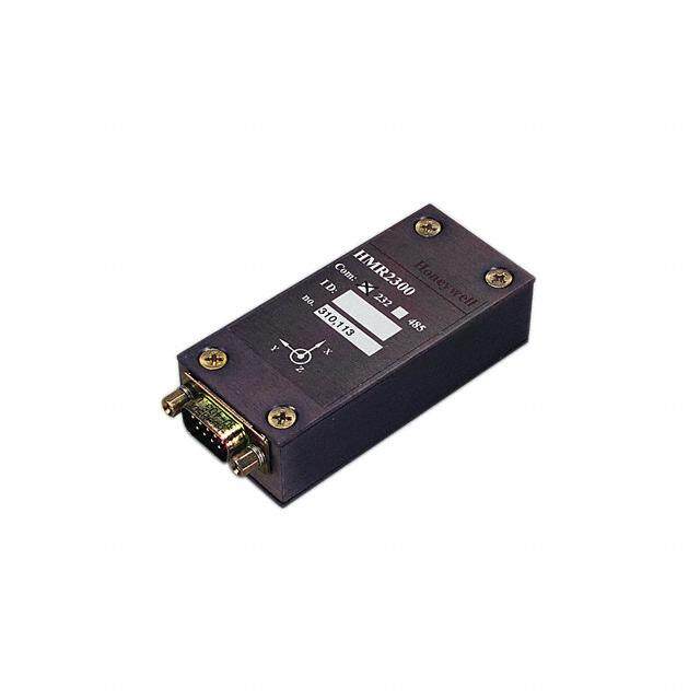
| 描述 | 3-AXIS COMPASS MODULE |
| 产品分类 | |
| 品牌 | Honeywell Microelectronics & Precision Sensors |
| 数据手册 | http://www.honeywell.com/sites/servlet/com.merx.npoint.servlets.DocumentServlet?docid=D17D945AC-C590-6BB5-B8AF-E7B19FB69D8E |
| 产品图片 |
|
| 产品型号 | HMR3500 |
| rohs | 含铅 / 不符合限制有害物质指令(RoHS)规范要求 |
| 产品系列 | TruePoint™ |
| 产品培训模块 | http://www.digikey.cn/PTM/IndividualPTM.page?site=cn&lang=zhs&ptm=4082http://www.digikey.cn/PTM/IndividualPTM.page?site=cn&lang=zhs&ptm=26237http://www.digikey.cn/PTM/IndividualPTM.page?site=cn&lang=zhs&ptm=30104 |
| 产品目录页面 | |
| 其它名称 | 342-1058 |
| 分辨率 | 450 µ高斯, 0.04° |
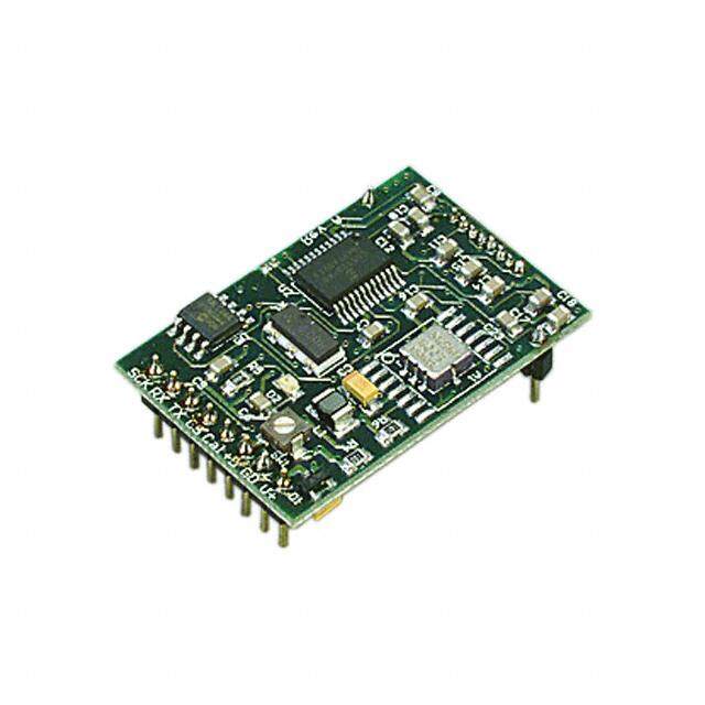
| 封装/外壳 | 模块(无外壳) |
| 接口 | RS-232 |
| 标准包装 | 1 |
| 测量范围 | ±700 微高斯, ±180° (X), ±80° (Y) |
| 特色产品 | http://www.digikey.cn/product-highlights/cn/zh/honeywell-micro-digital-compassing-solutions/3663 |
| 用于测量 | 制导,间距和卷 |
| 类型 | 数字罗盘 |
| 轴 | X,Y,Z |
| 配用 | /product-detail/zh/HMR3500%20DEMO/342-1059-ND/1692483 |


- 商务部:美国ITC正式对集成电路等产品启动337调查
- 曝三星4nm工艺存在良率问题 高通将骁龙8 Gen1或转产台积电
- 太阳诱电将投资9.5亿元在常州建新厂生产MLCC 预计2023年完工
- 英特尔发布欧洲新工厂建设计划 深化IDM 2.0 战略
- 台积电先进制程称霸业界 有大客户加持明年业绩稳了
- 达到5530亿美元!SIA预计今年全球半导体销售额将创下新高
- 英特尔拟将自动驾驶子公司Mobileye上市 估值或超500亿美元
- 三星加码芯片和SET,合并消费电子和移动部门,撤换高东真等 CEO
- 三星电子宣布重大人事变动 还合并消费电子和移动部门
- 海关总署:前11个月进口集成电路产品价值2.52万亿元 增长14.8%
PDF Datasheet 数据手册内容提取
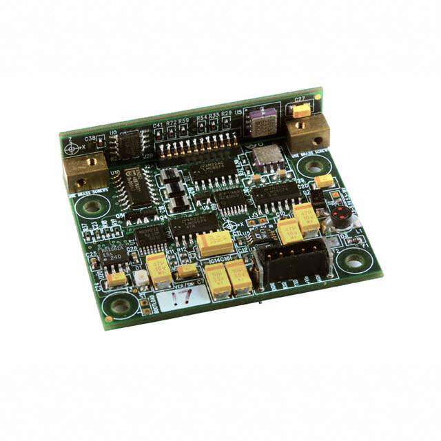
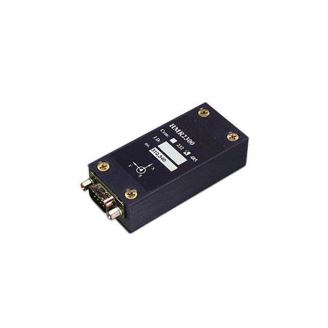
TruePoint™ Compass Module HMR3500 The HMR3500 TruePoint™ compass module is a 3-axis digital compass solution with a customizable coordinate system for mounting in any desired orientation. Three Anisotropic Magneto-Resistive sensors and three MEMs accelerometers are combined to provide compass heading as well as pitch and roll angles. The HMR3500 has provisions for hard and soft-iron correction algorithms to handle magnetic distortion effects. In addition a World Magnetic Model feature is provided to automatically add declination angle corrections for reference to true north (geographic north). Honeywell provides product excellence and performance by introducing innovative solid-state magnetic sensor solutions. These are highly reliable, top performance products that are delivered when promised. Honeywell’s magnetic sensor products provide real solutions you can count on. FEATURES BENEFITS 4 Precision Compass Accuracy 4 Better Than 1° Nominal Heading Accuracy (1)s , 0.1° Resolution 4 Tilt-Compensated 4 ±89° Pitch and Roll, 360° Continuous Roll Capabilit y 4 Update Rate to 25Hz 4 Rapid Heading Computations for Guidance Applications 4 Compact Solution in a 1.97” by 1.65” by 4 Small Size for Tight Mounting Conditions, Minimal Layout Constraints 0.52” PCB Assembly 4 Hard and Soft-Iron Compensation 4 User Driven Calibration to Null Stray Fields. A Single Routine for Both Routines Hard and Soft Iron Corrections 4 World Magnetic Model Included 4 Choice of True North or Magnetic North References 4 -40° to +85°C Operating Temp Range 4 Consumer and Industrial Environment Uses 4 +5 DC Supply Voltage Range 4 Customizable to a Wide Variety of Power Sources 4 Light Weight 4 3.0 oz with Aluminum Housing, 0.6 oz PCB only 4 Customizable Coordinate System 4 24 Custom Coordinate Orientations 4 All Solid State Components 4 Rugged for User-Defined Orientation Plane
HMR3500 SPECIFICATIONS Characteristics Conditions Min Typ Max Units Heading Accuracy (Clean Magnetic Environment) Level - 0.5 1 (1 σ) Pitch 0° to – 30° 0.75 Roll 0° to – 30° 0.75 Resolution 0.1 deg Repeatability 3 sweeps, 0º to 360º, level 0.2 deg σ Pitch and Roll Roll Range Default orientation, rotation about X-axis – 180° deg Pitch Range Default orientation, rotation about Y-axis – 80° deg Accuracy Roll ±30º, Pitch ±30º 0.5 1 deg σ Null Accuracy1 Level ±0.5 deg Resolution Level, 1-sigma, 100 readings 0.04 deg Roll Repeatability Roll ±70º 0.2 deg σ Pitch ±70º 0.2 Pitch Repeatability Roll ±70º 0.1 deg σ Pitch ±70º 0.1 Magnetic Field Range Maximum Magnetic Flux Density 0.7 gauss Resolution 1-sigma, 100 readings 0.45 milli-gauss Dip Angle Earth’s Vertical Field Component -70 +70 deg Linearity 0.2 %FS Electrical Input Voltage Standard Product 2.5 5.0 5.2 volts DC Power Input Voltage 2.5 to 5.2V 300 mW Digital Interface UART ASCII 4800 9600 38,400 Baud Update Rate Continuous Heading Updates 0.05 10 25 Hz Format Bi-directional binary packet data protocol. RS-232 - Physical Dimensions Circuit Board Assembly 1.97 x 1.65 inches x 0.52 Weight HMR3500 PCB only 0.6 ounce HMR3500 with case, no cable 3.0 ounces Connector 5-pin, 2mm pin spacing - Environment Temperature Operating -40 - +85 °C Storage (OEM only) -55 - +125 °C 1 Null zeroing prior to use of the HMR3500 and upon exposure to temperature excursions beyond the Operating Temperature limits is required to achieve highest performance. * Tested at 25°C unless stated otherwise. 2 www.honeywell.com
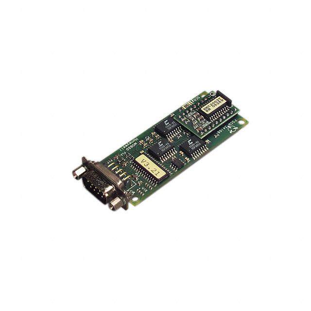
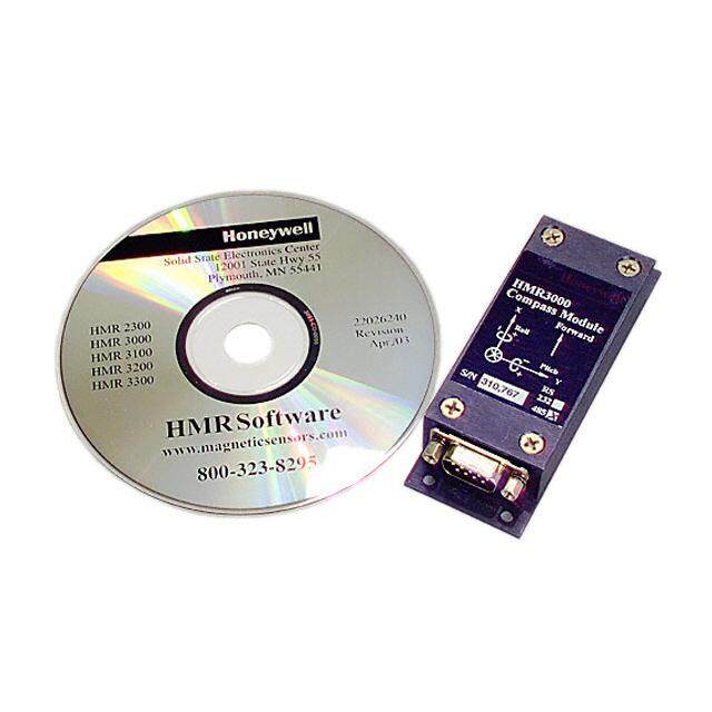
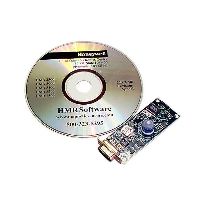
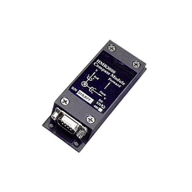
HMR3500 PIN CONFIGURATION Pin Number Pin Name Description 1 Ground Power Supply Return and Ground Reference 2 RXD RS-232 Receive Data 3 TXD RS-232 Transmit Data 4 +Vin Positive Power Supply Voltage Input 5 Ground Ground Reference (for twisted pair routing with +Vin) BASIC DEVICE OPERATION The HMR3500 TruePoint™ Compass Module includes 3-axis Anisotropic Magneto-Resistive (AMR) sensors, 3-axis MEMS accelerometers, a temperature sensor, and 16-bit microprocessor with onboard Analog to Digital Converter (ADC). The HMR3500 is available as a printed circuit board assembly, or assembled in a black aluminum case with cable assembly. Additionally, the cable assembly can be ordered separately. A demonstration kit of the HMR3500 is available with the case, cable assembly, a CD of the CompassHost windows utility software for the user’s personal computer. The HMR3500 requires an external DC power supply for the red (positive) and black (ground) wires of the cable assembly. By feeding 5 volts at about 50 milli-amperes into the HMR3500, the compass will operate, and a red LED on the printed circuit board assembly will begin blinking at a 1Hz rate. Lack of a blinking LED or at a rapid rate is an indication of an error, and action should taken to cycle power on the compass electronics to reset the module. As a factory default, the RS-232 interface is set at 9600 baud with one start bit, 8 data bits, one stop bit, and no parity bits. The HMR3500 does not require any hardware or software handshaking or related features. The baud rate can be changed by command after initial communication at the current baud rate. The CompassHost utility software is a 32-bit Windows® application program that is provided with the HMR3500 demonstration kit, and can be used to evaluate the HMR3500’s performance and demonstrate the compass features. With exception of the baud rate change command, the CompassHost is capable of sending and receiving all of the commands of the compass/computer interface. Host computers should be capable of running Windows 9x, ME, NT, 2000, XP and follow-on operating systems. An install program loads the executable file CompassHost.exe and ActiveX components. A readme.txt file is also included to describe the installation process. PHYSICAL CHARACTERISTICS The circuit board for the HMR3500 is 1.57 by 1.97 by 0.52 inches and composed of multi-layer, fiberglass-epoxy printed boards, with the main board horizontal and a vertical board for mounting the z-axis magnetic sensor and accelerometer. The vertical board is held orthogonal to the main board by two brass hardware blocks to ensure mechanical orthogonality. 11..9977 ff 00..111166 44 PPLLCCSS YY XX FFoorrwwaarrdd 11..5577 11..0000 DDiirreeccttiioonn 00..115500 11..6655 00..115500 00..117700 PPiinn 11 Figure 1 HMR3500 Top View and Dimensions www.honeywell.com 3
HMR3500 MOUNTING CONSIDERATIONS The following is the recommend printed circuit board (PCB) footprint for the HMR3500. The reference direction (forward) is the right PCB assembly edge shown in Figure 1. Left to right, the interface connector is numbered pin 1 to pin 5 per the pin configuration table. UNC 4-40 fastening hardware is recommended for mounting the printed circuit board with at least 0.125 inch nylon spacers to stand off the board from the mounting surface. Fastener hardware must be non-ferrous for full compass performance with brass or nylon screws the usual materials of choice. CASE DIMENSIONS (in inches) Figure 2 HMR3500 Case Dimensions CIRCUIT DESCRIPTION The HMR3500 circuit design starts with a microprocessor powered by power supply sub-circuit that takes the input voltage and creates regulated power for the various other circuits in the HMR3500. Two 2-axis MEMS accelerometers are mounted horizontally and vertically to combine into a 3-axis tilt sensing sub-circuit. Each accelerometer outputs a Pulse- Width-Modulated (PWM) digital signal that the microprocessor measures for pitch and roll angles. Besides an integral temperature sensor, a 2-axis and 1-axis magnetic sensor devices are mounted horizontally and vertically to create a 3-axis measurement of the incident magnetic field upon the sensors. Each sensor output is amplified and sent to a multiplexed input ADC residing inside the microprocessor. After digitizing, the magnetic signals are corrected for hard and soft-iron magnetic errors created by the environment to which the compass is attached. Heading computation uses the magnetic and tilt information inputs after compensation for errors. From the basic magnetic heading, a declination value may be added to arrive at a geographic north referenced heading. An index offset value may also be added to correct for mechanical installation misalignment on the target platform. 4 www.honeywell.com
HMR3500 TTeemmpp TT SSeennssoorr RRSS--223322 II//OO RR XX 1166 ––BBiitt MMiiccrrooccoonnttrroolllleerr MMaaggnneettiicc YY SSeennssoorrss XX ZZ YY AAcccceellss ZZ PPoowweerr SSuuppppllyy Figure 3 HMR3500 Block Diagram UART COMMUNICATION INTERFACE The 5-pin power supply and UART interface connector on the HMR3500, mates with a Harwin latching connector (Part # M80-8980505) per the pin configuration table earlier in this document. The interface hardware protocol is RS-232 without any further handshaking or hardware control lines. Further HMR3500 interface commands and protocol are in the HMR3500 user’s guide document. TEST SOFTWARE DESCRIPTION Computer test software is provided in the HMR3500 demonstration kit that will permit a thorough evaluation and demonstration of the compass capabilities. CompassHost is a 32-bit Windows test program. It is capable of sending and receiving all messages described in this manual except the BAUD message. It can display all messages received from the module in the main window with scrolling text. It has a small window summarizing the current status of the module and a graphic display of the current compass heading, roll, and pitch. CompassHost can be run under Windows 9x, ME, NT 4.0, 2000 or their successors. One available serial port is required for communicating with the compass. Processor, memory, and disk space requirements are minimal. The CompassHost software is not described in this datasheet, but given in depth description in the HMR3500 user’s guide document. www.honeywell.com 5
HMR3500 Figure 4 Compass Test Evaluation Software Display ORDERING INFORMATION Ordering Number Product HMR3500 TruePoint Compass Module PCB Only (RS232) HMR3500 Demo TruePoint Compass Demonstration Kit FIND OUT MORE For more information on Honeywell’s Magnetic Sensors visit us online at www.magneticsensors.com or contact us at 800-323-8295 (763-954-2474 internationally). The application circuits herein constitute typical usage and interface of Honeywell product. Honeywell does not warranty or assume liability of customer- designed circuits derived from this description or depiction. Honeywell reserves the right to make changes to improve reliability, function or design. Honeywell does not assume any liability arising out of the application or use of any product or circuit described herein; neither does it convey any license under its patent rights nor the rights of others. U.S. Patents 4,441,072, 4,533,872, 4,569,742, 4,681,812, 4,847,584 and 6,529,114 apply to the technology described Honeywell 12001 Highway 55 Plymouth, MN 55441 Form #900329 Tel: 800-323-8295 November 2008 6w w w . h o n e y w e l l. c o m / m a g n e t i c s e n s o r s © 2 0 0 7 H o n e y w e l l I n t e r n a t io n a l In c . www.honeywell.com