首页 > HMC544E > 详情
 Datasheet下载
- 型号: HMC544E
- 制造商: Hittite
- 库位|库存: xxxx|xxxx
- 要求:
| 数量阶梯 | 香港交货 | 国内含税 |
| +xxxx | $xxxx | ¥xxxx |
查看当月历史价格
查看今年历史价格
产品参数
| 参数 | 数值 |
| 产品目录 | 射频/IF 和 RFID |
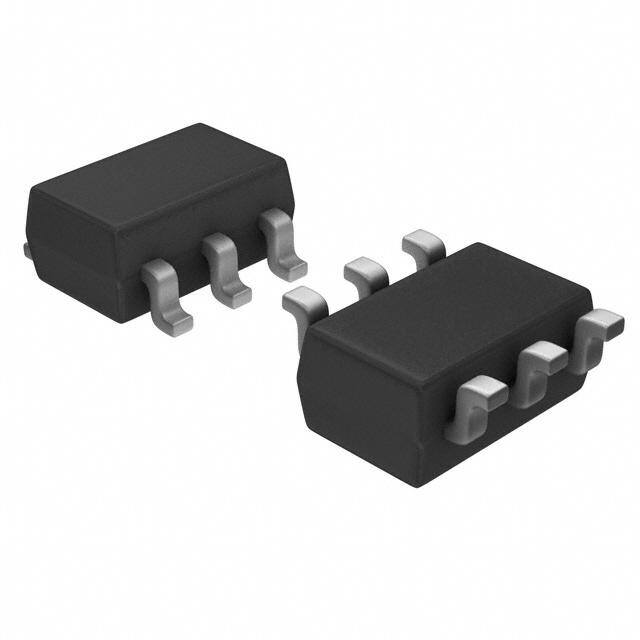
| 描述 | IC MMIC GAAS SW SPDT SOT26 |
| 产品分类 | RF 开关 |
| IIP3 | 55dBm (标准) |
| 品牌 | Hittite Microwave Corporation |
| 数据手册 | 点击此处下载产品Datasheet |
| 产品图片 |  |
| P1dB | 36dBm (标准) IP1dB |
| 产品型号 | HMC544E |
| RF类型 | 通用 |
| rohs | 无铅 / 符合限制有害物质指令(RoHS)规范要求 |
| 产品系列 | - |
| 供应商器件封装 | SOT-26 |
| 其它名称 | 1127-1055-6 |
| 包装 | Digi-Reel® |
| 封装/外壳 | SOT-23-6 |
| 工作温度 | -40°C ~ 85°C |
| 拓扑 | 反射 |
| 插损@频率 | 0.7dB @ 4GHz |
| 标准包装 | 1 |
| 特性 | - |
| 特色产品 | http://www.digikey.cn/product-highlights/zh/new-hmc-series-spdt-switches/53047 |
| 电压-电源 | - |
| 电路 | SPDT |
| 阻抗 | 50 欧姆 |
| 隔离@频率 | 12dB @ 4GHz (标准) |
| 频率 -上 | 4GHz |
| 频率 -下 | DC |
Datasheet
PDF Datasheet 数据手册内容提取
HMC544 544E / v00.0206 GaAs MMIC T/R SWITCH, DC - 4 GHz Typical Applications Features The HMC544 / HMC544E is ideal for: Very Low Insertion Loss: 0.2 dB @ 1.0 GHz • Cellular/PCS/3G Infrastructure High Input P1dB: +39 dBm • Basestations & Repeaters High Input IP3: +55 dBm • WLAN, WiMAX and WiBro Positive Control: 0/+3V to 0/+5V • Microwave and Fixed Wireless Radios Compact SOT26 SMT Package Functional Diagram General Description 10 The HMC544 & HMC544E are low cost SPDT swit- ches in 6-lead SOT26 packages for use in transmit- receive applications which require very low insertion loss at medium power levels. These devices can T M control signals from DC to 4.0 GHz and are especially suited for 450, 900, 1900, 2300, and 2700 MHz S applications with <0.5 dB insertion loss. This GaAs - PHEMT design provides exceptional linearity S performance of +36 dBm 1dB compression point and E +55 dBm third order intercept at +3 volt bias. RF1 H and RF2 are refl ective opens when “Off”. On-chip C circuitry allows positive control operation at very low T I DC current. W S Electrical Specifi cations, T = +25° C, Vctl = 0/+3 Vdc, 50 Ohm System A Parameter Frequency Min. Typ. Max. Units DC - 1.0 GHz 0.25 0.5 dB DC - 2.5 GHz 0.4 0.7 dB Insertion Loss DC - 3.0 GHz 0.5 0.8 dB DC - 4.0 GHz 0.7 1.0 dB DC - 1.0 GHz 18 23 dB DC - 2.5 GHz 10 14 dB Isolation DC - 3.0 GHz 9 13 dB DC - 4.0 GHz 8 12 dB Return Loss DC - 4.0 GHz 32 dB 0/+5V Control 36 39 dBm Input Power for 1 dB Compression 0.3 - 4.0 GHz 0/+3V Control 33 36 dBm Input Third Order Intercept 0.3 - 4.0 GHz 55 dBm (Two-Tone Input Power = +27 dBm Each Tone) Switching Characteristics DC - 4.0 GHz tRISE, tFALL (10/90% RF) 70 ns tON, tOFF (50% CTL to 10/90% RF) 140 ns For price, delivery, and to place orders, please contact Hittite Microwave Corporation: Information furnished by Analog Devices is believed to be accurate and reliable. However, no For price, delivery, and to place orders: Analog Devices, Inc., 10 - 300 rriegshptso nosf ibthiilritdy pisa artsiessu mthea2dt m0bya yAA rnelaspluolhgt faDroe mvRi citeos sua fsoedr. i,tSs p Cuescheif,i ecnaoltrmio fnossr asfnuoyb rjiendcfrt,i nt ogM ecmhAaenn gt0se 1owf8 iptha2otue4tn tnsPo otihcr eoo.t hNneore : 9OPh7noe8n T-ee2: c57h80n1o--33lo23g9y4- 4W37 a0 y0F, a(cid:127)P .xOO:r. d 9Be7or x8o n9-l12in05e6 0,a N-t 3wor3ww7wo3o.adn, aMloAg .0c2o0m6 2-9106 license is granted by implication or otherwise under any patent Oor pradteentr riOghtns -olf iAnneal oag tD ewvicwesw. .hittite.com Trademarks and registered trademarks are the property of their respective owners. Application Support: Phone: 1-800-ANALOG-D
HMC544 / 544E v00.0206 GaAs MMIC T/R SWITCH, DC - 4 GHz Insertion Loss Return Loss 0 0 -10 OSS (dB)-0.5 SS (dB)-20 RRFFC1, RF2 ON L -1 N LO NSERTI-1.5 ++2855CC RETUR-30 I -40C -40 -2 -50 0 0.5 1 1.5 2 2.5 3 3.5 4 4.5 0 0.5 1 1.5 2 2.5 3 3.5 4 4.5 FREQUENCY (GHz) FREQUENCY (GHz) 10 Isolation Between Ports RFC & RF1 / RF2 Isolation Between Ports RF1 & RF2 T 0 0 M -5 -5 S -10 -10 - dB)-15 dB)-15 S N ( N ( E O-20 O-20 ATI ATI H SOL-25 RRFF12 SOL-25 C I-30 I-30 RRFF12 OONN T -35 -35 I W -40 -40 S 0 0.5 1 1.5 2 2.5 3 3.5 4 4.5 0 0.5 1 1.5 2 2.5 3 3.5 4 4.5 FREQUENCY (GHz) FREQUENCY (GHz) Input IP3 vs. Temperature, Vctl = 0/+3V Input IP3 vs. Vctl 65 65 60 60 m) m) B B d 55 d 55 3 ( 3 ( P P T I T I U 50 U 50 +3V P P +5V N N I I +25C 45 +85C 45 -40C 40 40 0 0.5 1 1.5 2 2.5 3 3.5 4 0 0.5 1 1.5 2 2.5 3 3.5 4 FREQUENCY (GHz) FREQUENCY (GHz) For price, delivery, and to place orders, please contact Hittite Microwave Corporation: Information furnished by Analog Devices is believed to be accurate and reliable. However, no For price, delivery, and to place orders: Analog Devices, Inc., responsibility is assume2d 0by AAnlaplohg aDe vRiceosa fodr i,ts Cushe, enolrm fosr afnoy rindfr,in gMemAen t0s 1of8 pa2te4n tsP ohr oothnere : 9O7ne8 T-e2c5h0no-3lo3gy4 W3 a yF, aP.xO:. 9B7ox8 9-120560, N-3or3w7o3od, MA 02062-9106 10 - 301 rights of third parties that may result from its use. Specifications subject to change without notice. No Phone: 781-329-4700 (cid:127) Order online at www.analog.com license is granted by implication or otherwise under any patent Oor pradteentr riOghtns -olf iAnneal oag tD ewvicwesw. .hittite.com Trademarks and registered trademarks are the property of their respective owners. Application Support: Phone: 1-800-ANALOG-D
HMC544 / 544E v00.0206 GaAs MMIC T/R SWITCH, DC - 4.0 GHz Input P1dB vs. Temperature, Vctl = 0/+3V Compression vs. Vctl 45 45 m) 40 B 40 d m) B ( B d PUT P1dB (d 3305 ++-428055CCC P0.1dB & P1 3305 IN UT P0.1dB +3V 25 NP 25 P 0P.11ddBB ++53VV I P1dB +5V 20 20 0 0.5 1 1.5 2 2.5 3 3.5 4 0 0.5 1 1.5 2 2.5 3 3.5 4 10 FREQUENCY (GHz) FREQUENCY (GHz) Truth Table Control Voltages T M Control Input Signal Path State Bias Condition S A B RFC to RF1 RFC to RF2 Low 0 to 0.2 Vdc @ 1 µA Typical Low High On Off +3 Vdc @ 0.5 µA Typical to - High S High Low Off On +5 Vdc @ 2 µA Typical (±0.2 Vdc) E H C T I W S For price, delivery, and to place orders, please contact Hittite Microwave Corporation: Information furnished by Analog Devices is believed to be accurate and reliable. However, no For price, delivery, and to place orders: Analog Devices, Inc., 10 - 302 rriegshptso nosf ibthiilritdy pisa artsiessu mthea2dt m0bya yAA rnelaspluolhgt faDroe mvRi citeos sua fsoedr. i,tSs p Cuescheif,i ecnaoltrmio fnossr asfnuoyb rjiendcfrt,i nt ogM ecmhAaenn gt0se 1owf8 iptha2otue4tn tnsPo otihcr eoo.t hNneore : 9OPh7noe8n T-ee2: c57h80n1o--33lo23g9y4- 4W37 a0 y0F, a(cid:127)P .xOO:r. d 9Be7or x8o n9-l12in05e6 0,a N-t 3wor3ww7wo3o.adn, aMloAg .0c2o0m6 2-9106 license is granted by implication or otherwise under any patent Oor pradteentr riOghtns -olf iAnneal oag tD ewvicwesw. .hittite.com Trademarks and registered trademarks are the property of their respective owners. Application Support: Phone: 1-800-ANALOG-D
HMC544 / 544E v00.0206 GaAs MMIC T/R SWITCH, DC - 4.0 GHz Absolute Maximum Ratings RF Input Power (Vctl = 0/+5V) +39 dBm ELECTROSTATIC SENSITIVE DEVICE Control Voltage Range (A & B) -0.2 to +12 Vdc OBSERVE HANDLING PRECAUTIONS Hot Switch Power Level +39 dBm (Vctl = 0/+5V) Channel Temperature 150 °C Continuous Pdiss (T= 85 °C) 0.465 W (derate 7.14 mW/ °C above 85°C) Thermal Resistance 140 °C/W Storage Temperature -65 to +150 °C Operating Temperature -40 to +85 °C ESD Sensitivity (HBM) Class 1A DC blocks are required at ports RFC, RF1 and RF2. 10 Outline Drawing T M S - S E H C T I W S NOTES: 1. LEADFRAME MATERIAL: COPPER ALLOY 2. DIMENSIONS ARE IN INCHES [MILLIMETERS]. 3. DIMENSION DOES NOT INCLUDE MOLDFLASH OF 0.15mm PER SIDE. 4. DIMENSION DOES NOT INCLUDE MOLDFLASH OF 0.25mm PER SIDE. 5. ALL GROUND LEADS MUST BE SOLDERED TO PCB RF GROUND. Package Information Part Number Package Body Material Lead Finish MSL Rating Package Marking [3] HMC544 Low Stress Injection Molded Plastic Sn/Pb Solder MSL1 [1] H544 XXXX HMC544E RoHS-compliant Low Stress Injection Molded Plastic 100% matte Sn MSL1 [2] 544E XXXX [1] Max peak refl ow temperature of 235 °C [2] Max peak refl ow temperature of 260 °C [3] 4-Digit lot number XXXX For price, delivery, and to place orders, please contact Hittite Microwave Corporation: Information furnished by Analog Devices is believed to be accurate and reliable. However, no For price, delivery, and to place orders: Analog Devices, Inc., responsibility is assume2d 0by AAnlaplohg aDe vRiceosa fodr i,ts Cushe, enolrm fosr afnoy rindfr,in gMemAen t0s 1of8 pa2te4n tsP ohr oothnere : 9O7ne8 T-e2c5h0no-3lo3gy4 W3 a yF, aP.xO:. 9B7ox8 9-120560, N-3or3w7o3od, MA 02062-9106 10 - 303 rights of third parties that may result from its use. Specifications subject to change without notice. No Phone: 781-329-4700 (cid:127) Order online at www.analog.com license is granted by implication or otherwise under any patent Oor pradteentr riOghtns -olf iAnneal oag tD ewvicwesw. .hittite.com Trademarks and registered trademarks are the property of their respective owners. Application Support: Phone: 1-800-ANALOG-D
HMC544 / 544E v00.0206 GaAs MMIC T/R SWITCH, DC - 4.0 GHz Typical Application Circuit 10 T M S Notes: - 1. Set logic gate Vdd = +3V to +5V and use HCT series logic to provide a TTL driver interface. S E 2. Control inputs A/B can be driven directly with CMOS logic (HC) with Vdd of +3V to +5V applied to the CMOS logic gates. H 3. DC Blocking capacitors are required for each RF port as shown. Capacitor value determines lowest frequency of operation. C T I W S Pin Descriptions Pin Number Function Description Interface Schematic These pins are DC coupled and matched to 50 Ohms. 1, 3, 5 RF2, RF1, RFC Blocking capacitors are required. 2 GND This pin must be connected to RF/DC ground. 4 B See truth and control voltage tables. 6 A See truth and control voltage tables. For price, delivery, and to place orders, please contact Hittite Microwave Corporation: Information furnished by Analog Devices is believed to be accurate and reliable. However, no For price, delivery, and to place orders: Analog Devices, Inc., 10 - 304 rriegshptso nosf ibthiilritdy pisa artsiessu mthea2dt m0bya yAA rnelaspluolhgt faDroe mvRi citeos sua fsoedr. i,tSs p Cuescheif,i ecnaoltrmio fnossr asfnuoyb rjiendcfrt,i nt ogM ecmhAaenn gt0se 1owf8 iptha2otue4tn tnsPo otihcr eoo.t hNneore : 9OPh7noe8n T-ee2: c57h80n1o--33lo23g9y4- 4W37 a0 y0F, a(cid:127)P .xOO:r. d 9Be7or x8o n9-l12in05e6 0,a N-t 3wor3ww7wo3o.adn, aMloAg .0c2o0m6 2-9106 license is granted by implication or otherwise under any patent Oor pradteentr riOghtns -olf iAnneal oag tD ewvicwesw. .hittite.com Trademarks and registered trademarks are the property of their respective owners. Application Support: Phone: 1-800-ANALOG-D
HMC544 / 544E v00.0206 GaAs MMIC T/R SWITCH, DC - 4.0 GHz Evaluation Circuit Board 10 T M S - S E H C T I W S List of Materials for Evaluation PCB 101675 [1] The circuit board used in the fi nal application Item Description should be generated with proper RF circuit design J1 - J5 PCB Mount SMA RF Connector techniques. Signal lines at the RF port should J6 - J8 DC Pin have 50 ohm impedance and the package ground C1 - C5 330 pF capacitor, 0402 Pkg. leads should be connected directly to the ground U1 HMC544 / HMC544E SPDT Switch plane similar to that shown above. The evalua- PCB [2] 101659 Evaluation PCB tion circuit board shown above is available from [1] Reference this number when ordering complete evaluation PCB Hittite Microwave Corporation upon request. [2] Circuit Board Material: Rogers 4350 For price, delivery, and to place orders, please contact Hittite Microwave Corporation: Information furnished by Analog Devices is believed to be accurate and reliable. However, no For price, delivery, and to place orders: Analog Devices, Inc., responsibility is assume2d 0by AAnlaplohg aDe vRiceosa fodr i,ts Cushe, enolrm fosr afnoy rindfr,in gMemAen t0s 1of8 pa2te4n tsP ohr oothnere : 9O7ne8 T-e2c5h0no-3lo3gy4 W3 a yF, aP.xO:. 9B7ox8 9-120560, N-3or3w7o3od, MA 02062-9106 10 - 305 rights of third parties that may result from its use. Specifications subject to change without notice. No Phone: 781-329-4700 (cid:127) Order online at www.analog.com license is granted by implication or otherwise under any patent Oor pradteentr riOghtns -olf iAnneal oag tD ewvicwesw. .hittite.com Trademarks and registered trademarks are the property of their respective owners. Application Support: Phone: 1-800-ANALOG-D