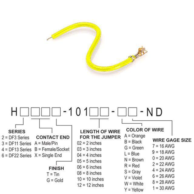
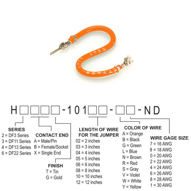
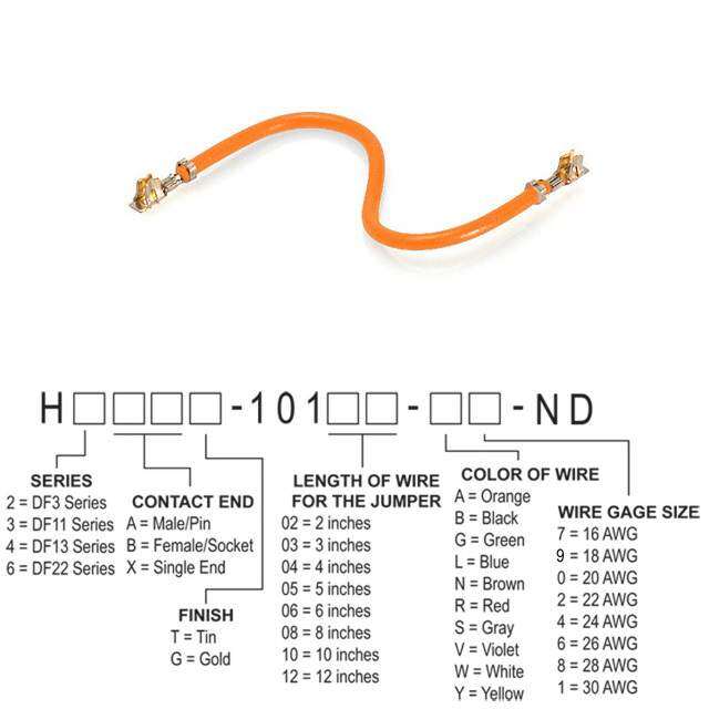
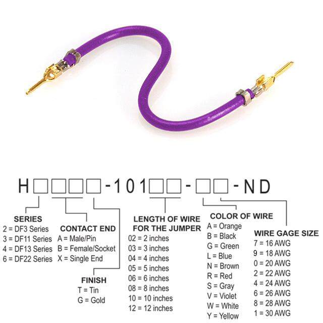
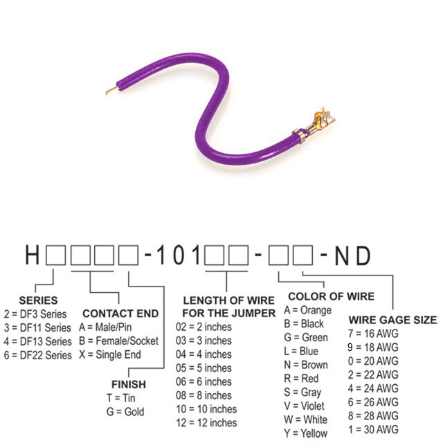
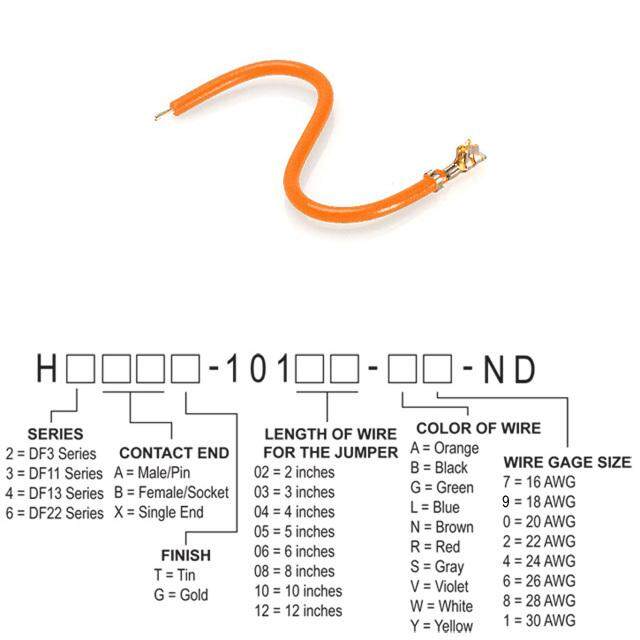
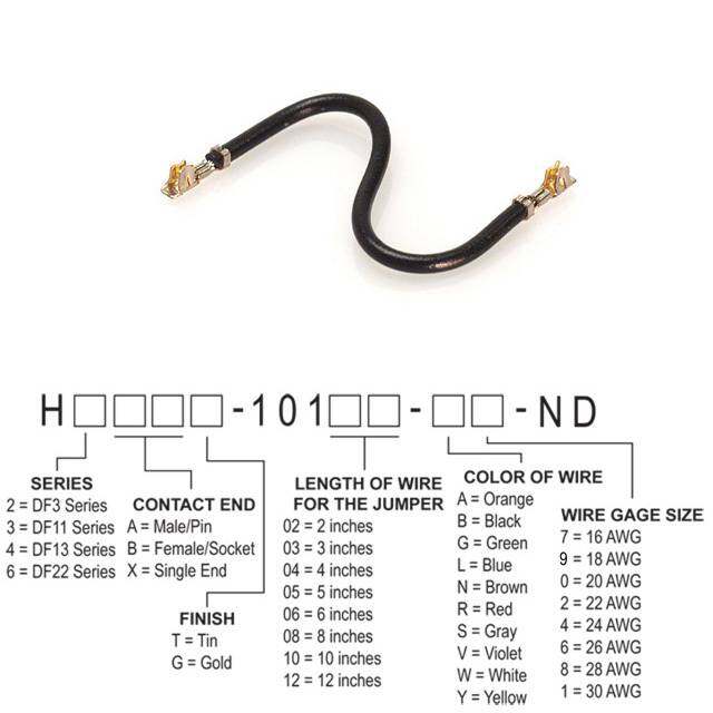
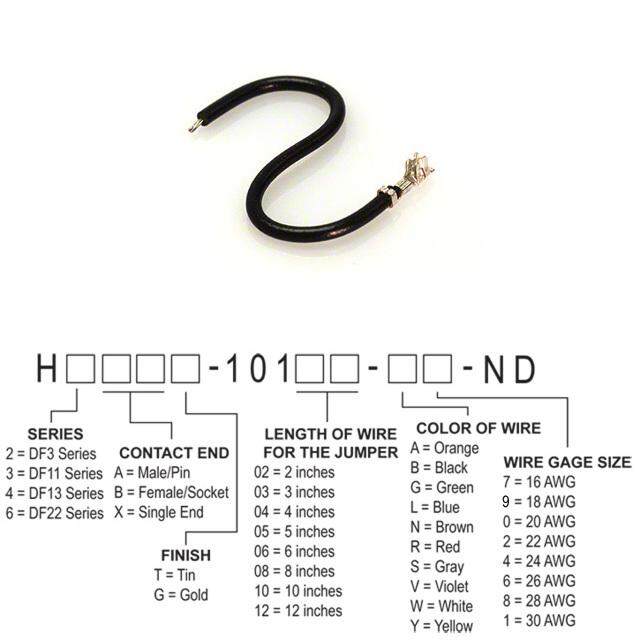
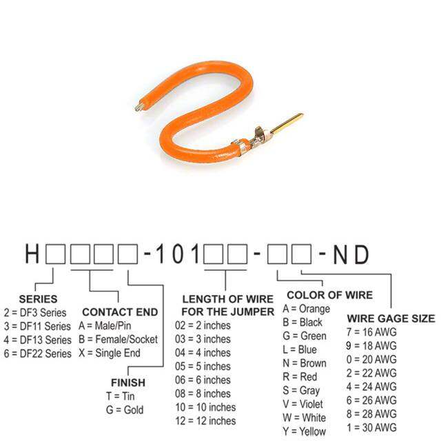
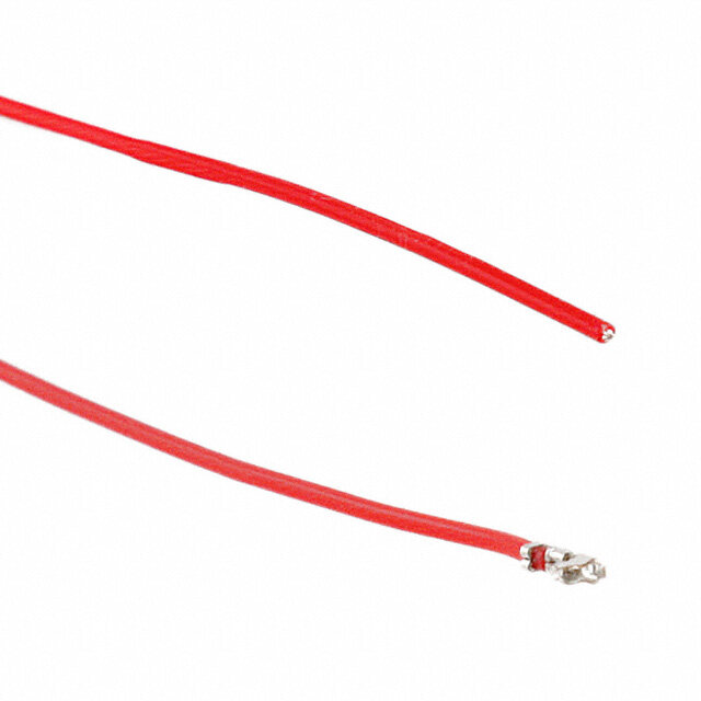
- 型号: H3BXG-10106-A4
- 制造商: Hirose Electric
- 库位|库存: xxxx|xxxx
- 要求:
| 数量阶梯 | 香港交货 | 国内含税 |
| +xxxx | $xxxx | ¥xxxx |
查看当月历史价格
查看今年历史价格
H3BXG-10106-A4产品简介:
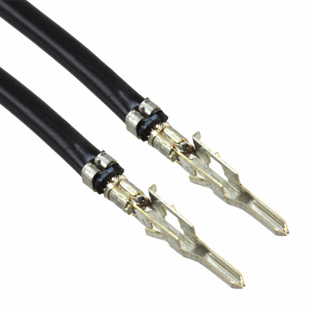
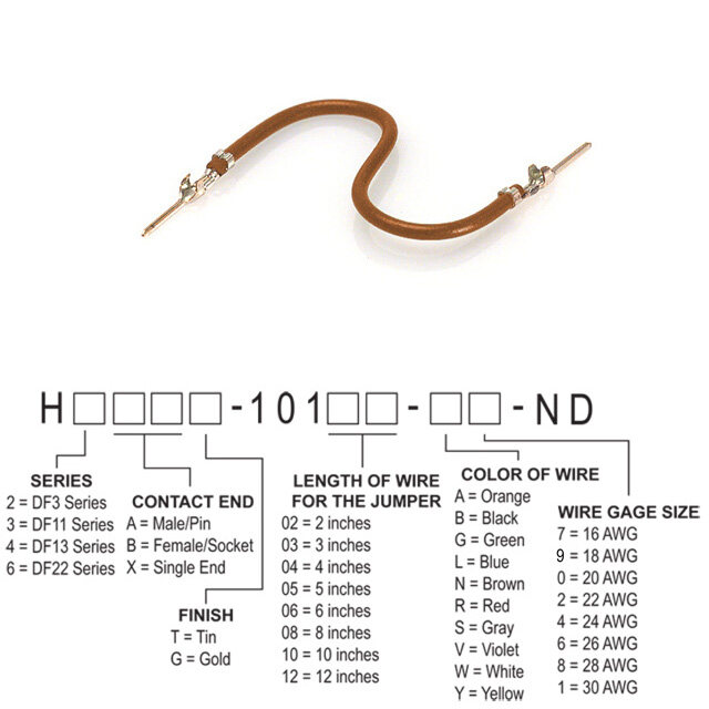
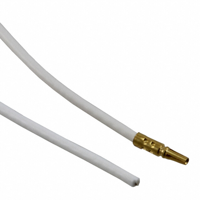
ICGOO电子元器件商城为您提供H3BXG-10106-A4由Hirose Electric设计生产,在icgoo商城现货销售,并且可以通过原厂、代理商等渠道进行代购。 H3BXG-10106-A4价格参考。Hirose ElectricH3BXG-10106-A4封装/规格:跳线,预压接引线, 橙色 24 AWG Jumper Lead 插口至线缆(圆形) 金 6.00"(152.40mm)。您可以下载H3BXG-10106-A4参考资料、Datasheet数据手册功能说明书,资料中有H3BXG-10106-A4 详细功能的应用电路图电压和使用方法及教程。
| 参数 | 数值 |
| 产品目录 | |
| 描述 | JUMPER-H1505TR/A2015A/X 6" |
| 产品分类 | 跳线,预压接 |
| 品牌 | Hirose Electric Co Ltd |
| 数据手册 | |
| 产品图片 |
|
| 产品型号 | H3BXG-10106-A4 |
| rohs | 无铅 / 符合限制有害物质指令(RoHS)规范要求 |
| 产品系列 | DF11 |
| 产品培训模块 | http://www.digikey.cn/PTM/IndividualPTM.page?site=cn&lang=zhs&ptm=24779 |
| 导体数 | 1 |
| 排数 | 1 |
| 接触端 | 插口至线缆(圆形) |
| 标准包装 | 10 |
| 线规 | 24 AWG |
| 触头镀层 | 金 |
| 触头镀层厚度 | - |
| 长度 | 6.0"(152.4mm) |
| 颜色 | 橙 |


- 商务部:美国ITC正式对集成电路等产品启动337调查
- 曝三星4nm工艺存在良率问题 高通将骁龙8 Gen1或转产台积电
- 太阳诱电将投资9.5亿元在常州建新厂生产MLCC 预计2023年完工
- 英特尔发布欧洲新工厂建设计划 深化IDM 2.0 战略
- 台积电先进制程称霸业界 有大客户加持明年业绩稳了
- 达到5530亿美元!SIA预计今年全球半导体销售额将创下新高
- 英特尔拟将自动驾驶子公司Mobileye上市 估值或超500亿美元
- 三星加码芯片和SET,合并消费电子和移动部门,撤换高东真等 CEO
- 三星电子宣布重大人事变动 还合并消费电子和移动部门
- 海关总署:前11个月进口集成电路产品价值2.52万亿元 增长14.8%



PDF Datasheet 数据手册内容提取
DF11 Series 2.0mm Pitch, Double-Row Connector (UL/CSA Complaint) Oct. 2020
DF11 Series/2.0mm Pitch, Double-Row Connector (UL/CSA Complaint) Features 1. Space-saving on Board Double row contact arrangement with 2mm pitch has been condensed within a 5mm width. Rib to Prevent Double the number of signals can be secured in Mis-insertion Friction Lock the same space as a conventional 2mm single- row connector. Rib to prevent contact insertion between dissimilar contacts 5mm 4 Wall Box Style 2. Wide Varieties There are two types of connection methods : insulation displacement and crimping. Variations are available in cable-to-board, in-line, and board-to-board to expand PCB design freedom. Additionally, both gold and tin plating can be selected based on the application and SMT compatible products are also available. 3. Wide Applicable Wire Range The double 2mm pitch rows are compact while enabling an applicable wire range of 22 to 30 AWG. 4. The IDC Type enables reduced assembly time Since the DF11 insulation displacemention allows double rows IDC with a single part, harnessing can be completed by machine connection alone. Applications Business equipment such as copy machines, printers and so on. 2
DF11 Series/2.0mm Pitch, Double-Row Connector (UL/CSA Complaint) Product Specifications Ratings Crimping Insulation Displacement 22 to 26 AWG 28 AWG 30 AWG 26 AWG Rated Current (Note 1) 2A 1A 0.5A 1A Rated Voltage 250V AC 100V AC Operating Temperature Range -30 to +85℃ (Note 2) Operating Humidity Range 40 to 80% (Note 3) Storage Temperature Range -10 to +60℃ (Note 4) Storage Humidity Range 40 to 70% (Note 4) UL, CSA Safety Standard Approved Specification ■UL, CSA Safety Standard File No. Wire Size 22 AWG 24 to 28 AWG 30 AWG UL : E52653 Rated Current 2A 1A 0.5A CSA : LR95109 Rated Voltage 30V AC Item Specification Condition Insulation Resistance 1000MΩ Min. 500V DC Withstanding Voltage No flashover or insulation breakdown. 650V AC for 1 min. Contact Resistance 30mΩ Max. 100mA Single Insertion/ 0.3N (30gf) Min. Measured by the square steel pin at 0.5±0.002mm Extraction Force 4.4N (450gf) Max. Frequency : 10 to 55Hz, single amplitude of 0.75mm, Vibration No electrical discontinuity of 1μs or more 2 hours in each of the 3 directions. Humidity Contact Resistance : 30mΩ Max. 96 hours at temperature of 40±2℃ (Steady State) Insulation Resistance : 500MΩ Min. and humidity of 90 to 95% Contact Resistance : 30mΩ Max. (-55℃:30 minutes →5 to 35℃:10 minutes Temperature Cycle Insulation Resistance : 1000MΩ Min. →85℃:30 minutes →5 to 35℃:10 minutes) 5 cycles Tin Plated : 30 cycles, Mating Durability Contact Resistance : 30mΩ Max. Gold Plated : 50 cycles Flow : Manual soldering : Through Hole 260℃ for 10 seconds 300℃ for 2 seconds Resistance to No deformation of Soldering Heat components affecting performance. Reflow : At the Manual soldering : SMT recommended 300℃ for 3 seconds temperature profile Note 1 : This is the maximum current rating while all pins are powered or used as all power lines. When isolating power lines into multiple circuits, current ratings may go above the stated current ratings. Please consult Hirose for details before doing this. Current rating of header is 2A. Note 2 : Includes the temperature rise due to current flow. Note 3 : The connector should be completely dry. (no condensation) Note 4 : The term "storage" refers to the long-term storage condition of unused products before PCB mounting. The operating temperature and humidity ranges apply while the connector is in a non-energized state, while in transport or after PCB mounting. 3
DF11 Series/2.0mm Pitch, Double-Row Connector (UL/CSA Complaint) Material / Finish Product Type Part MateriaI Finish Remarks Crimping Socket Insulator Polyamide Black UL94V-0 Crimping Contact for Socket Contact Phosphor Copper Tin Plated or Gold Plated - Insulator Polyamide Black UL94V-0 IDC Socket Contact Phosphor Copper Tin Plated - Insulator Polyamide Black UL94V-0 Receptacle Contact Phosphor Copper Tin Plated or Gold Plated - Insulator Polyamide Black UL94V-0 Pin Header Contact Brass Tin Plated or Gold Plated - Insulator Polyamide Beige UL94V-0 SMT Header Contact Brass Tin Plated or Gold Plated - Retention Tab Brass Tin Plated - In-line Plug Insulator Polyamide Black UL94V-0 In-line Plug Crimping Contact Contact Phosphor Copper Tin Plated or Gold Plated - Insulator Polyamide Black UL94V-0 In-line Adaptor Contact Brass Tin Plated - Product Number Structure Refer to the chart below when determining the product specifications from the product number. Please select from the product numbers listed in this catalog when placing orders. ● Connector DF11 - # DS - 2 C ❶ ❷ ❸ ❹ ❺ ❶ Series Name DF11 ❺ Connection Form/ C : Crimping Socket ❷ No. of Pos. 4 to 32 Contact Style R26 : IDC Socket for 26 AWG DSA : Straight Through Hole DS : Double Row Socket DS : Right Angle Through Hole ❸ Connector Type DP : Double Row Pin Header V : Straight SMT DEP : Double Row In-line Plug A : Adaptor ❹ Contact Pitch 2mm ● Contact DF11 - EP 2428 PCF A ❶ ❷ ❸ ❹ ❶ Contact Type EP : For In-line Plug ❹ Plating Type Blank:Tin Plated A :Gold Plated ❷ Applicable Wire 22 : 22 AWG Size 2428 : 24 to 28 AWG 30 : 30 AWG ❸ Contact Type/ SCF : Socket Contact, Embossed Tape Packaging Type SC : Socket Contact, Bag PCF : Plug Contact, Embossed Tape PC : Plug Contact, Bag 4
DF11 Series/2.0mm Pitch, Double-Row Connector (UL/CSA Complaint) IDC Socket A No. 2 B 5 P=2.0 1. 0 6.52. 0 3. No. 1 No. of Pos. Indicator Contact No.1 Marking Note 1 CAV No. Marking Shown Assembled with Cable 23 2 1 A 9. Note 2 Note 1 : Port 1-pcs indicates odd numbered rows, and port 2-pcs indicate even numbered rows. Note 2 : Use the following DIP type headers: · Straight angle type : DF11-#DP-2DSA(08) · Angle type : DF11-#DP-2DS(24) Unit : mm Part No. HRS No. No. of Pos. A B Purchase Unit DF11-4DS-2R26(05) CL0543-0652-0-05 4 6.0 2.0 DF11-6DS-2R26(05) CL0543-0653-3-05 6 8.0 4.0 DF11-8DS-2R26(05) CL0543-0654-6-05 8 10.0 6.0 DF11-10DS-2R26(05) CL0543-0655-9-05 10 12.0 8.0 DF11-12DS-2R26(05) CL0543-0656-1-05 12 14.0 10.0 DF11-14DS-2R26(05) CL0543-0657-4-05 14 16.0 12.0 DF11-16DS-2R26(05) CL0543-0658-7-05 16 18.0 14.0 100pcs DF11-18DS-2R26(05) CL0543-0659-0-05 18 20.0 16.0 per bag DF11-20DS-2R26(05) CL0543-0660-9-05 20 22.0 18.0 DF11-22DS-2R26(05) CL0543-0661-1-05 22 24.0 20.0 DF11-24DS-2R26(05) CL0543-0662-4-05 24 26.0 22.0 DF11-26DS-2R26(05) CL0543-0663-7-05 26 28.0 24.0 DF11-28DS-2R26(05) CL0543-0664-0-05 28 30.0 26.0 DF11-30DS-2R26(05) CL0543-0665-2-05 30 32.0 28.0 DF11-32DS-2R26(05) CL0543-0666-5-05 32 34.0 30.0 [Specific No.] (05) : Tin Plated ■ Applicable Cable Part No. Applicable Cable Jacket Diameter DF11-#DS-2R26 UL1061 26 AWG (7/0.16mm) φ0.9 to 1.05mm ■ DF11-#DS-2R IDC Machine Type Part No. Connection Type Remarks SA700/DF11 Used for DF11 only, Desktop IDC Machine Desktop machine for small lot CL0903-0013-5-00 No restricted condition 5
DF11 Series/2.0mm Pitch, Double-Row Connector (UL/CSA Complaint) Crimping Socket A B No.2 P=2.0 5.02.0 No.1 Shown Assembled with Cable 3 7. Polarity Mark CAV No. Marking Unit : mm Part No. HRS No. No. of Pos. A B Purchase Unit DF11-4DS-2C CL0543-0568-6-00 4 6.0 2.0 DF11-6DS-2C CL0543-0502-8-00 6 8.0 4.0 DF11-8DS-2C CL0543-0503-0-00 8 10.0 6.0 DF11-10DS-2C CL0543-0504-3-00 10 12.0 8.0 DF11-12DS-2C CL0543-0505-6-00 12 14.0 10.0 DF11-14DS-2C CL0543-0506-9-00 14 16.0 12.0 DF11-16DS-2C CL0543-0507-1-00 16 18.0 14.0 100pcs DF11-18DS-2C CL0543-0508-4-00 18 20.0 16.0 per bag DF11-20DS-2C CL0543-0509-7-00 20 22.0 18.0 DF11-22DS-2C CL0543-0510-6-00 22 24.0 20.0 DF11-24DS-2C CL0543-0511-9-00 24 26.0 22.0 DF11-26DS-2C CL0543-0512-1-00 26 28.0 24.0 DF11-28DS-2C CL0543-0513-4-00 28 30.0 26.0 DF11-30DS-2C CL0543-0514-7-00 30 32.0 28.0 DF11-32DS-2C CL0543-0515-0-00 32 34.0 30.0 6
DF11 Series/2.0mm Pitch, Double-Row Connector (UL/CSA Complaint) Receptacle (Through Hole) A B No. 2 P=2.0 00 5.2. No. 1 Polarity Mark ● Board Through-hole Diameter : φ0.8+0.1 0 ● Diameter of Board Hole for Kink Pin 2 Securing : φ0.8+0.05 6. 0 0 3. 0.6 0.2 Unit : mm Part No. HRS No. No. of Pos. A B Purchase Unit DF11-6DS-2DSA(##) CL0543-0553-9-## 6 8.0 4.0 DF11-8DS-2DSA(##) CL0543-0554-1-## 8 10.0 6.0 DF11-10DS-2DSA(##) CL0543-0555-4-## 10 12.0 8.0 DF11-12DS-2DSA(##) CL0543-0556-7-## 12 14.0 10.0 DF11-14DS-2DSA(##) CL0543-0557-0-## 14 16.0 12.0 DF11-16DS-2DSA(##) CL0543-0558-2-## 16 18.0 14.0 DF11-18DS-2DSA(##) CL0543-0559-5-## 18 20.0 16.0 100pcs DF11-20DS-2DSA(##) CL0543-0560-4-## 20 22.0 18.0 per bag DF11-22DS-2DSA(##) CL0543-0561-7-## 22 24.0 20.0 DF11-24DS-2DSA(##) CL0543-0562-0-## 24 26.0 22.0 DF11-26DS-2DSA(##) CL0543-0563-2-## 26 28.0 24.0 DF11-28DS-2DSA(##) CL0543-0564-5-## 28 30.0 26.0 DF11-30DS-2DSA(##) CL0543-0565-8-## 30 32.0 28.0 DF11-32DS-2DSA(##) CL0543-0566-0-## 32 34.0 30.0 [Specific No.] -##,(##) (05) : Tin Plated (06) : Gold Plated 7
DF11 Series/2.0mm Pitch, Double-Row Connector (UL/CSA Complaint) Receptacle (SMT) No.2 A CAV No. Marking P=2.0 0.7 5 1. 00 5.2. 5 1. No.1 1.5 B 1.5 5 59 5.94. Polarity Mark ■ PCB Mounting Pattern A±0.1 1 P=2.0±0.05 1.1±0.1 0. ± 0 2. 1 1 0. 0. ± ± 1 8 5. 2. 1 0. ± 0 2. 2.0±0.1 C±0.1 2.0±0.1 Note : If the shaded area has a pattern and is not treated with resist it may touch the connector contact. Unit : mm Part No. HRS No. No. of Pos. A B C Purchase Unit DF11CZ-4DS-2V(##) CL0543-2063-0-## 4 2.0 8.5 8.7 DF11CZ-6DS-2V(##) CL0543-2064-3-## 6 4.0 10.5 10.7 DF11CZ-8DS-2V(##) CL0543-2065-6-## 8 6.0 12.5 12.7 DF11CZ-10DS-2V(##) CL0543-2066-9-## 10 8.0 14.5 14.7 DF11CZ-12DS-2V(##) CL0543-2067-1-## 12 10.0 16.5 16.7 DF11CZ-14DS-2V(##) CL0543-2068-4-## 14 12.0 18.5 18.7 DF11CZ-16DS-2V(##) CL0543-2069-7-## 16 14.0 20.5 20.7 500pcs DF11CZ-18DS-2V(##) CL0543-2070-6-## 18 16.0 22.5 22.7 per reel DF11CZ-20DS-2V(##) CL0543-2071-9-## 20 18.0 24.5 24.7 DF11CZ-22DS-2V(##) CL0543-2072-1-## 22 20.0 26.5 26.7 DF11CZ-24DS-2V(##) CL0543-2073-4-## 24 22.0 28.5 28.7 DF11CZ-26DS-2V(##) CL0543-2074-7-## 26 24.0 30.5 30.7 DF11CZ-28DS-2V(##) CL0543-2075-0-## 28 26.0 32.5 32.7 DF11CZ-30DS-2V(##) CL0543-2076-2-## 30 28.0 34.5 34.7 DF11CZ-40DS-2V(##) CL0543-0584-2-## 40 38.0 44.5 44.7 [Specific No.] –##, (##) (22) : Tin Plated Embossed Tape Packaging (with Vacuum Pick-up Cap) (52) : Gold Plated Embossed Tape Packaging (with Vacuum Pick-up Cap) Note 1 : The 40pos. connector can only be combined with SMT products. Note 2 : Embossed packaging products have the reel wrapped in polyethylene and include a desiccant. 8
DF11 Series/2.0mm Pitch, Double-Row Connector (UL/CSA Complaint) Straight Pin Header A B P=2.0 No.2 00 5.2. No.1 ● Board Through-hole Diameter : φ0.8+0.1 0 Polarity Mark 6.6 3.05 3.0 0 6 3. 1. □0.5 Unit : mm Purchase Purchase Purchase No. of Part No. HRS No. A B Unit Unit Unit Pos. (##) : (01) (##) : (08) (##) : (24) 81pcs DF11-4DP-2DSA(##) CL0543-0517-5-## 4 6.0 2.0 per tube 61pcs DF11-6DP-2DSA(##) CL0543-0518-8-## 6 8.0 4.0 per tube 49pcs DF11-8DP-2DSA(##) CL0543-0519-0-## 8 10.0 6.0 per tube 40pcs DF11-10DP-2DSA(##) CL0543-0520-0-## 10 12.0 8.0 per tube 34pcs DF11-12DP-2DSA(##) CL0543-0521-2-## 12 14.0 10.0 per tube 30pc DF11-14DP-2DSA(##) CL0543-0522-5-## 14 16.0 12.0 per tube 27pcs DF11-16DP-2DSA(##) CL0543-0523-8-## 16 18.0 14.0 per tube 100pcs 100pcs 24pcs DF11-18DP-2DSA(##) CL0543-0524-0-## 18 20.0 16.0 per bag per bag per tube 22pcs DF11-20DP-2DSA(##) CL0543-0525-3-## 20 22.0 18.0 per tube 20pcs DF11-22DP-2DSA(##) CL0543-0526-6-## 22 24.0 20.0 per tube 18pcs DF11-24DP-2DSA(##) CL0543-0527-9-## 24 26.0 22.0 per tube 17pcs DF11-26DP-2DSA(##) CL0543-0528-1-## 26 28.0 24.0 per tube 16pcs DF11-28DP-2DSA(##) CL0543-0529-4-## 28 30.0 26.0 per tube 15pcs DF11-30DP-2DSA(##) CL0543-0530-3-## 30 32.0 28.0 per tube 14pcs DF11-32DP-2DSA(##) CL0543-0531-6-## 32 34.0 30.0 per tube [Specific No.] -##,(##) (01) : Gold Plated (08) : Tin Plated (24) : Tin Plated 9
DF11 Series/2.0mm Pitch, Double-Row Connector (UL/CSA Complaint) Right Angle Pin Header □0.5 0 No.2 3. 00 5.2. P=2.0 No.1 B A ● Board Through-hole Diameter : φ0.8+0.1 0 Polarity Mark 0.06.453.05 3.0 7.7 1 5 4 1. 0 2. Unit : mm Part No. HRS No. No. of Pos. A B Purchase Unit DF11-4DP-2DS(##) CL0543-0533-1-## 4 6.0 2.0 81pcs per tube DF11-6DP-2DS(##) CL0543-0534-4-## 6 8.0 4.0 61pcs per tube DF11-8DP-2DS(##) CL0543-0535-7-## 8 10.0 6.0 48pcs per tube DF11-10DP-2DS(##) CL0543-0536-0-## 10 12.0 8.0 40pcs per tube DF11-12DP-2DS(##) CL0543-0537-2-## 12 14.0 10.0 34pcs per tube DF11-14DP-2DS(##) CL0543-0538-5-## 14 16.0 12.0 30pcs per tube DF11-16DP-2DS(##) CL0543-0539-8-## 16 18.0 14.0 27pcs per tube DF11-18DP-2DS(##) CL0543-0540-7-## 18 20.0 16.0 24pcs per tube DF11-20DP-2DS(##) CL0543-0541-0-## 20 22.0 18.0 22pcs per tube DF11-22DP-2DS(##) CL0543-0542-2-## 22 24.0 20.0 20pcs per tube DF11-24DP-2DS(##) CL0543-0543-5-## 24 26.0 22.0 18pcs per tube DF11-26DP-2DS(##) CL0543-0544-8-## 26 28.0 24.0 17pcs per tube DF11-28DP-2DS(##) CL0543-0545-0-## 28 30.0 26.0 16pcs per tube DF11-30DP-2DS(##) CL0543-0546-3-## 30 32.0 28.0 15pcs per tube DF11-32DP-2DS(##) CL0543-0547-6-## 32 34.0 30.0 14pcs per tube [Specific No.] -##,(##) (24) : Tin Plated (52) : Gold Plated 10
DF11 Series/2.0mm Pitch, Double-Row Connector (UL/CSA Complaint) Straight Pin Header (SMT) A P=2.0 A 0.65 P=2 0.65 NNoo..22 1.5 A 2.0 6.2 ø0.5 2.0 NNoo..11 1.5 1.5 B 1.5 5 2.27.2 ■ PCB Mounting Pattern A±0.1 1 0. P=2.0±0.05 1.1±0.1 ± 0 2. 11 0.0. ±± 38 6.2. 1 0. ± 0 2.2.0±0.1 C±0.1 2.0±0.1 Note : If the shaded area has a pattern and is not treated with resist it may touch the connector contact. 11
DF11 Series/2.0mm Pitch, Double-Row Connector (UL/CSA Complaint) Tin Plated Gold Plated No. of Purchase A B C Part No. HRS No. Part No. HRS No. Pos. Unit DF11CZ-4DP-2V(27) CL0543-2047-4-27 DF11C-4DP-2V(57) CL0543-0682-1-57 4 2.0 8.5 8.7 DF11CZ-6DP-2V(27) CL0543-2048-7-27 DF11C-6DP-2V(57) CL0543-0683-4-57 6 4.0 10.5 10.7 DF11CZ-8DP-2V(27) CL0543-2049-0-27 DF11C-8DP-2V(57) CL0543-0684-7-57 8 6.0 12.5 12.7 DF11CZ-10DP-2V(27) CL0543-2050-9-27 DF11C-10DP-2V(57) CL0543-0685-0-57 10 8.0 14.5 14.7 DF11CZ-12DP-2V(27) CL0543-2051-1-27 DF11C-12DP-2V(57) CL0543-0686-2-57 12 10.0 16.5 16.7 DF11CZ-14DP-2V(27) CL0543-2052-4-27 DF11C-14DP-2V(57) CL0543-0687-5-57 14 12.0 18.5 18.7 DF11CZ-16DP-2V(27) CL0543-2053-7-27 DF11C-16DP-2V(57) CL0543-0688-8-57 16 14.0 20.5 20.7 DF11CZ-18DP-2V(27) CL0543-2054-0-27 DF11C-18DP-2V(57) CL0543-0689-0-57 18 16.0 22.5 22.7 500pcs DF11CZ-20DP-2V(27) CL0543-2055-2-27 DF11C-20DP-2V(57) CL0543-0690-0-57 20 18.0 24.5 24.7 per reel DF11CZ-22DP-2V(27) CL0543-2056-5-27 DF11C-22DP-2V(57) CL0543-0691-2-57 22 20.0 26.5 26.7 DF11CZ-24DP-2V(27) CL0543-2057-8-27 DF11C-24DP-2V(57) CL0543-0692-5-57 24 22.0 28.5 28.7 DF11CZ-26DP-2V(27) CL0543-2058-0-27 DF11C-26DP-2V(57) CL0543-0693-8-57 26 24.0 30.5 30.7 DF11CZ-28DP-2V(27) CL0543-2059-3-27 DF11C-28DP-2V(57) CL0543-0694-0-57 28 26.0 32.5 32.7 DF11CZ-30DP-2V(27) CL0543-2060-2-27 DF11C-30DP-2V(57) CL0543-0695-3-57 30 28.0 34.5 34.7 DF11CZ-32DP-2V(27) CL0543-2061-5-27 DF11C-32DP-2V(57) CL0543-0696-6-57 32 30.0 36.5 36.7 DF11CZ-40DP-2V(27) CL0543-2062-8-27 DF11C-40DP-2V(57) CL0543-0697-9-57 40 38.0 44.5 44.7 [Specific No.] -##,(##) (27) : Tin Plated Embossed Tape Packaging (with Vacuum Pick-up Cap) (57) : Gold Plated Embossed Tape Packaging (with Vacuum Pick-up Cap) Note 1 : The 40pos. connector can only be combined with SMT products. Note 2 : Embossed packaging products have the reel wrapped in polyethylene and include a desiccant. Note 3 : There may be blisters on the mold surfaces excluding the mating face during mounting. However this does not affect the product performance. 12
DF11 Series/2.0mm Pitch, Double-Row Connector (UL/CSA Complaint) In-line Plug A B C D 0.9 P=2.0 No.2 6.02.0 No.1 Shown Assembled with Cable 0 5. 0 3. 1 A 1 8 1. CAV No. Marking Polarity Mark ■ In-line Plug Panel Cutouts E+ 00.1 F+ 00.1 2.5+ 00.1 +0.17.3 0 +0.16.3 0 +0.13.9 0 Pパaネnルel Note 1 Note 1 : Please use the non-radius side for the panel hooking area. Note 2 : Applicable panel thickness is 1.6 to 1.0mm (Slight misalignment may occur for the panel thicknesses excluding 1.6 and 1.2mm.) Unit : mm Part No. HRS No. No. of Pos. A B C D E F Purchase Unit DF11-4DEP-2C CL0543-0619-5-00 4 11.0 9.2 6.0 2.0 9.4 6.3 DF11-6DEP-2C CL0543-0620-4-00 6 13.0 11.2 8.0 4.0 11.4 8.3 DF11-8DEP-2C CL0543-0621-7-00 8 15.0 13.2 10.0 6.0 13.4 10.3 DF11-10DEP-2C CL0543-0622-0-00 10 17.0 15.2 12.0 8.0 15.4 12.3 DF11-12DEP-2C CL0543-0623-2-00 12 19.0 17.2 14.0 10.0 17.4 14.3 DF11-14DEP-2C CL0543-0624-5-00 14 21.0 19.2 16.0 12.0 19.4 16.3 DF11-16DEP-2C CL0543-0625-8-00 16 23.0 21.2 18.0 14.0 21.4 18.3 100pcs DF11-18DEP-2C CL0543-0626-0-00 18 25.0 23.2 20.0 16.0 23.4 20.3 per bag DF11-20DEP-2C CL0543-0627-3-00 20 27.0 25.2 22.0 18.0 25.4 22.3 DF11-22DEP-2C CL0543-0628-6-00 22 29.0 27.2 24.0 20.0 27.4 24.3 DF11-24DEP-2C CL0543-0629-9-00 24 31.0 29.2 26.0 22.0 29.4 26.3 DF11-26DEP-2C CL0543-0630-8-00 26 33.0 31.2 28.0 24.0 31.4 28.3 DF11-28DEP-2C CL0543-0631-0-00 28 35.0 33.2 30.0 26.0 33.4 30.3 DF11-30DEP-2C CL0543-0632-3-00 30 37.0 35.2 32.0 28.0 35.4 32.3 DF11-32DEP-2C CL0543-0633-6-00 32 39.0 37.2 34.0 30.0 37.4 34.3 13
DF11 Series/2.0mm Pitch, Double-Row Connector (UL/CSA Complaint) In-line Adaptor A B C D 0.9 P=2.0 2.0 No.2 00 6.2. CAV No.表示 □0.5 No.2 極性マーク 0 5. 12.02.0 0 5. ↑ (注)こちら側の挿抜力は高くしてあります。 No.2 □0.5 No.1 ■ In-line Adaptor Panel Cutouts E+ 00.1 F+ 00.1 2.5+ 00.1 +0.17.3 0 +0.16.3 0 +0.13.9 0 パPaネnルel N注o1te 1 Note 1 : Please use the non-radius surface in the panel hooking area. Note 2 : Applicable panel thickness is 1.6 to 1.0mm (Slight misalignment may occur for the panel thicknesses excluding 1.6 and 1.2mm.) Unit : mm Part No. HRS No. No. of Pos. A B C D E F Purchase Unit DF11-4DEP-2A CL0543-0698-1-00 4 11.0 9.2 6.0 2.0 9.4 6.3 DF11-6DEP-2A CL0543-0699-4-00 6 13.0 11.2 8.0 4.0 11.4 8.3 DF11-8DEP-2A CL0543-0700-1-00 8 15.0 13.2 10.0 6.0 13.4 10.3 DF11-10DEP-2A CL0543-0701-4-00 10 17.0 15.2 12.0 8.0 15.4 12.3 DF11-12DEP-2A CL0543-0702-7-00 12 19.0 17.2 14.0 10.0 17.4 14.3 DF11-14DEP-2A CL0543-0703-0-00 14 21.0 19.2 16.0 12.0 19.4 16.3 DF11-16DEP-2A CL0543-0704-2-00 16 23.0 21.2 18.0 14.0 21.4 18.3 100pcs DF11-18DEP-2A CL0543-0705-5-00 18 25.0 23.2 20.0 16.0 23.4 20.3 per bag DF11-20DEP-2A CL0543-0706-8-00 20 27.0 25.2 22.0 18.0 25.4 22.3 DF11-22DEP-2A CL0543-0707-0-00 22 29.0 27.2 24.0 20.0 27.4 24.3 DF11-24DEP-2A CL0543-0708-3-00 24 31.0 29.2 26.0 22.0 29.4 26.3 DF11-26DEP-2A CL0543-0709-6-00 26 33.0 31.2 28.0 24.0 31.4 28.3 DF11-28DEP-2A CL0543-0710-5-00 28 35.0 33.2 30.0 26.0 33.4 30.3 DF11-30DEP-2A CL0543-0711-8-00 30 37.0 35.2 32.0 28.0 35.4 32.3 DF11-32DEP-2A CL0543-0712-0-00 32 39.0 37.2 34.0 30.0 37.4 34.3 14
DF11 Series/2.0mm Pitch, Double-Row Connector (UL/CSA Complaint) Crimping Contact for Socket (Header Area) 1.35 1.85 1 3. 0 2 1. 6. 2 1. 9.9 70.8 7 0. 0. 5 01. 3. ◆ Reel Contact (Applicable Tool : Applicator) Applicable Wire (Tin Plated Annealed Copper Wire)(Note 2) Purchase Part No. HRS No. Finish Unit UL Wire Standed Wire Calculated Jacket Size Conductor Cross-section Outer Dia. 1.2 to DF11-22SCF CL0543-0601-0-00 Tin Plated 1061 22 AWG 17 / 0.16mm 0.342mm2 1.45mm 1.2 to DF11-22SCFA(04) CL0543-0603-5-04 Gold Plated 1061 22 AWG 17 / 0.16mm 0.342mm2 1.45mm 24 AWG 11 / 0.16mm 0.221mm2 1061, 0.9 to DF11-2428SCF CL0543-0500-2-00 Tin Plated 26 AWG 7 / 0.16mm 0.141mm2 1007 1.45mm 28 AWG 7 / 0.127mm 0.089mm2 24 AWG 11 / 0.16mm 0.221mm2 DF11A-2428SCF 10,000pcs 1061, 0.9 to CL0543-0634-9-00 Tin Plated 26 AWG 7 / 0.16mm 0.141mm2 (Note 1) per reel 1007 1.45mm 28 AWG 7 / 0.127mm 0.089mm2 24 AWG 11 / 0.16mm 0.221mm2 1061, 0.9 to DF11-2428SCFA(04) CL0543-0550-0-04 Gold Plated 26 AWG 7 / 0.16mm 0.141mm2 1007 1.45mm 28 AWG 7 / 0.127mm 0.089mm2 1061, 0.75 to DF11-30SCF CL0543-0605-0-00 Tin Plated 30 AWG 7 / 0.1mm 0.055mm2 1007 1.2mm 1061, 0.75 to DF11-30SCFA(04) CL0543-0607-6-04 Gold Plated 30 AWG 7 / 0.1mm 0.055mm2 1007 1.2mm ● Strip Length : 1.7 to 2.3mm Note 1 : DF11A-2428SCF is the low insertion/extraction tin plated type. Note 2 : Contact your Hirose representative if considering use of non-specified cables. Note 3 : The strip length is a reference value. Adjust so that each dimension after crimping meets the specified value. Refer to the Crimp Quality Standard (ETAD-H0773-00) for details. 15
DF11 Series/2.0mm Pitch, Double-Row Connector (UL/CSA Complaint) ◆ Loose Contact (Applicable Tool : Hand Crimping Tool) Applicable Wire (Tin Plated Annealed Copper Wire)(Note 2) Purchase Part No. HRS No. Finish Unit UL Wire Standed Wire Calculated Jacket Size Conductor Cross-section Outer Dia. DF11-22SC CL0543-0602-2-00 Tin Plated 1061 22 AWG 17 / 0.16mm 0.342mm2 1.3mm DF11-22SCA CL0543-0604-8-00 Gold Plated 1061 22 AWG 17 / 0.16mm 0.342mm2 1.3mm 24 AWG 11 / 0.16mm 0.221mm2 1.1mm 1061 26 AWG 7 / 0.16mm 0.141mm2 1.0mm 28 AWG 7 / 0.127mm 0.089mm2 0.9mm DF11-2428SC CL0543-0501-5-00 Tin Plated 24 AWG 11 / 0.16mm 0.221mm2 1.45mm 1007 26 AWG 7 / 0.16mm 0.141mm2 1.3mm 28 AWG 7 / 0.127mm 0.089mm2 1.2mm 24 AWG 11 / 0.16mm 0.221mm2 1.1mm 1061 26 AWG 7 / 0.16mm 0.141mm2 1.0mm DF11A-2428SC 100pcs 28 AWG 7 / 0.127mm 0.089mm2 0.9mm CL0543-0635-1-00 Tin Plated (Note 1) per bag 24 AWG 11 / 0.16mm 0.221mm2 1.45mm 1007 26 AWG 7 / 0.16mm 0.141mm2 1.3mm 28 AWG 7 / 0.127mm 0.089mm2 1.2mm 24 AWG 11 / 0.16mm 0.221mm2 1.1mm 1061 26 AWG 7 / 0.16mm 0.141mm2 1.0mm 28 AWG 7 / 0.127mm 0.089mm2 0.9mm DF11-2428SCA CL0543-0551-3-00 Gold Plated 24 AWG 11 / 0.16mm 0.221mm2 1.45mm 1007 26 AWG 7 / 0.16mm 0.141mm2 1.3mm 28 AWG 7 / 0.127mm 0.089mm2 1.2mm DF11-30SC CL0543-0606-3-00 Tin Plated 1061 30 AWG 7 / 0.1mm 0.055mm2 0.8mm DF11-30SCA CL0543-0608-9-00 Gold Plated 1061 30 AWG 7 / 0.1mm 0.055mm2 0.8mm Note 1 : DF11A-2428SC is the low insertion/extraction tin plated type. Note 2 : When crimping using a hand crimping tool, only the above wires are applicable. Note 3 : The strip length is a reference value. Adjust so that each dimension after crimping meets the specified value. Refer to the Crimp Quality Standard (ETAD-H0773-00) for details. 16
DF11 Series/2.0mm Pitch, Double-Row Connector (UL/CSA Complaint) Crimping Contact for In-line Plug (Header Area) 1.58 1.7 4 0. 1 5 0. 1 4. 1 3 1. 9 0. 9 0. 7 0. 5 3.01. ◆ Reel Contact (Applicable Tool : Applicator) Applicable Wire (Tin Plated Annealed Copper Wire) (Note 1) Purchase Part No. HRS No. Finish Unit UL Wire Standed Wire Calculated Jacket Size Conductor Cross-section Outer Dia. 24 AWG 11 / 0.16mm 0.221mm2 1061, 0.9 to DF11-EP2428PCF CL0543-0615-4-00 Tin Plated 26 AWG 7 / 0.16mm 0.141mm2 1007 1.45mm 10,000pcs 28 AWG 7 / 0.127mm 0.089mm2 per reel 24 AWG 11 / 0.16mm 0.221mm2 1061, 0.9 to DF11-EP2428PCFA CL0543-0617-0-00 Gold Plated 26 AWG 7 / 0.16mm 0.141mm2 1007 1.45mm 28 AWG 7 / 0.127mm 0.089mm2 ●Strip Length : 1.9 to 2.3mm Note 1 : Contact your Hirose representative if considering use of non-specified cables. Note 2 : The strip length is a reference value. Adjust so that each dimension after crimping meets the specified value. Refer to the Crimp Quality Standard (ETAD-H0935-00) for details. ◆ Loose Contact (Applicable Tool : Hand Crimping Tool) Applicable Wire (Tin Plated Annealed Copper Wire) (Note 1) Purchase Part No. HRS No. Finish Unit UL Wire Standed Wire Calculated Jacket Size Conductor Cross-section Outer Dia. 24 AWG 11 / 0.16mm 0.221mm2 1.45mm DF11-EP2428PC CL0543-0616-7-00 Tin Plated 1007 26 AWG 7 / 0.16mm 0.141mm2 1.3mm 100pcs 28 AWG 7 / 0.127mm 0.089mm2 1.2mm per bag 24 AWG 11 / 0.16mm 0.221mm2 1.45mm DF11-EP2428PCA CL0543-0618-2-00 Gold Plated 1007 26 AWG 7 / 0.16mm 0.141mm2 1.3mm 28 AWG 7 / 0.127mm 0.089mm2 1.2mm Note 1 : When crimping using a hand crimping tool, only the above wires are applicable. Note 2 : The strip length is a reference value. Adjust so that each dimension after crimping meets the specified value. Refer to the Crimp Quality Standard (ETAD-H0935-00) for details. 17
DF11 Series/2.0mm Pitch, Double-Row Connector (UL/CSA Complaint) Embossed Carrier Tape Dimensions (JIS-C-0806 Standard) ● Straight Pin Header (SMT) E-E 0.1 99..44±±00.3.3 1.5 0+0.1 44±±00..11 22±±010.161.16±55±0 .01. 1 E 1.75± 00.4.4±±00..11 77.8.8±±0.03. 3 Reel 1 (5.8) ±0. 0.2 ( 5.8 ) C ± 22±±00.5.5 13 ) ø 8 ø1.5 Lead hole depth ( ±0.1 ±0.3 ø21±0.8 ) 2 B A 80 0± ø 7 ( 3 ø 75 n+2 R0. D + 02 (D(D+6+)6)MMAAXX 0 5 +0.17 0 11.5.5+ 0 00 .1 EE Unreeling Direction 1. +0.1 Unit : mm Product Type No. of Pos. A B C D 4 to 8 24.0 - 11.5 24.4 10 to 12 32.0 28.4 14.2 32.4 DF11CZ-##DP-2V(27) 14 to 22 44.0 40.4 20.2 44.4 DF11C-##DP-2V(57) 24 to 32 56.0 52.4 26.2 56.4 40 72.0 68.4 34.2 72.4 18
DF11 Series/2.0mm Pitch, Double-Row Connector (UL/CSA Complaint) ● Receptacle (SMT) 22± ±00..11 0.1 1.5 0+0.1 EE 1166±±00.1.1 44 ±±00..11 1.75± E-E 2 0. ± Contact No.1 1 22±±00.5.5 3 0. ø1 ± ø1.5 Lead hole depth C 1 1.75±0. (5.5) B±0.1 A±0.3 ø21±0.8 ø370±2 (ø80) R 0. 75 ((55)) DD+ + 202 (D(+D6+)6M) MAAXX 0 0.150 EE 0.4±0.1 +1.7 11..55 ++ 0 00.1.1 Unreeling Direction 68.6.4±±00.3.3 Unit : mm Product Type No. of Pos. A B C D 4 to 8 24.0 - 11.5 24.4 10 to 12 32.0 28.4 14.2 32.4 14 to 18 44.0 40.4 20.2 44.4 DF11CZ-##DS-2V 20 56.0 52.4 26.2 56.4 22 44.0 40.4 20.2 44.4 24 to 32 56.0 52.4 26.2 56.4 40 72.0 68.4 34.2 72.4 19
DF11 Series/2.0mm Pitch, Double-Row Connector (UL/CSA Complaint) Application Pattern DDFF1111--##DDPP--22DDSS((2244)) DF11-#DS-2R##(05) 14.2 10.8 54.11 6.55.0 DF11-πDS-2R**(05) 2.0 7.7 4.2 DF11-#DP-2DSA(08) DF11#Z-#DP-2V DF11-#DP-2DS(24) DF11-#DS-2C 5 9 5 8. 9. 0 5. 2.0 10.0 DF11-#DP-2DSA(08) DF11#Z-#DP-2V 1.8 1.6 13.8(注1) 7.8 1.6 11.0 DF11-#DS-2R##(05) Panel DF11-#DEP-2C DF11-πDS-2R**(05) DF11-#DS-2R##(05) Panel DF11-#DS-2R##(05) DF11-#DEP-2A (Note 1)DF11-#DS-2C : 11.9 DF11-#DS-2DSA(05) DF11#Z-#DS-2V DF11-#DS-2DSA(05) DF11Z-#DS-2V 7.8 7.55 8.45 8.2 DF11-πDS-2DSA(05) DF11#Z-*DS-2V DF11-πDS-2DSA(05) DF11Z-πDS- DF11-#DP-2DSA(08) DF11#Z-#DP-2V DF11-#DP-2DS(24) 5.0 5.0 0 0 2. 2. 2.11 8.9 10.95 8.65 DF11-#DS-2DSA(05) DF11Z-#DS-2V 20
DF11 Series/2.0mm Pitch, Double-Row Connector (UL/CSA Complaint) Applicable Crimping Tool Type Part No. HRS No. Applicable Contact DF11-22SCF AP105-DF11-22S CL0901-4529-7-00 DF11-22SCFA(04) DF11-2428SCF AP105-DF11-2428S CL0901-4511-1-00 DF11A-2428SCF Applicator DF11-2428SCFA(04) DF11-30SCF AP105-DF11-30S CL0901-4532-1-00 DF11-30SCF(04) DF11-EP2428PCF AP105-DF11-EP2428P CL0901-4528-4-00 DF11-EP2428PCFA Press CM-105C CL0901-0001-0-00 ― DF11-22SC HT801/DF11-22S(A) CL0550-0407-5-00 DF11-22SCA DF11-2428SC HT801/DF11-2428S(A) CL0550-0403-4-00 DF11A-2428SC Hand Crimping Tool DF11-2428SCA DF11-30SC HT801/DF11-30S(A) CL0550-0408-8-00 DF11-30SCA DF11-EP2428PC HT801/DF11-EP2428P(A) CL0550-0409-0-00 DF11-EP2428PCA DF11(A)-####SC(F)(A)(##) Contact Extraction Tool DF-C-PO(B) CL0550-0179-2-00 DF11-EP2428PC(F)(A) Note 1 : Please do the crimping operations according to the table in the Crimp Quality Standard (ETAD-H0773-00, ETAD-H0935-00). Note 2 : Problems with tools other than those specified by Hirose are outside the scope of warranty. 21
DF11 Series/2.0mm Pitch, Double-Row Connector (UL/CSA Complaint) Crimping ■ Items required prior to starting crimping The work-related documents shown below are required before starting harness assembly. (The ● mark represents required documents.) Please contact your Hirose sales representative if you do not have these documents. Automatic Hand Document Title Description Crimping Crimping Remarks Machine Tool Crimping Machine Main Unit Bundled with purchase of main Explanation of Main Press Machine Unit ● - Instruction Manual press machine unit Applicator Spare Parts Explanation for Applicator Installation ● - Identification Standard Crimp Height and Tensile Bundled with purchase of applicator. Crimp Conditions ● - Strength Values Crimp Quality Standards Various Standards for Crimping Conditions ● - Operating Instructions for Hand Crimp Height, Tensile Strength, and Other - ● Bundled with purchase of hand tool. Tool Inspection Items Harness Procedure Manual Ask a Hirose sales personnel to Harness Procedure ● ● ETAD-H0965-00 provide them. ■ Tools Use tools specified by Hirose for crimping. *Crimping performed with tools other than those designated should be avoided as it may result in contact failure, disconnection of cable, etc. *Operating instructions are available for the crimping machine and the applicator. Be sure to carefully read the operating instructions manual before beginning work. ■ Applicable Cables Check that the cables to be used are within the applicable range. If you intend to use a cable other than those recommended, contact a sales representative. [Precautions] - Cables applicable to crimping connectors are tin-plated stranded soft-copper wire. - Avoid crimping solid wire, wires with polyester threads or tin coated wires. - Avoid crimping two cables together. - The crimp height setting values (Note 1) may vary between tin-plated and gold-plated terminals even if the same electric wires are used. - The crimp height setting values (Note 1) may vary depending on the difference in the core wire configuration even if the computed cross-sectional area is the same. Note 1 : The crimp height is an important item that determines crimping quality. We execute crimping tests for each electric wire to ensure the optimal value for the crimp height with high precision, thereby ensuring optimal setup values. 22
DF11 Series/2.0mm Pitch, Double-Row Connector (UL/CSA Complaint) Precautions 1. Recommended Temperature Profile (SMT) Temperature (℃) 10s Max. 250 230 200 180±10 60s Max. 150 100 to 120s 100 Time (S) Note 1 : Up to 2 cycles of Reflow soldering are possible under the same conditions, provided that there is a return to normal temperature between the first and second cycle. Note 2 : The temperature profile indicates the board surface temperature of the contact leads. Note 3 : This reflow profile is for the connectors packaged in embossed tape (reel), with desiccant in the package. (Within 168 hours of opening) Temperature (℃) 10s Max. 240 230 200 165±5 60s Max. 150 90 to 120s 100 Time (S) Note 4 : Reflow temperature conditions for embossed packaged products without desiccant and for embossed packaged products with desiccant that have been opened 168 hours ago or longer. 23
DF11 Series/2.0mm Pitch, Double-Row Connector (UL/CSA Complaint) 2. Recommended Manual Soldering iron temperature: 290±10℃, Soldering time: Within 2 seconds Soldering Condition (SMT) 3. Recommended 0.15 to 0.2mm Screen Thickness(SMT) 4. Board Warpage (SMT) Based on the both connector edges, 0.03mm Max. is allowed in the connector center area. 5. Recommended Soldering Flow : 250±5℃ for 10 seconds Condition(Through-hole) Manual soldering : Soldering iron temperature 290±10℃ for 2 seconds 6. Cleaning Condition Refer to the "Wire-to-Board Connector Use Handbook". 7. Connection Condition Refer to the "Wire-to-Board Connector Use Handbook". 8. Precautions ■When inserting the crimp terminal into the IDC socket, do not insert diagonally in order to maintain performance reliability. ■Refer to the DF11 Series Cable Assembly Procedure (ETAD-H0965-00), DF11#-##SC##(##) Crimp Quality Standard (ETAD-H0773-00), DF11#-EP####PC##(##) (ETAD-H0935-00) and Crimp Condition for the cable assembly procedures. ■Please refrain from insertion and removal when not mounted to the board as it may result in damage or deformation of the contacts. ■Do not remove the product by holding the cable as it may result in damage. ■When soldering by hand do not apply flux that may result in flux rising. ■There may be slight variation in the mold coloration based on production lot but this does not affect the product performance. 9. Handling Refer to the following documents when handling this product. Instructions ■Crimp Quality Standard (ETAD-H0773-00, ETAD-H0935-00) ■Cable Assembly Procedure (ETAD-H0965-00) ■Wire-to-Board Connector Use Handbook While taking in consideration Specifications mentioned in this catalog are reference values. When considering to order or use this product, please confirm the "Drawing" and "Product Specifications" sheets. Use an appropriate cable when using the connector in combination with cables. If considering usage of a non-specified cable, please contact your sales representative. If assembly process is done by jigs & tools which are not identified by Hirose assurance will not be given. Please consult with your Hirose sales representative if you are planning to use the product for any of the following applications. (Automotive, medical, public infrastructure, aerospace/defense, etc.) 2-6-3,Nakagawa Chuoh,Tsuzuki-Ku,Yokohama-Shi 224-85 40,JAPAN https://www.hirose.com https://www.hirose-connectors.com Hirose will consider the validity of the warranty depending on the conditions. 24
DF11 Series/2.0mm Pitch, Double-Row Connector (UL/CSA Complaint) [ JAPAN ] [ GERMANY ] [ TAIWAN ] Headquarters GERMAN Branch / STUTTGART Office TAIWAN Office HIROSE ELECTRIC CO., LTD. HIROSE ELECTRIC EUROPE B.V. HIROSE ELECTRIC (TAIWAN) CO., LTD. Phone : +81-45-620-7410 Phone : +49-711-456002-1 Phone : +886-2-2555-7377 http://www.hirose.com http://www.hirose.com/eu/ http://www.hirose.com/tw/ NUREMBERG Office HIROSE ELECTRIC EUROPE B.V. [ U.S.A ] [ KOREA ] Phone : +49-911-326889-63 US Headquarters / CHICAGO Office http://www.hirose.com/eu/ KOREA Office HIROSE ELECTRIC ( U.S.A.), INC. HANOVER Office HIROSE KOREA CO.,LTD. Phone : +1-630-282-6700 HIROSE ELECTRIC EUROPE B.V. Phone : +82-31-496-7000 http://www.hirose.com/us/ http://www.hirose.co.kr/ Phone : +49-511-978261-30 http://www.hirose.com/eu/ SAN JOSE Office HIROSE ELECTRIC ( U.S.A.), INC. [ SINGAPORE ] Phone : +1-408-253-9640 http://www.hirose.com/us/ [ FRANCE ] SINGAPORE Office HIROSE ELECTRIC SINGAPORE PTE. LTD. DETROIT Office (AUTOMOTIVE) PARIS Office HIROSE ELECTRIC ( U.S.A.), INC. HIROSE ELECTRIC EUROPE B.V. Phone : +65-6324-6113 http://www.hirose.com/sg/ Phone : +1-734-542-9963 Phone : +33-1-85764886 http://www.hirose.com/us/ http://www.hirose.com/eu/ BOSTON Office [ THAILAND ] HIROSE ELECTRIC ( U.S.A.), INC. [ ITALY ] BANGKOK Liaison Office Phone : +1-978-655-9850 http://www.hirose.com/us/ MILAN Office HIROSE ELECTRIC SINGAPORE PTE. LTD. HIROSE ELECTRIC EUROPE B.V. Phone : +66-2-686-1255 DALLAS Office http://www.hirose.com/sg/ Phone : +39-02-36636350 HIROSE ELECTRIC ( U.S.A.), INC. http://www.hirose.com/eu/ Phone : +1-972-324-3370 http://www.hirose.com/us/ [ MALAYSIA ] [ CHINA ] PENANG Representative Office IRVINE Office HIROSE ELECTRIC SINGAPORE PTE. LTD. HIROSE ELECTRIC ( U.S.A.), INC. CHINA Headquarters / SHANGHAI Branch Phone : +1-949-930-3750 HIROSE ELECTRIC ( CHINA ) CO., LTD. Phone : +60-4-648-5536 http://www.hirose.com/sg/ http://www.hirose.com/us/ Phone : +86-21-6391-3355 http://www.hirose.com/cn/ [ THE NETHERLANDS ] SHENZHEN Branch [ INDIA ] HIROSE ELECTRIC ( CHINA ) CO., LTD. BANGALORE Office EU Headquarters / AMSTERDAM OFFICE Phone : +86-755-8207-0851 HIROSE ELECTRIC EUROPE B.V. http://www.hirose.com/cn/ HIROSE ELECTRIC INDIA PVT. LTD. Phone : +91-80-4120-1907 Phone : +31-20-6557460 BEIJING Branch http://www.hirose.com/sg/ http://www.hirose.com/eu/ HIROSE ELECTRIC ( CHINA ) CO.,LTD. Phone : +86-10-5165-9332 DELHI Office http://www.hirose.com/cn/ HIROSE ELECTRIC INDIA PVT. LTD. [ UNITED KINGDOM ] Phone : +91-120-660-8018 GUANGZHOU Branch http://www.hirose.com/sg/ UK Branch HIROSE ELECTRIC ( CHINA ) CO.,LTD. HIROSE ELECTRIC EUROPE B.V. Phone : +86-180-9895-1861 Phone : +44-1908-202050 http://www.hirose.com/cn/ http://www.hirose.com/eu/ [ HONG KONG ] HONG KONG Office HIROSE ELECTRIC HONGKONG TRADING CO., LTD. Phone : +852-2803-5338 http://www.hirose.com/hk/ 2-6-3,Nakagawa Chuoh,Tsuzuki-Ku,Yokohama-Shi 224-85 40,JAPAN https://www.hirose.com https://www.hirose-connectors.com ※The contents of this catalog are current as of date of 10/2020. Contents are subject to change without notice for the purpose of improvements. 25
M E M O
M E M O
M E M O

 Datasheet下载