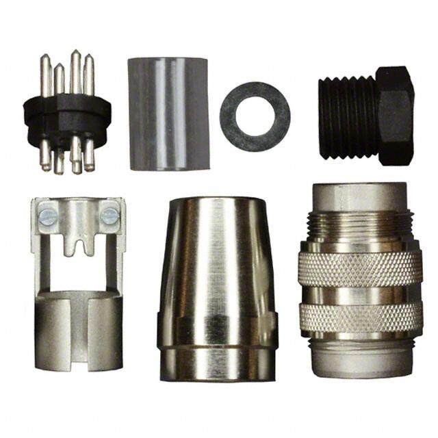
- 型号: H/MS3108B10SL-4S(73)
- 制造商: Hirose Electric
- 库位|库存: xxxx|xxxx
- 要求:
| 数量阶梯 | 香港交货 | 国内含税 |
| +xxxx | $xxxx | ¥xxxx |
查看当月历史价格
查看今年历史价格
H/MS3108B10SL-4S(73)产品简介:
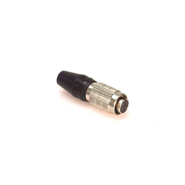
ICGOO电子元器件商城为您提供H/MS3108B10SL-4S(73)由Hirose Electric设计生产,在icgoo商城现货销售,并且可以通过原厂、代理商等渠道进行代购。 H/MS3108B10SL-4S(73)价格参考。Hirose ElectricH/MS3108B10SL-4S(73)封装/规格:圆形连接器, 2 位置 圆形连接器 插头,母型插口 焊杯 银。您可以下载H/MS3108B10SL-4S(73)参考资料、Datasheet数据手册功能说明书,资料中有H/MS3108B10SL-4S(73) 详细功能的应用电路图电压和使用方法及教程。
| 参数 | 数值 |
| 产品目录 | |
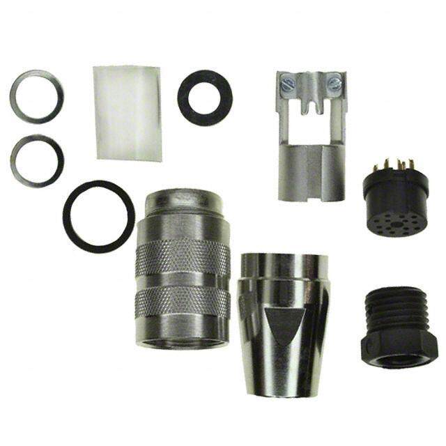
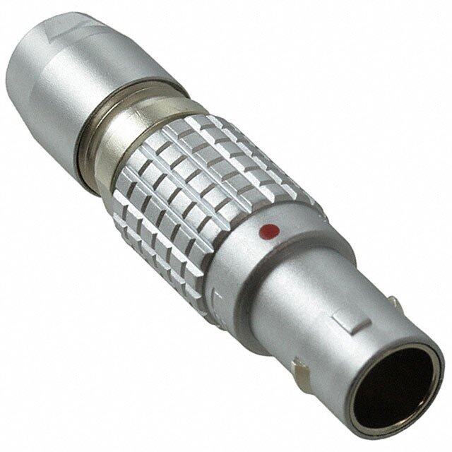
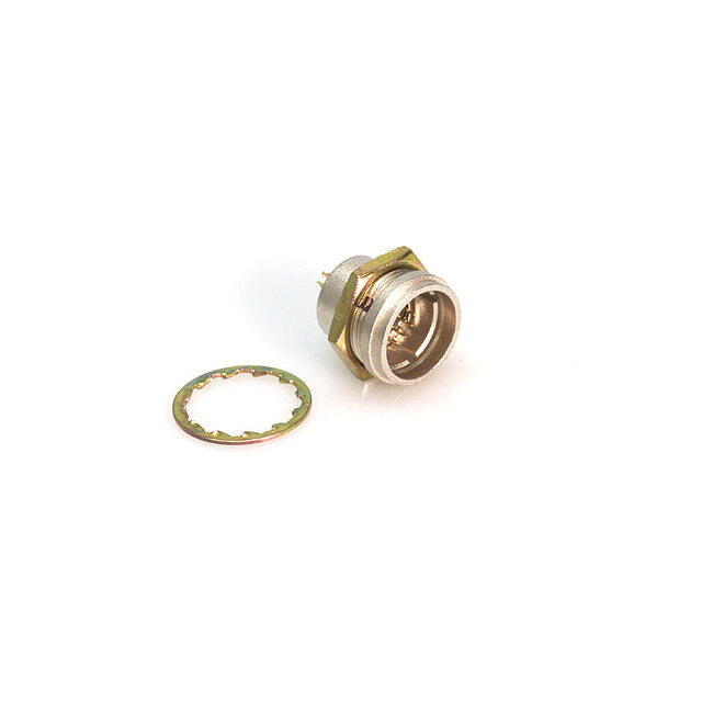
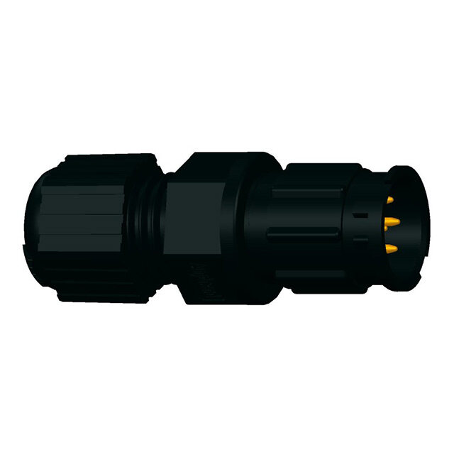
| 描述 | CONN PLUG 2POS INLINE R/A SKT环形MIL规格连接器 MS TYP LOWER PROF RA PLG SH SZ 10 FEM |
| 产品分类 | |
| 品牌 | Hirose Connector |
| MIL类型 | MIL-DTL-5015 |
| 产品手册 | |
| 产品图片 | |
| rohs | 符合RoHS无铅 / 符合限制有害物质指令(RoHS)规范要求 |
| 产品系列 | 环形MIL规格连接器,环形MIL规格连接器,Hirose Connector H/MS3108B10SL-4S(73)H/MS |
| 数据手册 | |
| 产品型号 | H/MS3108B10SL-4S(73) |
| 产品种类 | 环形MIL规格连接器 |
| 产品类型 | Plugs |
| 位置数量 | 2 |
| 侵入防护 | IP67 - 防尘,防水 |
| 其它名称 | 120-0701-8-73 |
| 包装 | 散装 |
| 商标 | Hirose Connector |
| 外壳大小 | 10 |
| 外壳尺寸-插件 | 10SL-4 |
| 外壳尺寸,MIL | - |
| 外壳材料,镀层 | - |
| 外壳类型 | Right Angle |
| 安装类型 | 自由悬挂,直角 |
| 安装角 | Right Angle |
| 工作温度 | -25°C ~ 125°C |
| 插入安排 | 10SL-4 |
| 朝向 | N(正常型) |
| 标准包装 | 1 |
| 特性 | - |
| 电压-额定 | - |
| 相关产品 | /product-detail/zh/H%2FMS3057-4A1(73)/H%2FMS3057-4A1(73)-ND/4305760/product-detail/zh/H%2FMS3057-4A(73)/H%2FMS3057-4A(73)-ND/4305759/product-detail/zh/H%2FMS3057-4A/H%2FMS3057-4A-ND/4305758 |
| 端接 | 焊杯 |
| 系列 | H/MS |
| 紧固类型 | 有螺纹 |
| 触头镀层 | 银 |
| 触头镀层厚度 | - |
| 触点材料 | Copper Alloy |
| 触点电镀 | Silver |
| 触点类型 | Socket (Female) |
| 连接器类型 | 插头,母型插口 |
| 配套产品 | /product-detail/zh/H%2FMS3102A10SL-4P(73)/H%2FMS3102A10SL-4P(73)-ND/4305763 |
| 针脚数 | 2 |
| 额定电流 | 13A |

.jpg)
.jpg)
.jpg)

- 商务部:美国ITC正式对集成电路等产品启动337调查
- 曝三星4nm工艺存在良率问题 高通将骁龙8 Gen1或转产台积电
- 太阳诱电将投资9.5亿元在常州建新厂生产MLCC 预计2023年完工
- 英特尔发布欧洲新工厂建设计划 深化IDM 2.0 战略
- 台积电先进制程称霸业界 有大客户加持明年业绩稳了
- 达到5530亿美元!SIA预计今年全球半导体销售额将创下新高
- 英特尔拟将自动驾驶子公司Mobileye上市 估值或超500亿美元
- 三星加码芯片和SET,合并消费电子和移动部门,撤换高东真等 CEO
- 三星电子宣布重大人事变动 还合并消费电子和移动部门
- 海关总署:前11个月进口集成电路产品价值2.52万亿元 增长14.8%

.jpg)
.jpg)
PDF Datasheet 数据手册内容提取
Circular Connectors Supporting TÜV and MIL spec. H/MS Series Features 1. Compatible with MIL spec. standard products 2. A ground circuit is provided in the TÜV approved connectors 3. Waterproof d. e The mated plug/receptacle combinations and v er un-mated receptacles are compliant to IP67F and s e IP68F ratings. R IP67 : Left in water at a depth of 1 m for 30 minutes s ht Product Specifi cations IP68 : Left in water at a depth of 2 m for 14 days g Ri Standard products All D. Shell size 10SL 18 20 22 T Contact arrangement 4 3 10 15 29 14 22 23 L O., s NRuamtebde cru orrf ecnotn (tAa)c/tcsontact 2 3 4 7 17 19 4 8 C g 13 13 23 23 13 13A 46 23 C atin The fi gure in [ ] indicates the total [24.5] [34.5] [76.2] [105.7] [44.2] [49.4] [152.5] [100.4] RI R capacity of the connector. T Rated voltage AC500V, DC700V C E Operation temperature range -40 to +125℃ L E Storage temperature range -10 to +60℃ E S TÜV approved products O R Shell size 10SL 18 22 24 HI Contact arrangement 3 10 22 10 8 1 Number of contacts 3 4 4 7 0 2 Rated current (A)/contact 7 10 13 17 23 17 23 23 35 46 23 35 46 23 35 ght ngs Wire size (mm2) 0.5 0.75 1.25 2 3.5 2 3.5 3.5 5.5 8 3.5 5.5 8 3.5 5.5 yri ati Rated voltage (V) 200 500 250 500 250 250 p R o Degree of pollution 3 2 3 2 3 2 C 8 Conducting voltage category Ⅲ Ⅱ Ⅲ Ⅱ Ⅲ Ⅱ 1 0 Operation temperature range -40 to +125℃ 2 1. Storage temperature range -10 to +60℃ c. e D Items Specifi cations Conditions 10SL, 20-29, 22-14 : 5mø max. 1. Contact resistance 18-10, 20-15, 22-23 : 3mø max. Measured at DC 1A 22-22, 24-10 : 1mø max. 2. Insulation resistance 5000Mø min. Measured at DC 500V TÜV approved products : AC 2250V for 1 minute. 3. Withstanding voltage No fl ashover or dielectric breakdown Standard products : See the table of contact arrangement and electrical performance. 10 to 500Hz/cycle, full amplitude : 0.75mm, with 98 m/s2, 3 directions, 3 hours each 4. Vibration Resistance No electrical discontinuity for 10µs min. 10 to 500Hz/cycle, full amplitude : 0.75mm, with 98 m/s2, 3 axis directions, 3 hours each Acceleration : 490 m/s2, duration : 11 ms, 5. Shock resistance No electrical discontinuity for 10µs min. 3 axis directions, 3 cycles each 6. Mating Cycles Contact resistance : Initial value x for 1.5mø max. 500 times -55ç : 30 minutes ➝ Normal temperature : 10 7. Temperature cycle Insulation resistance: a minimum of 500Mø to 15 minutes ➝ 125ç : 30 minutes ➝ Normal temperature : 10 to 15 minutes, left for 5 cycles Insulation resistance : Temperature : 71ç, relative humidity : 95%, left for 8. Moisture resistance a minimum of 50Mø (at high humidity) min. 336 hours 500Mø (when dry) min. Left in water at a depth of 1m for 0.5 hours in the 9. Waterproof No water penetration into the connector. mated state. Ipnl ecaassee sc ownhtaecret ath ceo ampppalincya trieopnr ewsielln dteamtivaen fdo ar fhuirgthh eler vineflo orfm raetliiaobni.lity, such as automotive, 2018.6r 1
H/MS Series●Circular Connectors Supporting TÜV and MIL spec. ■Materials / Finish Material Finish Remarks Aluminum alloy Black chromate Shell ---------------------- (Zinc alloy : H/MS3108B plug cord tube) treatment UL94V-0 Insulator PPS resin, PBT resin, or silicone rubber Black (Excluding silicone rubber) Contact Copper alloy Silver plating ---------------------- Acrylonitrile-butadiene rubber Bushing Black ---------------------- (Chloroprene rubber : H/MS08A plug) ■Product Number Structure d. e Refer to the chart below when determining the product specifications from the product number. v r e Please select from the product numbers listed in this catalog when placing orders. s e R ●Plug and receptacle s ght H/MS 3102 A 18 - 10 P X - D - T (01) Ri All ❶ ❷ ❸ ❹ ❺ ❻ ❼ ❽ ❾ ⓫ D. ●Clamp T L O., H/MS 3057 - 4A (01) C C ❶ ❷ ❿ ⓫ RI CT qModel name: H/MS Series. E L wShape : Indicates the shape of the connector. E E 3102 : Receptacle S 3106 : Straight plug O R 3108 : Right angle shaped plug 08 : Low-profi le, right angle shaped plug HI 3057 : Cord clamp 8 01 eStructure : Indicates the structure of the connector. 2 ht A : Integrated shell g B : Separated shell ri y p r Shell size : T his is the diameter of the screw (inches) at the termination end multiplied by the constant of 16. (Example : The o C shell size of 18 is calculated by 1 1/8” x 16 = 18.) 18 tContact arrangement : See pages 10 and 11 for details on contact arrangement. 0 1.2 yContact form : Indicates the termination style. c. P : Soldered, male contact e D S : Soldered, female contact PC : Crimped, male contact SC : Crimped, female contact u Variations of insert position : T he letters W, X, Y, or Z are used for any changes in the insert position from that of the standard type. i Ground contact number : Notes the grounded contact for TÜV approved products. The ground contact position corresponds to contacts C, D, or G, and varies depending on shell size. Part numbers without this symbol indicate that the part does not include a ground contact. oTÜV approved product : TÜV approved products that are compliant with DIN VDE 0627. !0Clamp size : Indicates both clamp size and structure. !1Other specifi cations : A two-digit number such as (01) or (02) is added to indicate other specifi cations. 2
H/MS Series●Circular Connectors Supporting TÜV and MIL spec. Straight plug Spanner/wrench flat width (mm) E D A D A Ø Y X B C 18−10S C H/MS3106A18-10S-D-T(73) B Standard products (Representative example) d. e Part No. HRS No. No. of contacts ØA B C D E v r H/MS3106A10SL-4S(73) 120-0601-3 73 2 ese H/MS3106A10SL-3S(73) 120-0603-9 73 3 22 36.8 5/8-24UNEF-2A ---- R H/MS3106A18-10S(73) 120-0605-4 73 4 33.5 50 1-20UNEF-2A 27 s Right HH//MMSS33110066AA2200--2299SS(W73(7)7) 112200--00661111--77 7737 17 37 54.5 10 1 3/16-18UNEF-2A 32 All H/MS3106A22-14S(73) 120-0613-2 73 19 39.5 H/MS3106A22-22S(73) 120-0615-8 73 4 D. T TÜV approved products L O., Part No. HRS No. No. of contacts ØA B C D E C H/MS3106A10SL-3S-C-T(73) 120-0326-0 73 3 22 36.8 5/8-24UNEF-2A ---- C H/MS3106A18-10S-D-T(73) 120-0323-2 73 33.5 50 1-20UNEF-2A 27 RI H/MS3106A22-22S-D-T(73) 120-0324-5 73 4 39.5 54.5 10 1 3/16-18UNEF-2A 32 T C H/MS3106A24-10S-G-T(73) 120-0325-8 73 7 43 57.7 1 7/16-18UNEF-2A 37 E L E E S Right-angled plug O R B HI 8 E 1 D 0 2 ht 18 C g ri y p o C A 8 Ø 1 0 2 Spanner/wrench flat width (mm) F 1. H/MS3108B18-10S-D-T(31) c. (Representative example) e D Standard products Part No. HRS No. No. of contacts ØA B C D E F H/MS3108B10SL-4S(73) 120-0701-8 73 2 22 37.3 24.5 5/8-24UNEF-2A 20 H/MS3108B10SL-3S(73) 120-0703-3 73 3 H/MS3108B18-10S(31) 120-0705-9 31 4 33.5 54.5 32 1-20UNEF-2A 32 H/MS3108B20-29S(31) 120-0711-1 31 11.6 17 37 35 H/MS3108B20-29SW(34) 120-0711-1 34 60.7 34 1 3/16-18UNEF-2A H/MS3108B22-14S(73) 120-0713-7 73 19 39.5 38 H/MS3108B22-22S(73) 120-0715-2 73 4 TÜV approved products Part No. HRS No. No. of contacts ØA B C D E F H/MS3108B10SL-3S-C-T(73) 120-0421-1 73 3 22 37.3 24.5 5/8-24UNEF-2A 20 H/MS3108B18-10S-D-T(31) 120-0422-4 31 33.5 54.5 32 1-20UNEF-2A 32 4 11.6 H/MS3108B22-22S-D-T(31) 120-0423-7 31 39.5 60.7 34 1 3/16-18UNEF-2A 38 H/MS3108B24-10S-G-T(73) 120-0424-0 73 7 43 67.1 39.6 1 7/16-18UNEF-2A 41 (Note) With some models it may be diffi cult to push the cable through the connector, even when the cable is within the applicable range. Waterproof performance and cable clamp capability may differ depending on the cable specifi cation. Please make sure all specifi cations are met before actual use. 3
H/MS Series●Circular Connectors Supporting TÜV and MIL spec. Low-profi le, right-angled plug (with cord clamp) 18 size : 41 (22 size : 45.8) 5 5) 3. 9. Ø3 Ø3 A D 18 ze : ze : YB CX e : 45.5e : 67.5) 18 si (22 si 18−10S zz sisi 8 2 12 ( 01−7503 d. e v H/MS08A18-10S-DT10D(73) er 18 size : 31 s e (22 size : 36) (Representative example) R s TÜV approved products ht g No. of Applicable cable Ri Part No. HRS No. Weight Solder pot diameter contacts diameter All D. H/MS08A18-10S-DT10D(73) 120-0476-3 73 89g Ø12〜14.3mm Ø2.5 T H/MS08A18-10S-DT10D1(73) 120-0481-3 73 4 Ø10〜12.5mm L O., H/MS08A22-22S-DT12D(73) 120-0477-6 73 127g Ø13〜15.9mm Ø4.5 C C RI T C E L E E S O R HI 8 1 0 2 ht g ri y p o C 8 1 0 2 1. c. e D 4
H/MS Series●Circular Connectors Supporting TÜV and MIL spec. Single block (waterproof) This connector is designed for use with flexible conduit or cabtire cable connectors.(See page 8 for the table of compatibilities for H/MS connectors and other connectors.) D A D A Ø Y X B C 18−10S C H/MS3106A-18-10S-D-T(76) B d. e (Representative example) v Standard products r e es Part No. HRS No. No. of contacts ØA B C D R s H/MS3106A10SL-3S(76) 120-0603-9 76 3 22 24 6.5 9/16-24UNEF-2A ht H/MS3106A18-10S(76) 120-0605-4 76 4 33.5 31.2 8 1-20UNEF-2A g Ri All TÜV approved products D. Part No. HRS No. No. of contacts ØA B C D T H/MS3106A18-10S-D-T(76) 120-0323-2 76 33.5 31.2 8 1-20UNEF-2A L 4 O., H/MS3106A22-22S-D-T(76) 120-0324-5 76 39.5 33.2 10 1 1/4-18UNEF-2A C C Receptacle (solder type) RI T C E B L ØC E A E S O R D A HI B A H 8 C B Ø 1 X Y 0 18−10 2 ht D E g I yri F p H/MS3102A18-10P-D-T1(73) o G C 8 Standard products (Representative example) 1 0 2 Part No. HRS No. No. of contacts A B ØC D E F G ØH I 1. c. H/MS3102A10SL-4P(73) 120-0111-4 73 2 18.26 25.4 14.5 2.2 23.6 28.3 15.6 5/8-24UNEF-2A e H/MS3102A10SL-3P(73) 120-0113-0 73 3 D H/MS3102A18-10P(73) 120-0101-0 73 4 26.97 34.92 30 26.6 1 1/8-18UNEF-2A 35 H/MS3102A20-15P(73) 120-0115-5 73 7 3.3 H/MS3102A20-29P(73) 120-0103-6 73 29.36 38.1 19.3 2.8 29.6 1 1/4-18UNEF-2A 17 29.4 33 H/MS3102A20-29PW(74) 120-0103-6 74 H/MS3102A22-22P(73) 120-0107-7 73 4 31.75 41.28 38 32.6 1 3/8-18UNEF-2A TÜV approved products Part No. HRS No. No. of contacts A B ØC D E F G ØH I H/MS3102A10SL-3P-C-T(73) 120-0231-6 73 3 18.26 25.4 14.5 2.2 23.6 28.3 15.6 5/8-24UNEF-2A H/MS3102A18-10P-D-T1(73) 120-0259-5 73 26.97 34.92 3.3 30 35 26.6 1 1/8-18UNEF-2A 4 19.3 H/MS3102A22-22P-D-T(73) 120-0227-9 73 31.75 41.28 2.8 29.4 38 32.6 1 3/8-18UNEF-2A H/MS3102A24-10P-G-T(73) 120-0228-1 73 7 34.92 44.45 3.75 21 31.6 41 36 1 1/2-18UNEF-2A 5
H/MS Series●Circular Connectors Supporting TÜV and MIL spec. Receptacle (crimp type) B ØC A M A L T NPBC B A KWJHS20−29PREZD ØH G F D E I F d. G rve H/MS3102A20-29PC(73) (Representative example) e s e R s Standard products ht g Ri Part No. HRS No. No. of A B ØC D E F G ØH I All contacts D. H/MS3102A20-29PC(73) 120-0501-9 73 17 29.36 38.1 3.3 19.3 2.8 29.4 37 29.6 1 1/4-18UNEF-2A T H/MS3102A22-14PC(73) 120-0502-1 73 19 31.75 41.28 32.6 1 3/8-18UNEF-2A L O., C C RI Contact T C Male contact E L E Applicable wire E Type Part No. HRS No. OS Ø2.8 Reel contacts H/MS-PC1-212 120-0533-5 size R 28.5 HI Loose piece AWG#24〜28 8 contacts H/MS-PC1-112 120-0534-8 1 20 (Note) Reel contacts are packaged 7,000 pcs/reel. Loose piece contacts ht are packaged 100 pcs/pack. g ri y p o C 8 Receptacle mounting method 1 20 When installing a waterproof receptacle, please insert the appropriate O-ring (to be placed between the receptacle and 1. panel), as shown in the figure on the right. c. e D Mounting panel Recommended O-ring dimensions. O-ring Inner diameter Thickness of Part No. ØA of O-ring (Ø) O-ring (Ø) H/MS3102A10SL-** 17.5 17.5 1.5 H/MS3102A18-** 28.5 28.5 A H/MS3102A20-** 31.5 31.5 Ø 2 H/MS3102A22-** 34.5 34.5 H/MS3102A-24 ** 37.8 37.5 H/MS connector 6
H/MS Series●Circular Connectors Supporting TÜV and MIL spec. Cord clamp A D Ø Ø B Spanner/wrench flat width (mm) C E d. e v H/MS3057-10A(31) er (Representative example) s e R s Waterproof type ht g Ri Part No. HRS No. ØA B C ØD E Range of applicable cable Applicable shell All diameters (reference) size D. H/MS3057-4A(73) 120-0801-2 73 20 26.8 83.8 5.6 17 Ø3.1〜5.6 10SL T H/MS3057-10A(31) 120-0802-5 31 30 28.8 72.8 14.3 27 Ø10.3〜14.3 18 L O., H/MS3057-12A(31) 120-0803-8 31 34 29.8 70.8 15.9 30 Ø11.4〜15.9 20.22 C H/MS3057-16A(73) 120-0804-0 73 40 33.8 69.3 19 36 Ø14〜19 24 C RI (Remarks) F or various cable diameters, clamping force and waterproof performance may differ depending on the cable type T selected. Please make sure all specifi cations are met before assembly. C E L E E S Applicable tools O R HI Type Item Part No. HRS No. Applicable contact Applicable wire size 8 Manual 1 Manual H/MS/CC-HT 150-0206-0 H/MS-PC1-112 AWG#24〜28 0 crimping tool 2 ht Automatic CM-105C 901-0001-0 ---------------------- ---------------------- rig Auto crimping press y p Applicator AP105-H/MS-PC1-1 901-2027-8 H/MS-PC1-212 AWG#24〜28 o C H/MS-PC1-112 8 Extraction tool H/MS-TP 150-0076-7 ---------------------- 1 H/MS-PC1-212 0 2 1. c. e D Manual crimping tool Extraction tool Automatic crimping press (CM-105C) 7
H/MS Series●Circular Connectors Supporting TÜV and MIL spec. Connector combinations Cord clamp d. e v Right-angled plug r e s e R s Connector for cabtire cable ht g Ri All D. Straight plug T L O., C C RI Connector for fl exible conduit T C E L E E S O R HI Receptacle 8 1 0 2 ht g ri y p o C 8 Low-height, right-angled plug 1 0 2 1. c. e Straight connector for flexible D conduit and cabtire cable Single block Straight connector for fl exible conduit and cabtire cable (Remarks) 1. Illustration represents connectors for fl exible conduit and cabtire cable as a reference example. 2. The standard and TÜV approved products are compatible with each other. When using the TÜV approved products for TÜV applications, make sure to use both TÜV approved plugs and receptacles together. 8
H/MS Series●Circular Connectors Supporting TÜV and MIL spec. Table of compatibilities for H/MS connectors and the connectors for conduit and cabtire cable Connectors for flexible conduit Part number by Nippon Flex Co., Ltd. Part number by Daiwa Dengyo Co., Ltd. H/MS connector Part No. Straight type Right angle type Straight type Right angle type H/MS3106A10SL-□□(73) RCC10*CA12 (with O-ring) NBDC 12S** (with O-ring) --------- --------- H/MS3108B10SL-□□(73) RCC10*CA12 NBDC 12S** H/MS3106A10SL-□□(76) RCC10*RL-MS10F RCC-30*RL-MS10F BOS 10* BOL 10* H/MS3106A18-□□(73) RCC10*CA18 (with O-ring) NBDC 18** (with O-ring) --------- --------- H/MS3108B18-□□(73) RCC10*CA18 NBDC 18** H/MS3106A18-□□(76) RCC10*RL-MS18F RCC-30*RL-MS18F BOS 18** BOL 18** d. e H/MS3106A20-□□(73) RCC10*CA2022 (with O-ring) NBDC 20(22)** (with O-ring) v --------- --------- er H/MS3106B20-□□(73) RCC10*CA2022 NBDC 20(22)** s Re H/MS3106A20-□□(76) RCC10*RL-MS20F RCC-30*RL-MS20F BOS 22** BOL 20** hts H/MS3106A22-□□(73) RCC10*CA2022 (with O-ring) --------- NBDC 20(22)** (with O-ring) --------- Rig H/MS3108B22-□□(73) RCC10*CA2022 NBDC 20(22) All H/MS3106A22-□□(76) RCC10*RL-MS22F RCC-30*RL-MS22F BOS 22** BOL 22** D. H/MS3106A24-□□(73) CC10*CA2428 (with O-ring) NBDC 24** (with O-ring) --------- --------- LT H/MS3108B24-□□(73) RCC10*CA2428 NBDC 24** O., H/MS3106A24-□□(76) RCC10*RL-M524F RCC-30*RL-MS24F BOS 24** BOL 24** C C Connectors for cabtire cable RI T Part number by Nippon Flex Co., Ltd. Part number by Daiwa Dengyo Co., Ltd. C H/MS connector LE Part No. Straight type Right angle type Straight type Right angle E type E H/MS3106A-10SL□□(73) YDC 12S* (with O-ring) S --------- --------- --------- O H/MS3108B-10SL□□(73) YDC 12S* R HI H/MS3106A-10SL□□(76) ACS**RL-MS10F ACA**RL-MS10F YDO 10* YLO 10* 8 1 H/MS3106A18-□□(73) YDC 18** (with O-ring) 0 ACS**CA18 --------- --------- 2 H/MS3108B18-□□(73) YDC 18** ht g H/MS3106A18-□□(76) ACS**RL-MS18F ACA**RL-MS18F YDO 18** YLO 18* ri py H/MS3106A20-□□(73) YDO 20(22)** (with O-ring) o ACS**CA2022 --------- --------- C H/MS3106B20-□□(73) YDC 20(22)** 8 H/MS3106A20-□□(76) ACS**RL-MS20F ACA**RL-MS20F YDC 20** YLO 20* 1 0 2 H/MS3106A22-□□(73) YDC 20(22)** (with O-ring) 1. ACS**CA2022 --------- --------- c. H/MS3108B22-□□(73) YDC 20(22)** e D H/MS3106A22-□□(76) ACS**RL-MS22F ACA**RL-MS22F YDO 22** YLO 22* H/MS3106A24-□□(73) YDC 24** (with O-ring) ACS**CA2428 --------- --------- H/MS3108B24-□□(73) YDC 24** H/MS3106A24-□□(76) ACS**RL-MS24F ACA**RL-MS24F YDO 24** YLO 24* (Remarks) 1. □□: Indicates contact arrangement/count. 2. ** : The values differ depending on the cable used. 9
H/MS Series●Circular Connectors Supporting TÜV and MIL spec. Contact arrangement and electrical performance Shell size 10SL 18 20 4 3 10 15 29 Contact arrangement d. e v Number of er 2 3 4 7 17 s contacts e R Withstanding AC 1,000V AC 2,000V s voltage for 1minute for 1minute ht g Current Ri capacity 13A(24.5A) 13A(34.5A) 23A(76.2A) 23A(105.7A) 13A(44.2A) All Insulation D. resistance 5,000Mø min. at 500V DC T Contact L 5mø max. 3mø max. 5mø max. O., resistance C Inner diameter Ø1.8 Ø2.9 Ø1.8 C of solder pot RI Preliminary T Not necessary Needed Not necessary C soldering E L E Shell size 22 E S 14 22 23 O R HI 8 1 0 2 Contact ht arrangement g ri y p o C 8 1 0 2 Number of 1. 19 4 8 c. contacts e Withstanding AC 2,000V D voltage for 1minute Current 13A(49.4A) 46A(152.5A) 23A(100.4A) capacity Insulation 5,000Mø min. at 500V DC resistance Contact 5mø max. 1mø max. 3mø max. resistance Inner diameter Ø1.8 Ø5.3 Ø2.9 of solder pot Preliminary Not necessary Needed soldering Remarks 1. Figure shows the receptacle contact arrangement as viewed from the interface mating side (plug's socket insert side). 2. Withstanding voltages are derived from test voltages 3. Current capacities are shown in a value per contact. The number in ( ) indicates the connector's total capacity. 4. Contact resistances are shown in a value when measured at DC 1 A. 5. Please contact us for more information. 10
H/MS Series●Circular Connectors Supporting TÜV and MIL spec. Major specifi cations of TÜV approved products Applicable German standard: DIN VDE0627 (connector) Shell size 10SL 18 22 24 3 10 22 10 Contact arrangement d. e v r e s e Number of contacts 3 4 4 7 R s Ground contact No. C D D G Right AC/DC ra(Vte)d voltage 200 500 250 500 250 250 All Rated current (A) 7 10 13 17 23 17 23 23 35 46 23 35 46 23 35 D. Wire size (mm2) 0.5 0.75 1.25 2 3.5 2 3.5 3.5 5.5 8 3.5 5.5 8 3.5 5.5 T L Degree of Pollution 3 2 3 2 3 2 O., Conducting voltage C Ⅲ Ⅱ Ⅲ Ⅱ Ⅲ Ⅱ C category RI Inner diameter of Plug: Ø3.6 Ø1.8 Ø2.6 Ø4.5 T solder pot (mm) Receptacle: Ø5.3 C E L Remarks E E 1. Figure shows the receptacle contact arrangement as viewed from the interface mating side (plug's socket insert side). S O 2. Current capacities are shown in a value per contact. R 3. The contact numbers with a mark "◎" have contacts that are grounded to the outer shell, except for receptacles that are size HI 24-10. 8 1 4. For the receptacles that are size 24-10, the ground contact (contact No.: G) does not ground with the outer shell. Please use 0 2 these connectors after grounding the outer shell of the connector with the corresponding contact No. ht 5. The degree of pollution and conducting voltage categories refer to the environmental condition in which a DIN VDE0110 g ri (insulation coordination for the electric appliances in a constant voltage facility) electric appliance is used, and to the class of y p over voltage in the electric appliance. o C 6. Performance values for other than those shown above are the same as those of the general H/MS series. 8 1 0 Usage Recommendations 2 1. c. (1) The power to the circuit should always be off before mating/unmating a connector. e D (2) Always use a female connector for the power side of the circuit; this will prevent the likelihood of electric shocks. (3) Be sure to fully tighten the lock mechanism of the connectors. (4) Connector performance features such as cable clamping force, cable rotation force, or waterproof performance may differ depending on the cable construction. Please make sure all specifi cations are met before assembly. (5) This product uses silver-plated contacts. Please be aware that silver easily reacts to sulfur gases, causing discoloration or degradation when exposed to certain environmental conditions as shown below. These conditions include areas with: • A large amount of dust and dirt • High density of sulfur dioxide gas, hydrogen sulfi de gas, nitrogen dioxide gas, or other gas (Emission gases from vehicles and factories, etc.) • Highly fl uctuating temperatures, such as close to a heating apparatus In addition, it is recommended to store the products in their original packaging or similar state in order to prevent discoloration. • Temperature: -10 to +60°C, relative humidity: 80% or lower (An environment where temperature and relative humidity are constant and there is less temperature difference is recommended.) • Please use the products within six months after delivery. (For the products in which the storage period is expired, please confirm the ease of soldering for your application beforehand.) 11
H/MS Series●Circular Connectors Supporting TÜV and MIL spec. USA: USA: USA: HIROSE ELECTRIC (U.S.A.), INC. HEADQUARTERS CHICAGO OFFICE HIROSE ELECTRIC (U.S.A.), INC. SAN JOSE OFFICE HIROSE ELECTRIC (U.S.A.), INC. DETROIT OFFICE (AUTOMOTIVE) 2300 Warrenville Road, Suite 150, 2841 Junction Ave, Suite 200 17197 N. Laurel Park Drive, Suite 253, Downers Grove, IL 60515 San Jose, CA. 95134 Livonia, MI 48152 Phone : +1-630-282-6700 Phone : +1-408-253-9640 Phone : +1-734-542-9963 http://www.hirose.com/us/ Fax : +1-408-253-9641 Fax : +1-734-542-9964 http://www.hirose.com/us/ http://www.hirose.com/us/ USA: THE NETHERLANDS: GERMANY: HIROSE ELECTRIC (U.S.A.), INC. BOSTON OFFICE HIROSE ELECTRIC EUROPE B.V. HIROSE ELECTRIC EUROPE B.V. GERMAN BRANCH 300 Brickstone Square Suite 201, Hogehillweg #8 1101 CC Amsterdam Z-O Schoenbergstr. 20, 73760 ostfildern Andover, MA 01810 Phone : +31-20-6557460 Phone : +49-711-456002-1 Phone : +1-978-662-5255 Fax : +31-20-6557469 Fax : +49-711-456002-299 http://www.hirose.com/eu/ http://www.hirose.com/eu/ d. e v r e s e GERMANY: GERMANY: FRANCE: R s HIROSE ELECTRIC EUROPE B.V. NUREMBERG OFFICE HIROSE ELECTRIC EUROPE B.V. HANOVER OFFICE HIROSE ELECTRIC EUROPE B.V. PARIS OFFICE ht Neumeyerstrasse 22-26, 90411 Nurnberg Bayernstr. 3, Haus C 30855 Langenhagen, Germany 130 Avenue Joseph Kessel, Bat E, 78960 g Ri Phone : +49-911 32 68 89 63 Phone : +49-511 97 82 61 30 Voisins le Bretonneux, France All Fax : +49-911 32 68 89 69 Fax : +49-511 97 82 61 35 Phone : +33-1-85764886 http://www.hirose.com/eu/ http://www.hirose.com/eu/ Fax : +33-1-85764823 D. http://www.hirose.com/eu/ T L O., UNITED KINGDOM: CHINA: CHINA: C HIROSE ELECTRIC EUROPE BV (UK BRANCH) HIROSE ELECTRIC (CHINA) CO., LTD. (SHANGHAI, HEADQUARTERS) HIROSE ELECTRIC (CHINA) CO.,LTD. BEIJING BRANCH C 4 Newton Court, Kelvin Drive, Knowlhill, 18, Enterprise Center Tower 2, 209# Gong He A1001, Ocean International Center, Building 56# East 4th RI T Milton Keynes, MK5 8NH Road, Jing’an District, Shanghai, CHINA 200070 Ring Middle Road, ChaoYang District, Beijing, 100025 C Phone : +44-1908 202050 Phone : +86-21-6391-3355 Phone : +86-10-5165-9332 E L Fax : +44-1908 202058 Fax : +86-21-6391-3335 Fax : +86-10-5908-1381 E E http://www.hirose.com/eu/ http://www.hirose.com/cn/ http://www.hirose.com/cn/ S O R CHINA: HONG KONG: TAIWAN: HI HIROSE ELECTRIC (CHINA) CO., LTD. SHENZHEN BRANCH HIROSE ELECTRIC HONGKONG TRADING CO., LTD. HIROSE ELECTRIC TAIWAN CO., LTD. 8 Room 09-13, 19/F, Office Tower Shun Hing Square, Di Wang Commercial Centre, Room 1001, West Wing, Tsim Sha Tsui Centre, 66 103 8F, No.87, Zhengzhou Rd., Taipei 1 0 5002 Shen Nan Dong Road, Shenzhen City, Guangdong Province, 518008 Mody Road, Tsim Sha Tsui East, Kowloon, Hong Kong Phone : +886-2-2555-7377 2 ht Phone : +86-755-8207-0851 Phone : +852-2803-5338 Fax : +886-2-2555-7355 g Fax : +86-755-8207-0873 Fax : +852-2591-6560 http://www.hirose.com/tw/ ri y http://www.hirose.com/cn/ http://www.hirose.com/hk/ p o C 8 KOREA: SINGAPORE: INDIA: 1 HIROSE KOREA CO.,LTD. HIROSE ELECTRIC SINGAPORE PTE. LTD. HIROSE ELECTRIC SINGAPORE PTE. LTD. DELHI LIAISON OFFICE 0 2 143, Gongdan 1-daero, Siheung-si, 03, Anson Road, #20-01, Springleaf Tower, Office NO.552, Regus-Green Boulevard, Level5, Tower C, 1. c. Gyeonggi-do, 15084, Korea Singapore 079909 Sec62, Plot B-9A, Block B, Noida, 201301, Uttar Pradesh, India e Phone : +82-31-496-7000 Phone : +65-6324-6113 Phone : +91-12-660-8018 D Fax : +82-31-496-7100 Fax : +65-6324-6123 Fax : +91-120-4804949 http://www.hirose.co.kr/ http://www.hirose.com/sg/ http://www.hirose.com/sg/ INDIA: MALAYSIA: THAILAND: HIROSE ELECTRIC SINGAPORE PTE. LTD. BANGALORE LIAISON OFFICE PENANG REPRESENTATIVE OFFICE BANGKOK OFFICE (REPRESENTATIVE OFFICE) Unit No-403, 4th Floor, No-84, Barton Centre, Mahatma 73-3-1, Ideal@The One, Jalan Mahsuri, Bayan Unit 4703, 47th FL., 1 Empire Tower, South Sathorn Gandhi (MG) Road, Bangalore 560 001, Karnataka, India Lepas Penang, 11950, Malaysia Road, Yannawa, Sathorn, Bangkok 10120 Thailand Phone : +91-80-4120 1907 Phone : +604-648-5536 Phone : +66-2-686-1255 Fax : +91-80-4120 9908 http://www.hirose.com/sg/ Fax : +66-2-686-3433 http://www.hirose.com/sg/ http://www.hirose.com/sg/ ® 2-6-3,Nakagawa Chuoh,Tsuzuki-Ku,Yokohama-Shi 224-8540,JAPAN TEL: +81-45-620-3526 Fax: +81-45-591-3726 http://www.hirose.com http://www.hirose-connectors.com The characteristics and the specifications contained herein are for reference purpose. Please refer to the latest customer drawings prior to use. 12 The contents of this catalog are current as of date of 06/2018. Contents are subject to change without notice for the purpose of improvements. Powered by TCPDF (www.tcpdf.org)
Mouser Electronics Authorized Distributor Click to View Pricing, Inventory, Delivery & Lifecycle Information: H irose Electric: H/MS3108B10SL-3S-C-T(73) H/MS3102A10SL-3P-C-T(73) H/MS3106A20-29S(73) H/MS08A18-10S-DT10C(74) H/MS08A18-10S-DT10D(73) H/MS08A22-22S-DT12D(73) H/MS08A22-22S-DT12D1(73) H/MS3102A10SL-3P(73) H/MS3102A10SL-4P(73) H/MS3102A18-10P(73) H/MS3102A18-10P-D-T1(73) H/MS3102A20-15P(73) H/MS3102A20-29P(73) H/MS3102A20-29P(76) H/MS3102A20-29PW(74) H/MS3102A20-29PZ(75) H/MS3102A22- 14P(73) H/MS3102A22-14PC(73) H/MS3102A22-14P-N(73) H/MS3102A22-22P(73) H/MS3102A22-22P-D-T(73) H/MS3106A10SL-3S(73) H/MS3106A10SL-3S-C-T(73) H/MS3106A10SL-3S-C-T(76) H/MS3106A10SL-4S(73) H/MS3106A18-10S(73) H/MS3106A18-10S(76) H/MS3106A18-10S-D-T(73) H/MS3106A18-10S-D-T(76) H/MS3106A20-15S(73) H/MS3106A20-29SW(77) H/MS3106A20-29SW(78) H/MS3106A22-14S(73) H/MS3106A22- 22S(73) H/MS3106A22-22S-D-T(73) H/MS3106A22-22S-D-T(76) H/MS3106A22-23S-D(73) H/MS3106A24-10S(76) H/MS3106A24-10S-G-T(76) H/MS3108B10SL-3S(73) H/MS3108B10SL-4S(73) H/MS3108B18-10S(73) H/MS3108B18-10S-D(73) H/MS3108B18-10S-D-T(73) H/MS3108B20-29S(73) H/MS3108B20-29SW(74) H/MS3108B22-14S(73) H/MS3108B22-22S(73) H/MS3108B22-22S-D(73) H/MS3108B22-22S-D-T(73) H/MS3108B24-10S-G-T(73) H/MSA3106A10SL-3S(73) H/MSA3108B10SL-3S(73) H/MS08A18-10S-DT10D1(73) H/MS08A22-22S-DT12D(74) H/MS3102A20-29PC(73) H/MS3102A24-10P-G-T(73) H/MS3106A22-14S-N(73) H/MSA3108B22-22S(73) H/MS3106A10SL-3S(76)

 Datasheet下载