ICGOO在线商城 > 传感器,变送器 > 光学传感器 - 光断续器 - 槽型 - 逻辑输出 > GP1A75EJ000F
 Datasheet下载
- 型号: GP1A75EJ000F
- 制造商: Sharp Microelectronics
- 库位|库存: xxxx|xxxx
- 要求:
| 数量阶梯 | 香港交货 | 国内含税 |
| +xxxx | $xxxx | ¥xxxx |
查看当月历史价格
查看今年历史价格
GP1A75EJ000F产品简介:
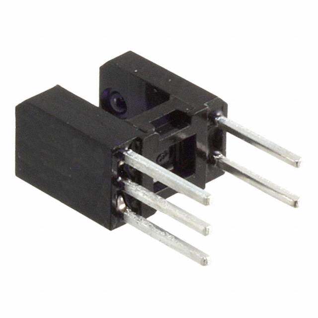
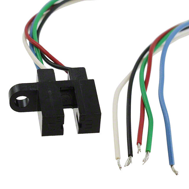
ICGOO电子元器件商城为您提供GP1A75EJ000F由Sharp Microelectronics设计生产,在icgoo商城现货销售,并且可以通过原厂、代理商等渠道进行代购。 GP1A75EJ000F价格参考。Sharp MicroelectronicsGP1A75EJ000F封装/规格:光学传感器 - 光断续器 - 槽型 - 逻辑输出, Optical Sensor Transmissive 0.197" (5mm) Module, Connector。您可以下载GP1A75EJ000F参考资料、Datasheet数据手册功能说明书,资料中有GP1A75EJ000F 详细功能的应用电路图电压和使用方法及教程。
Sharp Microelectronics的GP1A75EJ000F是一款光学传感器,具体分类为光断续器(光电开关)中的槽型传感器,并具有逻辑输出功能。这种传感器广泛应用于各种需要检测物体存在、位置或运动状态的场合,特别是在自动化控制和工业应用中。

 应用场景

1. 自动化设备:在自动化工厂中,GP1A75EJ000F可以用于检测传送带上的物品是否存在。例如,在包装线上,当有物体通过传感器时,它会触发信号,通知控制系统进行下一步操作,如封箱、贴标签等。

2. 计数与限位检测:该传感器可用于计数系统,例如在生产线中统计通过的零件数量。它还可以作为限位开关,确保机械臂或其他移动部件在预定范围内工作,防止超出安全范围。

3. 电梯与扶梯:在电梯门或自动扶梯入口处安装GP1A75EJ000F,可以检测是否有物体(如手提包或脚)卡在门缝中,从而避免夹伤事故。此外,它还可以用于检测电梯轿厢是否到达指定楼层。

4. 办公设备:打印机、复印机等办公设备中,GP1A75EJ000F可以用于纸张检测。当纸张通过传感器时,它可以确认纸张的存在并启动打印过程,或者检测到卡纸情况并发出警报。

5. 家用电器:在一些家用电器中,如洗衣机、洗碗机等,该传感器可以用于检测门是否关闭到位,确保机器在安全状态下运行。

6. 安防系统:在某些安防系统中,GP1A75EJ000F可以用作门窗开关状态的检测。当门窗被打开时,传感器会发出信号,触发报警系统。

7. 机器人与无人机:在机器人或无人机中,GP1A75EJ000F可以用于避障或路径规划。通过检测障碍物的位置,机器人可以调整其行进路线,避免碰撞。

总之,GP1A75EJ000F凭借其高精度和可靠性,适用于多种应用场景,尤其在需要精确检测物体位置或运动状态的领域表现出色。
| 参数 | 数值 |
| 产品目录 | |
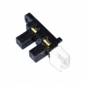
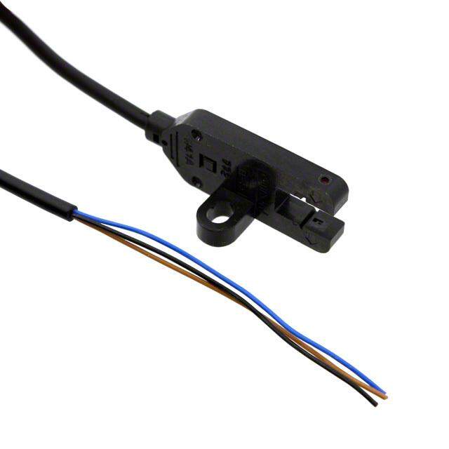
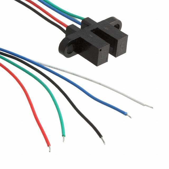
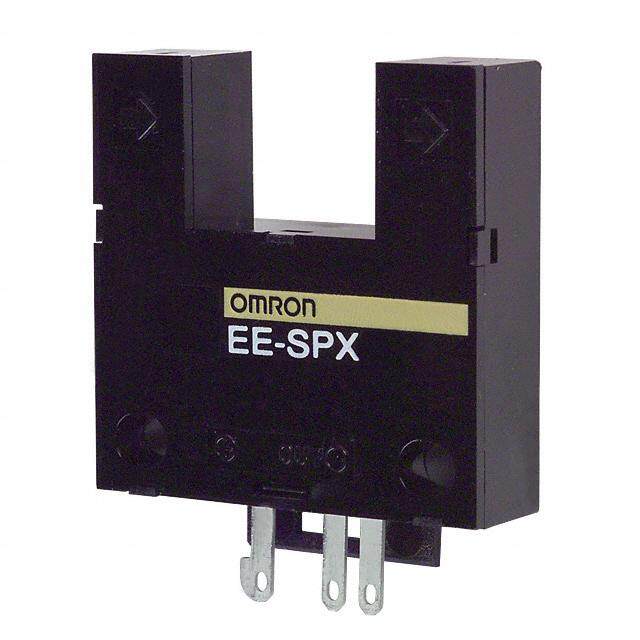
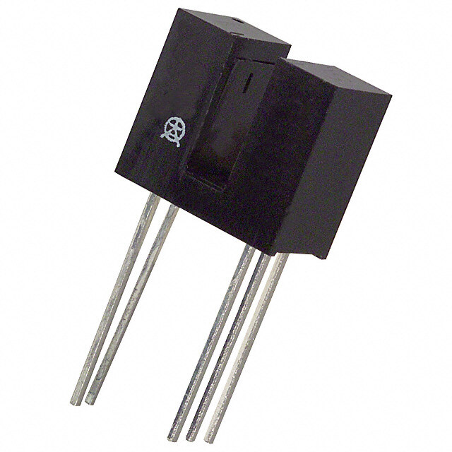
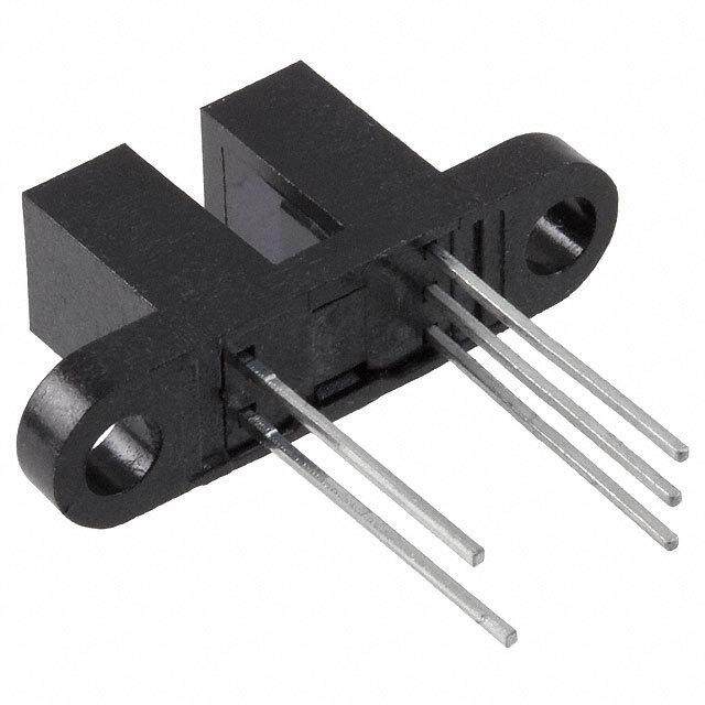
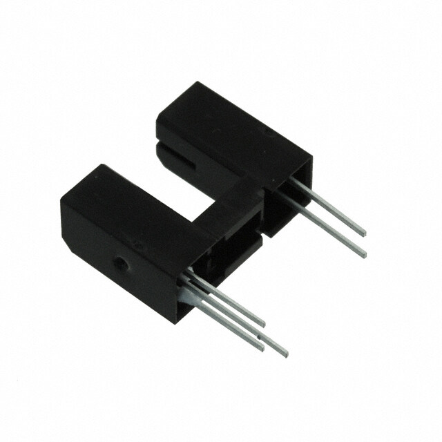
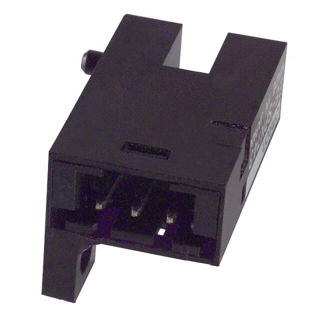
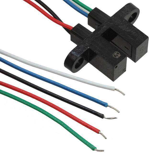
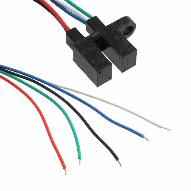
| 描述 | PHOTOINTER OPIC SLOT 5.0MM W/CON光学开关(透射型,光电IC输出) OPIC Photointerruptr Cnctr Gap/Silt 5.0mm |
| 产品分类 | |
| 品牌 | Sharp Microelectronics |
| 产品手册 | |
| 产品图片 |
|
| rohs | 符合RoHS无铅 / 符合限制有害物质指令(RoHS)规范要求 |
| 产品系列 | 光学开关(透射型,光电IC输出),Sharp Microelectronics GP1A75EJ000FOPIC™ |
| 数据手册 | http://www.sharpsma.com/webfm_send/637 |
| 产品型号 | GP1A75EJ000F |
| PCN设计/规格 | http://www.sharpsma.com/webfm_send/1525 |
| 产品目录页面 | |
| 产品种类 | 光学开关(透射型,光电IC输出) |
| 低电平输出电压 | 0.35 V |
| 低电平输出电流 | 16 mA |
| 光圈宽度 | 0.5 mm |
| 其它名称 | 425-1954-5 |
| 响应时间 | - |
| 商标 | Sharp Microelectronics |
| 安装类型 | 底座安装 |
| 封装/外壳 | 模块,连接器 |
| 工厂包装数量 | 100 |
| 感应方式 | Transmissive, Slotted |
| 感应方法 | 可传导的 |
| 感应距离 | 0.197"(5mm) |
| 最大工作温度 | + 75 C |
| 最小工作温度 | - 20 C |
| 标准包装 | 100 |
| 槽宽 | 5 mm |
| 电压-电源 | 4.5 V ~ 5.5 V |
| 电流-电源 | 20mA |
| 输出设备 | Pull Up, Buffer |
| 输出配置 | 上拉电阻,缓冲器 |


- 商务部:美国ITC正式对集成电路等产品启动337调查
- 曝三星4nm工艺存在良率问题 高通将骁龙8 Gen1或转产台积电
- 太阳诱电将投资9.5亿元在常州建新厂生产MLCC 预计2023年完工
- 英特尔发布欧洲新工厂建设计划 深化IDM 2.0 战略
- 台积电先进制程称霸业界 有大客户加持明年业绩稳了
- 达到5530亿美元!SIA预计今年全球半导体销售额将创下新高
- 英特尔拟将自动驾驶子公司Mobileye上市 估值或超500亿美元
- 三星加码芯片和SET,合并消费电子和移动部门,撤换高东真等 CEO
- 三星电子宣布重大人事变动 还合并消费电子和移动部门
- 海关总署:前11个月进口集成电路产品价值2.52万亿元 增长14.8%
PDF Datasheet 数据手册内容提取
GP1A75E GP1A75E Small Size OPIC Photointerrupter with Connector n Features n Outline Dimensions (Unit: mm) 1. 3-pin connector terminal Internal connection diagram 2. High sensing accuracy (6.8) Voltage regulator (Slit width: 0.5mm) Amp. )8 1 15kW 3. Wide gap between light emitter 3.2 (7. 2 f and detector (5mm ) 2.5 3 24 JAPAN AMP made connector No.175487-3 n Applications Case surface 4.7 1. Copiers 9.6 13.6 2.6 2 2.35 2. Laser beam printers 4.3 5 4.3 6.8±1.0 ±0. 2-0.5±0.1 5 Slit width 3. Facsimiles 1. 2 7. )8 5.6 (5. 18.1 2.4 11.8 30.32 0.9+-00..2151 23 1 GND 2 VOUT 2- 3 VCC R3.2 * Unspecified tolerances shall be as follows; Dimensions(d)Tolerance d<5.0 ±0.15 5.0<=d<15.0 ±0.2 Chip resistor 15.0<=d ±0.3 * ( ): Reference dimensions *“OPIC”( Optical IC) is a trademark of the SHARP Corporation. An OPIC consists of a light-detecting element and signal- processing circuit integrated onto a single chip. n Absolute Maximum Ratings (Ta= 25˚C) Parameter Symbol Rating Unit Supply voltage VCC -0.5 to+10 V *1Low level output current IOL 50 mA *2Operating temperature Topr -20 to+75 ˚C *2Storage temperature Tstg -30 to+85 ˚C *1 Collector current of output transistor *2 The connector should be plugged in/out and the unit's hook should be used at normal termperature. “In the absence of confirmation by device specification sheets, SHARP takes no responsibility for any defects that occur in equipment using any of SHARP's devices, shown in catalogs, data books, etc. Contact SHARP in order to obtain the latest version of the device specification sheets before using any SHARP's device.”
GP1A75E n Electro-optical Characteristics (Unless otherwise specified, V = 5V,Ta=25˚C) CC Parameter Symbol Conditions MIN. TYP. MAX. Unit Operating supply voltage VCC - 4.5 - 5.5 V Low level supply current ICCL Light beam interruped - - 20 mA Low level output voltage VOL Light beam interruped, IOL=16mA - - 0.35 V High level supply current ICCH Light beam uninterruped - - 20 mA High level output voltage VOH Light beam uninterruped VCCx0.9 - - V Minimum interruption tH - 166 - - m s Response time characteristics Minimum sensing tL - 166 - - m s time Fig. 1 Low Level Output Current vs. Fig. 2 Low Level Output Voltage vs. Ambient Temperature Low Level Output Current 60 1.0 VCC=5V )A 50 )V 0.5 Ta=25˚C (w level output current I mOL 432000 - 0.67mA/˚C (ow level output voltage V OL 000.0..125 o L L 10 0.02 0 0.01 -25 0 25 50 75 100 1 2 5 10 20 50 100 -20 Ambient temperature Ta (˚C) Low level output current IOL (mA) Fig. 3 Low Level Output Voltage vs. Fig. 4 Supply Current vs. Supply Voltage Ambient Temperature 0.6 30 VCC=5V 0.5 ()ge V VOL 0.4 () mACC 20 Ta=- 20˚+C25˚C w level output volta 00..32 IOL=30mA16m5AmA Supply current I 10IICCCCLH T+a=2-52˚C0˚,+C,75˚C+75˚C Lo 0.1 0 0 -25 0 25 50 75 100 4.5 5.0 5.5 Ambient temperature Ta (˚C) Supply voltage VCC (V)
GP1A75E Fig. 5 Detecting Position Characteristics (1) Fig. 6 Detecting Position Characteristics (2) VCC=5V,Ta=25˚C VCC=5V Detecting position Ta=25˚C d=2.35±0.3mm Output High Detecting position Output High h=3.0±1.0mm 0d h 0 Output Low Output Low 0 1 2 3 4 5 0 1 2 3 4 5 Shield distance d (mm) Shield distance h (mm) n Recommended Mounting Holes (Unit: mm) 3.2 f 3 9. 1 6 2. 8.2 Mounting method n Precautions for Use (1) In this product, the PWB is fixed with a hook, and cleaning solvent may remain inside the case; therefore, dip cleaning or ultrasonic cleaning are prohibited. (2) Remove dust or stains, using an air blower or a soft cloth moistened in cleaning solvent. In this case, use only the following type of cleaning solvent used for wiping off: Ethyl alcohol, Methyl alcohol, Isopropyl alcohol When the cleaning solvents except for specified materials are used, please consult us. (3) In order to stabilize power supply line, connect a by-pass capacitor of more than 0.01m F between Vcc and GND near the device. (4) As for other general cautions, refer to the chapter“Precautions for Use”.
Application Circuits NOTICE lThe circuit application examples in this publication are provided to explain representative applications of SHARP devices and are not intended to guarantee any circuit design or license any intellectual property rights. SHARP takes no responsibility for any problems related to any intellectual property right of a third party resulting from the use of SHARP's devices. lContact SHARP in order to obtain the latest device specification sheets before using any SHARP device. SHARP reserves the right to make changes in the specifications, characteristics, data, materials, structure, and other contents described herein at any time without notice in order to improve design or reliability. Manufacturing locations are also subject to change without notice. lObserve the following points when using any devices in this publication. SHARP takes no responsibility for damage caused by improper use of the devices which does not meet the conditions and absolute maximum ratings to be used specified in the relevant specification sheet nor meet the following conditions: (i) The devices in this publication are designed for use in general electronic equipment designs such as: --- Personal computers --- Office automation equipment --- Telecommunication equipment [terminal] --- Test and measurement equipment --- Industrial control --- Audio visual equipment --- Consumer electronics (ii)Measures such as fail-safe function and redundant design should be taken to ensure reliability and safety when SHARP devices are used for or in connection with equipment that requires higher reliability such as: --- Transportation control and safety equipment (i.e., aircraft, trains, automobiles, etc.) --- Traffic signals --- Gas leakage sensor breakers --- Alarm equipment --- Various safety devices, etc. (iii)SHARP devices shall not be used for or in connection with equipment that requires an extremely high level of reliability and safety such as: --- Space applications --- Telecommunication equipment [trunk lines] --- Nuclear power control equipment --- Medical and other life support equipment (e.g., scuba). lContact a SHARP representative in advance when intending to use SHARP devices for any "specific" applications other than those recommended by SHARP or when it is unclear which category mentioned above controls the intended use. lIf the SHARP devices listed in this publication fall within the scope of strategic products described in the Foreign Exchange and Foreign Trade Control Law of Japan, it is necessary to obtain approval to export such SHARP devices. lThis publication is the proprietary product of SHARP and is copyrighted, with all rights reserved. Under the copyright laws, no part of this publication may be reproduced or transmitted in any form or by any means, electronic or mechanical, for any purpose, in whole or in part, without the express written permission of SHARP. Express written permission is also required before any use of this publication may be made by a third party. lContact and consult with a SHARP representative if there are any questions about the contents of this publication. 115