ICGOO在线商城 > GKG3R015
 Datasheet下载
- 型号: GKG3R015
- 制造商: Sprague Goodman
- 库位|库存: xxxx|xxxx
- 要求:
| 数量阶梯 | 香港交货 | 国内含税 |
| +xxxx | $xxxx | ¥xxxx |
查看当月历史价格
查看今年历史价格
GKG3R015产品简介:
ICGOO电子元器件商城为您提供GKG3R015由Sprague Goodman设计生产,在icgoo商城现货销售,并且可以通过原厂、代理商等渠道进行代购。 提供GKG3R015价格参考以及Sprague GoodmanGKG3R015封装/规格参数等产品信息。 你可以下载GKG3R015参考资料、Datasheet数据手册功能说明书, 资料中有GKG3R015详细功能的应用电路图电压和使用方法及教程。
| 参数 | 数值 |
| 产品目录 | |
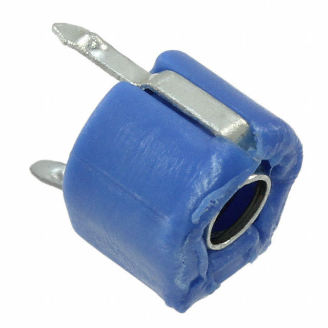
| 描述 | CAP TRIMMER 1-3PF 100V TH整流器/与可变电容器 1-3pF 100V 85 DEG |
| 产品分类 | |
| 品牌 | Sprague Goodman |
| 产品手册 | |
| 产品图片 | |
| rohs | RoHS 合规性豁免无铅 / 符合限制有害物质指令(RoHS)规范要求 |
| 产品系列 | 整流器/与可变电容器,Sprague Goodman GKG3R015SURFTRIM® GKG |
| 数据手册 | |
| 产品型号 | GKG3R015 |
| 产品 | Trimmer Capacitors - Ceramic Dielectric |
| 产品种类 | 整流器/与可变电容器 |
| 其它名称 | SG3R015 |
| 包装 | 散装 |
| 商标 | Sprague Goodman |
| 外壳长度 | 6 mm |
| 外壳高度 | 0.2 in |
| 大小/尺寸 | 圆形 - 0.236" 直径(6.00mm) |
| 安装类型 | 通孔 |
| 封装 | Bulk |
| 工作温度范围 | - 25 C to + 85 C |
| 工厂包装数量 | 100 |
| 引线间隔 | 0.24 in |
| 标准包装 | 500 |
| 温度系数/代码 | NP0 |
| 特性 | 通用 |
| 电压-额定 | 100V |
| 电压额定值 | 100 V |
| 电容范围 | 1 pF to 3 pF |
| 端接类型 | Snap In |
| 类型 | Ceramic Dielectric Trimmer Capacitor |
| 系列 | GKG |
| 调节类型 | 顶部调节 |
| 高度-安装(最大值) | 0.197"(5.00mm) |


- 商务部:美国ITC正式对集成电路等产品启动337调查
- 曝三星4nm工艺存在良率问题 高通将骁龙8 Gen1或转产台积电
- 太阳诱电将投资9.5亿元在常州建新厂生产MLCC 预计2023年完工
- 英特尔发布欧洲新工厂建设计划 深化IDM 2.0 战略
- 台积电先进制程称霸业界 有大客户加持明年业绩稳了
- 达到5530亿美元!SIA预计今年全球半导体销售额将创下新高
- 英特尔拟将自动驾驶子公司Mobileye上市 估值或超500亿美元
- 三星加码芯片和SET,合并消费电子和移动部门,撤换高东真等 CEO
- 三星电子宣布重大人事变动 还合并消费电子和移动部门
- 海关总署:前11个月进口集成电路产品价值2.52万亿元 增长14.8%


PDF Datasheet 数据手册内容提取
Sprague-Goodman ENGINEERING BULLETIN SG-305K.1 Supercedes SG-305J CERAMIC DIELECTRIC TRIMMER CAPACITORS Sprague-Goodman Electronics,Inc. 1700 SHAMES DRIVE, WESTBURY, NY 11590 TEL: 516-334-8700 • FAX: 516-334-8771 E-MAIL: info@spraguegoodman.com
CERAMIC DIELECTRIC TRIMMER CAPACITORS SG-305K SURFTRIM® SURFACE MOUNT GKRP SERIES FEATURES SPECIFICATIONS • Sealed for washability Operating Temperature Range: –40°C to +85°C • Low mounting profile. Voltage Rating: 25 VDC • Carrier and reel packaging standard. Dielectric Withstanding Voltage: 75 VDC • NPO temperature coefficient (up to 10 pF max). Insulation Resistance: 104 Megohms min • Self resonant frequency above 1 GHz. Torque: 10 to 150 g-cm (0.14 to 2.1 oz-in) 3.2 x 2.5 x 1.3mm Models Capacitance Carrier and (pF) TCC Q min Reel Pack min max (ppm/°C) (1 MHz) Model No. 3.0 5.0 0 ± 500 150 GKRP5R066 3.0 10.0 0 ± 500 150 GKRP10066 5.0 20.0 N750 ± 500 150 GKRP20066 7.0 30.0 N750 ± 500 150 GKRP30066 Carrier and reel specifications on page 11. 0.039 0.051 0.028 MAX 1.0 0.059 0.059 1.3 0.70 DIA 1.5 1.5 0.01 +0.006 0.091–0.002DIA 0.037 0.30 2.3 +0.15 0.95 –0.05 0.01 0.25 0.039 0.007 1.0 0.18 0.014 0.10 0.018TYP 0.35 0.13 2.5 0.45 3.2 0.075 1.9 0.039 1.0 0.035 0.9 PAD LAYOUT All dimensions are in /mm. Unless otherwise specified, the tolerance on dimensions is ±0.004/0.1. 2 SPRAGUE-GOODMAN ELECTRONICS, INC., 1700 SHAMES DRIVE,WESTBURY, NY 11590 • TEL: 516-334-8700 • FAX: 516-334-8771 • E-MAIL: info@spraguegoodman.com
CERAMIC DIELECTRIC TRIMMER CAPACITORS SG-305K.1 GKYB ECONOMY SERIES FEATURES SPECIFICATIONS • Suitable for reflow soldering. Operating Temperature Range: –25°C to +85°C • Superior Setting Drift Performance Voltage Rating: 100 VDC • Low Mounting Profile (only 1.7 mm) Dielectric Withstanding Voltage: 220 VDC • Available in carrier and reel packaging. Insulation Resistance: 104 Megohms min Torque: 25 to 100 g-cm (0.35 to 1.39 oz-in) 3.2 x 4.5 x 1.7mm Models Capacitance Range (pF) TCC Q min Color Code min max (ppm/°C) (1 MHz) or Mark Model No. 1.7 3.0 NP0 ±300 300 Brown GKYB3R066 2.5 6.0 NP0 ±300 500 Blue GKYB6R066 3.5 10.0 N750 ±300 500 White GKYB10066 5.5 20.0 N1200 ±500 300 Red GKYB20066 7.5 30.0 N1200 ±500 300 Green GKYB30066 Carrier and reel specifications on page 11. 0.029 01.0.24 7 00..07759 00.10.0.6613 2 ±± ± 0 00..0.100042 00.0.1056 ±± 00..00031 00..062 2.0 0.3 ± 0.06 STATOR 0.02 0.098 0.6 DIA 2.5 0.02 ± 0.002 0.5 ± 0.05 ROTOR 0.047 0.03 0.02 1.2 0.004 ± 0.002 0.8 0.6 0.18 0.13 0.10 ± 0.05 3.2 4.5 0.22 5.7 0.047 0.13 0.047 0.047 1.2 3.3 1.2 1.2 PAD LAYOUT All dimensions are in /mm. Unless otherwise specified, the tolerance on dimensions is ±0.04/0.1. SPRAGUE-GOODMAN ELECTRONICS, INC., 1700 SHAMES DRIVE,WESTBURY, NY 11590 • TEL: 516-334-8700 • FAX: 516-334-8771 • E-MAIL: info@spraguegoodman.com 3A
CERAMIC DIELECTRIC TRIMMER CAPACITORS SG-305K SURFTRIM® SURFACE MOUNT GKY WASHABLE SERIES 3.2 x 4.5 x 1.8mm FEATURES Models • Designed for reflow soldering. • Carrier and reel packaging. Capacitance Carrier and (pF) TCC Q min Reel Pack • Sealed for washability min max (ppm/°C) (1 MHz) Model No. 1.0 3.0 0 ± 500 300 GKY3R086 SPECIFICATIONS 2.5 10.0 0 ± 300 300 GKY10086 Operating Temperature Range: –40°C to +85°C 4.5 20.0 N750 ± 400 300 GKY20086 4.5 30.0 N750 ± 500 300 GKY30086 Voltage Rating: 25 VDC 4.5 40.0 N750 ± 500 300 GKY40086 Dielectric Withstanding Voltage: 75 VDC 4.5 50.0 N750 ± 500 300 GKY50086 Insulation Resistance: 104 Megohms min Carrier and reel specifications on page 11. Torque: 10 to 150 g-cm (0.14 to 2.08 oz-in) 0.071 0.043 MAX 0.02 1.1 0.067 1.8 00.0.1055 9 ± ± 00..00052 0.6 1.7 STATOR 0.071 +0 +0.006 1.8 TERMINALS 0.02 –0.004 03..102–+00..01052DIA ATOP PMROOUX.N FTLINUSGH 0.6 +–00.1 –0.05 SURFACE 0.02 TYP 0.5 0.059 ROTOR +0 0.04 1.5 0.031 0.02 –0.004 0.9 0.0047 ± 0.002 0.78 0.6 +0 0.18 03..123 0.018TYP 0.12 ± 0.05 –0.1 4.5 0.45 0.047 0.11 0.047 0.059 PAD LAYOUT 1.2 2.9 1.2 1.5 GGKKYY _ __ __ _8 686 GKY STANDARD SERIES FEATURES • Designed for reflow soldering. 3.2 x 4.5 x 1.8mm • Available in carrier and reel packaging. Models Capacitance Carrier and SPECIFICATIONS (pF) TCC Q min Color Bulk Pack Reel Pack Operating min max (ppm/°C) (1 MHz) Code Model No. Model No. Temperature Range: –25°C to +85°C 1.7 3.0 0 ± 300 500 Brown GKY3R000 GKY3R066 Voltage Rating: 100 VDC 2.5 6.0 0 ± 300 500 Blue GKY6R000 GKY6R066 3.0 10.0 N400 ± 400 500 White GKY10000 GKY10066 Dielectric Withstanding Voltage: 220 VDC 5.0 20.0 N900 ± 400 300 Red GKY20000 GKY20066 Insulation Resistance: 104 Megohms min 6.0 30.0 N1200 ± 500 300 Green GKY30000 GKY30066 Torque: 10 to 150 g-cm (0.14 to 2.08 oz-in) Carrier and reel specifications on page 11. 0.05 0.03 1.2 0.079 01.0.781 MAX 0.8 0.02 0.10.247 2.0 STATOR 0.6 0.075 1.9 04..158 03..102DIA TATEOPR PMMRIOONUXA.NL FSTLINUSGH 00..062 0.10.247 SURFACE 0.065 0.047 0.13 0.02 0.067 1.65 1.2 3.3 0.05 0.5 0.026 1.7 ROTOR 0.03 0.02 PAD LAYOUT 1.2 0.13 0.65 0.8 0.6 3.2 GKY _ _ _ 00, 66 All dimensions are in /mm. Unless otherwise specified, the tolerance on dimensions is ±0.004/0.1. 4 SPRAGUE-GOODMAN ELECTRONICS, INC., 1700 SHAMES DRIVE,WESTBURY, NY 11590 • TEL: 516-334-8700 • FAX: 516-334-8771 • E-MAIL: info@spraguegoodman.com
CERAMIC DIELECTRIC TRIMMER CAPACITORS SG-305K SURFTRIM® SURFACE MOUNT CONSTRUCTION DETAILS OF 4 x 4.5 mm GKG MODELS Model GKG__ __ __ 27Shown Sealed Construction • Special “drive assembly” with pointed spring fingers to engage rotor FEATURES upper surface contour. Spring fingers • Process seal provides protection against conta- also provide proper tension for smooth minants (flux, solvents, etc.) during production. torque and low resistance. • Special rotor with die-formed “drive” • Designed for flow and reflow soldering. contour on upper surface. • Available in carrier and reel packaging. • Flat-lapped and lubricated surfaces join for reliable capacitance settings. SPECIFICATIONS • Special ceramic stator insert Operating Temperature Range: –25°C to +85°C with metalized electrode. Voltage Rating: 100 VDC • Solid one-piece housing with integrally molded terminals and contact areas. Dielectric Withstanding Voltage: 220 VDC Central tubular column is spun-out Insulation Resistance: 104 Megohms min into a flare after assembly to maintain built-in spring tension. Torque: 15 to 100 g-cm (0.2 to 1.39 oz-in) 4 x 4.5 x 2.7mm Models Capacitance Carrier and Carrier and Carrier and (pF) TCC Q min Color Bulk Pack Reel Pack Bulk Pack Reel Pack Bulk Pack Reel Pack *min max (ppm/°C) (1 MHz) Code Model No. Model No. Model No. Model No. Model No. Model No. 1.4 3.0 0 ± 200 300** †Red Dot GKG3R026 GKG3R066 GKG3R027 GKG3R067 GKG3R028 GKG3R068 2.0 6.0 0 ± 200 500** Blue GKG6R026 GKG6R066 GKG6R027 GKG6R067 GKG6R028 GKG6R068 3.0 10.0 0 ± 300 500** White GKG10026 GKG10066 GKG10027 GKG10067 GKG10028 GKG10068 4.5 20.0 N900 ± 300 500** Red GKG20026 GKG20066 GKG20027 GKG20067 GKG20028 GKG20068 6.5 30.0 N1100 ±450 300 Green GKG30026 GKG30066 GKG30027 GKG30067 GKG30028 GKG30068 15.0 50.0 N1700 ±500 300 Orange GKG50H26 GKG50H66 GKG50H27 GKG50H67 GKG50H28 GKG50H68 † Marking on bottom of capacitor. Available without seal — consult factory. * Re-rated in 1994 for lower min capacitance. Carrier and reel specifications on page 11. ** Q at 10 MHz Add –07 to Model No. for 700/reel, –25 for 2500/reel. 0.16 ± 0.008 0.16 ± 0.008 TERMINALS 4.0 ± 0.2 0.11 ± 0.008 4.0 ± 0.2 0.11 ± 0.008 APPROX. FLUSH TO 2.7 ± 0.2 0.02 0.02 2.7 ± 0.2 ROTOR MOUNTING SURFACE SLOTS0.02x0.02DP ROTOR SLOTS x DP 0.5 0.5 0.5 0.5 TERMINALS 0.094 0.18 ± 0.008 0.11 ± 0.008 0.094 0.18 ± 0.008 ATOP PMROOUX.N FTLINUGSH 2.4 4.5 ± 0.2 2.8 ± 0.2 2.4 4.5 ± 0.2 SURFACE 01.0.455DIA 01.0.247TYP SEASLTATOR 05..220max 01.0.455DIA 0.047 SEAL ST0A.T2O8 R± 0.008 TYP 1.2 7.0 ± 0.2 GKG _ _ _ 26,66 GKG _ _ _ 27,67 0.16 ± 0.008 TERMINALS 0.11 ± 0.008 0.094 0.079TYP PAD LAYOUTS 4.0 ± 0.2 MOAUPNPRTIONXG. FSLUURSFHA CTOE 2.9 ± 0.2 2.4 2.0 ROTOR SLOTS 0 0 ..052x00..052DP SEAL 0.063 04..106 02.0.079TYP GKG _ _ _ 26,66 1.6 0.094 0.18 ± 0.008 0.28 ± 0.02 2.4 4.5 ± 0.2 7.0 ± 0.5 0.063 0.16 0.079 0.055DIA 4.0 2.0 TYP 1.6 1.4 STATOR 0 . 31.2005 ± ± 00..01056 D IA 0.047 1.2 TYP GKG _ _ _ 28,68 0.063 GKG _ _ _ 28,68 GKG _ _ _ 27,67 1.6 All dimensions are in/mm. Unless otherwise specified, the tolerance on dimensions is ±0.004/0.1. SPRAGUE-GOODMAN ELECTRONICS, INC., 1700 SHAMES DRIVE,WESTBURY, NY 11590 • TEL: 516-334-8700 • FAX: 516-334-8771 • E-MAIL: info@spraguegoodman.com 5
CERAMIC DIELECTRIC TRIMMER CAPACITORS SG-305K PLASTIC ENCASED TYPE Available With or Without Adjust Cavity Seal FEATURES SPECIFICATIONS • Very low cost due to automated production and Operating Temperature Range: –25°C to +85°C solderless touch contact construction. Voltage Rating: 100 VDC • Wide selection of capacitance ranges. Dielectric Withstanding Voltage: 220 VDC • Color coded housings. Insulation Resistance: 104 Megohms min • Easy blind tuning (2 slots at 90° angle in adjust Torque: 10 to 100 g-cm (0.14 to 1.39 oz-in) cavity — accepts cross-slotted tool). • Process seal on adjust screw access face (optional) provides protection against contaminants (flux, cleaning agents, etc.) during production. 4 x 4.5mm Models Capacitance Top Mount3 Top Mount3 Top Mount4 (pF) TCC Q min Color Spring Lead Model No. Spring Lead Model No. Ammo Pack Model No. 1min max (ppm/°C) 1 MHz 10 MHz Code Unsealed Sealed Unsealed Sealed Unsealed 1.4 3.0 0 ± 200 300 300 2Red Dot GKG3R021 GKG3R071 GKG3R024 GKG3R074 GKG3R025 2.0 6.0 0 ± 200 500 300 Blue GKG6R021 GKG6R071 GKG6R024 GKG6R074 GKG6R025 3.0 10.0 0 ± 300 500 300 White GKG10021 GKG10071 GKG10024 GKG10074 GKG10025 4.5 20.0 N900 ± 350 500 300 Red GKG20021 GKG20071 GKG20024 GKG20074 GKG20025 6.5 30.0 N1100 ± 450 300 300 Green GKG30021 GKG30071 GKG30024 GKG30074 GKG30025 15.0 50.0 N1700 ± 500 300 N.A. Orange GKG50021 GKG50071 GKG50024 GKG50074 GKG50025 1Re-rated in 1993. 3Magazine pack (120 pieces) for auto insertion available — consult 2Marking on bottom of capacitor. factory for pricing. 4Ammo pack contains 1000 pcs. SLOTS00..052x00..052DP 00.3.11.143 ± ±± 0 00.0..50028 0.16 ± 0.008 0.094 ± 0.02 06.2.24 ±± 00..502 0.079 ± 0.008 2.7 ± 0.2 4.0 ± 0.2 2.4 ± 0.5 2.0 ± 0.2 0.094 ± 0.02 SLOTS 0.11 ± 0.008 2.4 ± 0.5 0.02x0.02DP 2.7 ± 0.2 ROTOR 0.5 0.5 ROTOR 0.008 ± 0.002TYP 0.18 ± 0.008 0.094 0.148 ± .01 0.21 ± 0.02 0.094 0.18 ± 0.008 0.2 ± 0.05 4.5 ± 0.2 2.4 3.75 ± 0.3 5.3 ± 0.5 2.4 4.5 ± 0.2 01.0.455DIA STATOR 0.008 ± 0.002TYP 01.0.455DIA STATOR 0.41.60 ±± 00..0208 0.2 ± 0.05 01.0.039D(2I AHOLES) 00..073 030..11.704.50389D(2I AH OLES) 00..073 0.016.63 ±± 00..2008 Mounting Hole0 5L.a.200yout 0.10.52 ±± 00..0104 TYP Mounting Hole Layout GKG _ _ _ 21, 71 GKG _ _ _ 24, 74 0.500 ± 0.04 12.7 ± 1 0.16 ± 0.008 4.0 ± 0.2 0.027.09 ±± 00..2008 A 0.R21O.17 T ±O± 0R0..02A08 01.0.559+–+–0000..0520 04.1.06 ±± 00..2008DIA 0.650+–00.06 16.5+1.5 0.094 0.18 ± 0.008 0.35 ± 0.02 –0 2.4 4.5 ± 0.2 0.2 min 9.0 ± 0.5 5.0 01.0.455DIA 0.016.63 ±± 00..2008 STATOR 0 .1781+–+–0001...05024 SLOTS 0.02x0.02DP 0.5 0.5 0.047 0.06max 0.152 ± 0.03 0.024 ± 0.01 1.2 VIEW A-A 1.5 3.85 ± 0.8 0.60 ± 0.3 (ROTOR) 0.2 ± 0.002 0.500 ± 0.01 0.02 ± 0.002DIA 5.0 ± 0.05 12.7 ± 0.3 0.5 ± 0.05 GKG _ _ _ 25 GKG _ _ _ 25 TAPE DIMENSIONS All dimensions are in /mm.Unless otherwise specified, the tolerance on dimensions is ±0.004/0.1. 6 SPRAGUE-GOODMAN ELECTRONICS, INC., 1700 SHAMES DRIVE,WESTBURY, NY 11590 • TEL: 516-334-8700 • FAX: 516-334-8771 • E-MAIL: info@spraguegoodman.com
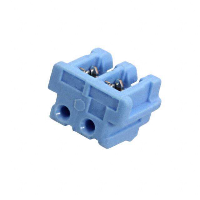
CERAMIC DIELECTRIC TRIMMER CAPACITORS SG-305K PLASTIC ENCASED TYPE GKG SERIES FEATURES SPECIFICATIONS • Very low cost. Operating Temperature Range: –25°C to +85°C • Wide selection of capacitance ranges. Voltage Rating: 100 VDC • Suitable for printed circuit production methods Dielectric Withstanding Voltage: 220 VDC using “spring leads”or “straight leads”. Insulation Resistance: 104 Megohms min Torque: 15 to 150 g-cm (0.21 to 2.1 oz-in) 6mm Economy Models Capacitance (pF) Top Adjust Bottom Adjust min max TCC (ppm/°C) Q min (1 MHz) Color Code Model No. Model No. 1.0 3.0 NPO ± 250 300 Black GKG3R015 GKG3R016 2.0 5.0 NPO ± 250 300 Blue GKG5R015 GKG5R016 3.0 10.0 NPO ± 250 300 White GKG10015 GKG10016 5.0 20.0 N750 ± 250 300 Red GKG20015 GKG20016 6.5 30.0 N1000 ± 500 200 Green GKG30015 GKG30016 7.0 40.0 N2200 ± 800 200 Yellow GKG40015 GKG40016 10.0 50.0 N2200 ± 800 200 Brown GKG50015 GKG50016 12.0 60.0 N2200 ± 800 200 Brown GKG60015 GKG60016 15.0 70.0 N2200 ± 800 200 Brown GKG70015 GKG70016 18.0 90.0 N2200 ± 800 150 Brown GKG90015 GKG90016 06.2.04 ±± 0 .00.028 04.1.06 ±± 0 .00.028 05..20 06.2.04 ±± 0 .00.028 04.1.06 ±± 0 .00.028 03..133 05..20 0.24 ± 0.008DIA 0.24 ± 0.008DIA 6.0 ± 0.2 6.0 ± 0.2 0.04 ± 0.002TYP 1.0 ± 0.05 02.0.59 8 ±± 0 .00.028DIA 00.0.62 ±± 0 .00.028X 0 0 . .0 5 2 DP 01..004 ±± 00..00052TYP 0.098 ± 0.008DIA 00.0.62 ±± 0 .00.028X 0 0 . .0 5 2 DP 2.5 ± 0.2 ~ COLOR CODE 01.0.247DIA (2 PLCS) 0.047DIA 03..102DIA 03..133 01.0.559 00.0.20598 00.0.208 (12. 2PLCS) 0.20 0.25 ROTOR STATOR 5.0 6.3 Mounting Hole Layout ROTOR STATOR Mounting Hole Layout 0.0098 0.008 COLOR CODE 0.25 0.2 ~ 0.24 ± 0.008 6.0 ± 0.2 GKG _ _ _ 15 GKG _ _ _ 16 All dimensions are in /mm. Unless otherwise specified, the tolerance on dimensions is ±0.004/0.1; except slot tolerance is ±0.008/0.2. SPRAGUE-GOODMAN ELECTRONICS, INC., 1700 SHAMES DRIVE,WESTBURY, NY 11590 • TEL: 516-334-8700 • FAX: 516-334-8771 • E-MAIL: info@spraguegoodman.com 7
CERAMIC DIELECTRIC TRIMMER CAPACITORS SG-305K RUGGED 5 mm GKU SERIES FEATURES • Proven rugged axle design prevents electrode shifting, maximizes stability. • Plastic washer between adjust shaft and ceramic rotor to absorb tuning and environmental stresses. • Special ceramic dielectric rotor with metalized electrode. • Flat-lapped and lubricated surfaces join for reliable capacity settings. • Solid one-piece stator electrode and terminal, recessed and integral with base. Cannot shift. Improves stability and resistance to humidity. • Combination spring/contact/terminal maintains proper tension for smooth torque and low resis- tance. • Soldered connection between adjust shaft and rotor electrode eliminates contact resistance problems. • Compact form factor conserves mounting space. • Straight line capacitance curve. • Low cost for industrial and commercial applications. SPECIFICATIONS Operating Temperature Range: –55°C to +125°C Voltage Rating: 250 VDC at 85°C 125 VDC at 125°C Dielectric Withstanding Voltage: 500 VDC at 85°C 250 VDC at 125°C Insulation Resistance: 104 Megohms min Torque: 30 to 140 g-cm (0.42 to 1.94 oz-in) 0.039 1.0 0.20 5.2 5mm Rugged Models 0.13 CRaapnagceit a(pnFc)e TCC Q min Color Code 3.4 05..283 05..252max 0.31.20 ±± 00..052 min max (ppm/°C) (10 MHz) or Mark Model No. 1.5 † 5.5 0 ± 250 300 Black GKU4R000 SLOT 0.02x0.02DP 0.5 0.5 0.20 2.0 † 8.0 N100 ± 200 300 Red GKU6R000 5.0 0.051DIA 2.8 † 12.0 N600 ± 300 300 None GKU10000 1.3 (2 HOLES) 3.3 †† 20.5 N800 ± 300 300 Blue GKU18000 3.8 † 28.5 N1350 ± 650 200 Purple GKU25000 4.5 30.0 N1350 ± 650 200 Orange GKU30000 STATOR ROTOR Mounting Hole Layout 5.0 40.0 N1600 ± 800 200 Brown GKU40000 6.0 50.0 N1300 ± 500 150 (1MHz) Green GKU50000 0.010 0.006 0.25 0.15 7.0 60.0 N1300 ± 500 150 (1MHz) Pink GKU60000 15.0 90.0 N1500 ± 800 100 (1MHz) None GKU90000 GKU _ _ _ 00 † Re-rated in 1992 †† Re-rated in 1986 All dimensions are in /mm. Unless otherwise specified, the tolerance on dimensions is ±0.004/0.1. 8 SPRAGUE-GOODMAN ELECTRONICS, INC., 1700 SHAMES DRIVE,WESTBURY, NY 11590 • TEL: 516-334-8700 • FAX: 516-334-8771 • E-MAIL: info@spraguegoodman.com
CERAMIC DIELECTRIC TRIMMER CAPACITORS SG-305K ECONOMY 5 mm GKU SERIES FEATURES SPECIFICATIONS • Economical for consumer and industrial applications. Operating Temperature Range: –25°C to +85°C • Rotor soldered to tuning axle for stability. Voltage Rating: 250 VDC • For lead-through-hole connection to printed circuit Dielectric Withstanding Voltages: 500 VDC boards. Insulation Resistance: 104 Megohms min Torque: 35 to 200 g-cm (0.49 to 2.8 oz-in) 0.039 ± 0.002TYP 1.0 ± 0.05 0.20 5.0 5mm Economy Models Capacitance 05..283TYP 03..102TYP Range (pF) SLOT 0.02x0.02DP min max TCC(ppm/°C) Q min(1 MHz) Model No. 0.5 0.5 1.0 3.0 0 ± 250 300 GKU3R010 0.23 ± 0.008 2.0 6.0 0 ± 250 300 GKU6R010 5.8 ± 0.2 3.0 10.0 N750 ± 250 300 GKU10010 0.010TYP 4.8 20.0 N750 ± 250 300 GKU20010 0.25 0.047 DIA 2 PLCS 5.5 30.0 N1000 ± 250 200 GKU30010 1.2 STATOR ROTOR Mounting Hole Layout 6.8 40.0 N2200 ± 800 200 GKU40010 0.12 0.10 9.8 50.0 N2200 ± 800 200 GKU50010 3.0 2.6 12.0 60.0 N2200 ± 800 200 GKU60010 GKU _ _ _ 10 14.0 70.0 N2200 ± 800 200 GKU70010 ECONOMY 7mm GKT SERIES FEATURES SPECIFICATIONS • Economical for consumer and industrial applications. Operating Temperature Range: –25°C to +85°C • Rotor soldered to tuning axle for stability. Voltage Rating: 250 VDC • For lead-through-hole connection to printed circuit Dielectric Withstanding Voltages: 500 VDC boards. Insulation Resistance: 104 Megohms min • Three hole mounting pattern. Torque: 32 to 200 g-cm (0.45 to 2.8 oz-in) 0.28 0.26 0.15 7.0 6.5 3.8 0.04 1.0 SLOT 0.335 0.02x0.02DP 8.5 0.6 0.6 7mm Economy Models SOLDER 0.20 ± 0.008 CRaapnagceit a(pnFc)e 03.1.02DIA 00..02150TYP 5.0 ± 0.2 min max TCC(ppm/°C) Q min(1 MHz) Model No. 2.0 5.0 0 ± 200 300 GKT5R012 01.400.49 07.2.08 ±± 0 .00.028 (30 P.10.L42C7SD)IA 2.5 10.0 0 ± 200 300 GKT10012 ROTOR 3.0 20.0 N470 ± 200 300 GKT20012 (2 PLCS) 4.5 30.0 N550 ± 800 300 GKT30012 0.010 6.0 50.0 N1400 ± 800 200 GKT50012 0.040 0.25 180..55 6831..00 NN22220000 ±± 225500 220000 GGKKTT6800001122 1.0 STATOR 0.28 ± 0.008 Mounting Hole Layout05.2.00 ±± 0 .00.028 7.0 ± 0.2 12.0 90.0 N2200 ± 250 200 GKT90012 GKT _ _ _ 12 All dimensions are in /mm. Unless otherwise specified, the tolerance on dimensions is ±0.004/0.1. SPRAGUE-GOODMAN ELECTRONICS, INC., 1700 SHAMES DRIVE,WESTBURY, NY 11590 • TEL: 516-334-8700 • FAX: 516-334-8771 • E-MAIL: info@spraguegoodman.com 9
CERAMIC DIELECTRIC TRIMMER CAPACITORS SG-305K THIN 2 mm & 3mm TYPES FEATURES SPECIFICATIONS • Very small size — for hybrid circuit applications. Operating Temperature Range: –25°C to +85°C • Straight line capacitance curve. Voltage Rating: 25 VDC • Choice of mounting styles. Dielectric Withstanding Voltages: 75 VDC Insulation Resistance: 104 Megohms min Torque: 10 to 75 g-cm (0.14 to 1.0 oz-in) Terminal Plating: Silver 0.19 4.8 0.03 0.8 0.03 0.7 0.091 DIA max 2.3 STATOR ROTOR SLOT0.012x0.007DP MINIATURE SERIES 0.25 0.18 2.0 x 1.2mm Models 0.047max 0.005TYP 1.2 0.12 Capacitance (pF) min* max TCC (ppm/°C) Q min (1 MHz) Model No. 5.0 25.0 N1200 ±800 100 GKH25000 GKH _ _ _ 00 *Re-rated in 1996 3.0 x 1.8mm Models Capacitance (pF) min max TCC (ppm/°C) Q min (1 MHz) Model No. Model No. 1.0 3.0 0 ± 300 200 GKX3R010 GKX3R011 1.5 5.0 0 ± 300 200 GKX5R010 GKX5R011 2.5 10.0 0 ± 300 200 GKX10010 GKX10011 5.0 20.0 N750 ± 500 200 GKX20010 GKX20011 5.0 30.0 N750 ± 500 200 GKX30010 GKX30011 5.0 35.0 N750 ± 500 200 GKX35010 GKX35011 6.0 40.0 N750 ± 500 200 GKX40010 GKX40011 0.33 0.079 8.5 2.0 DIA 0.079 0.03 2.0 TYP 0.8 DIA 0.02 0.014 SLOT0.5 x 0.35 DP 0.12 ± 0.01DIA 0.03TYP 3.0 ± 0.2 0.8 SLOT00..052 x 0 0.0.3154 DP 03..102 ±± 0 0.0.21DIA 01.0.039DTYIAP 0.2 ± 0.02 5.0 ± 0 .5 0.071 max 0.006 1.8 0.144 ± 0.02TYP MOUNTING HOLE LAYOUT 0.15 ROTOR 0.071max 3.65 ± 0.5 1.8 STATOR 0.005 00..01056 0.005 0.12 0.2 ± 0.02 0.12 5.0 ± 0.5 GKX _ _ _ 10 GKX _ _ _ 11 All dimensions are in /mm. Unless otherwise specified, the tolerance on dimensions is ±0.004/0.1. 10 SPRAGUE-GOODMAN ELECTRONICS, INC., 1700 SHAMES DRIVE,WESTBURY, NY 11590 • TEL: 516-334-8700 • FAX: 516-334-8771 • E-MAIL: info@spraguegoodman.com
CERAMIC DIELECTRIC TRIMMER CAPACITORS SG-305K CARRIER AND REEL SPECIFICATIONS CARRIER Dimension A B C D E F G H K L M N P LPirnoeduct Tolerance ±0––.0–0.–01––4 ±0—.00–.—014- ±0—0..0—31 ±0—.00–.—014- ±0—.00–.—014- ±0—.00–.—014- ±0—.00—.01–4- ±0—.00—.01–4- ±0—.00–.—028- ±0—0..0—005–2- +–0—.000–.—014- ±0—0.0–.—014- ±0—.00—.01–4- 0.18 0.21 0.47 0.22 0.069 0.31 0.08 0.2 0.13 0.01 0.059 GKG_ _ _ 66 Fig. 2 —— —— —— —— —–—- —– —— —— —— —— —— –– –– 4.5 5.4 12 5.5 1.75 8.0 2.0 4 3.2 0.3 1.5 0.18 0.30 0.47 0.22 0.069 0.31 0.08 0.2 0.13 0.01 0.059 0.08 0.2 GKG_ _ _ 67, 68 Fig. 1 –––––– —— —–— —–—- —–—- —–—- —— —–- —–—- ——–- —–—- —–— —–— 4.5 7.5 12 5.5 1.75 8.0 2.0 4 3.2 0.3 1.5 2.0 5 0.11 0.13 0.47 0.22 0.069 0.16 0.08 0.2 0.075 0.01 0.059 GKRP_ _ _ 66 Fig. 2 —— —— —— —— —–—- —– —— —- —–—- —— —–—- –– –– 2.7 3.2 12 5.5 1.75 4.0 2.0 4 1.9 0.3 1.5 0.14 0.19 0.47 0.22 0.069 0.31 0.08 0.2 0.091 0.01 0.059 GKY_ _ _ 66, GKYA Fig. 2 —— —— —— —— —–—- —– —— —- —–—- —— —–—- –– –– 3.6 4.9 12 5.5 1.75 8.0 2.0 4 2.3 0.3 1.5 0.132 0.185 0.47 0.22 0.069 0.31 0.08 0.2 0.091 0.01 0.059 GKY_ _ _ 86 Fig. 2 –––––– —–—- —–— —–—- —–—- —–—- ——–- ——–- —–—- ——–- —–—- –– –– 3.35 4.70 12 5.5 1.75 8.0 2.0 4 2.4 0.3 1.5 All dimensions are in/ mm. Unless otherwise specified, the tolerance on dimensions is ±0.004 / 0.1. GKG and GKY_ _ _66 series capacitors are positioned in compartments (blisters) with the stator terminal closer to the "M" holes. To get the parts with the rotor terminal closer to the "M" holes, add an "A" suffix to the model number. GKRP and GKY_ _ _86 series capacitors are positioned in compartments (blisters) with the rotor terminal closer to the "M" holes. To get the parts with the stator terminal closer to the "M" holes, add an "A" suffix to the model number. E G H M DIA E G H M DIA L COVER TAPE C D C D 0.003 THK P B B 0.075 N K FIG. 1 F FIG. 2 F A END VIEW A 03..102TYP 03..102TYP Embossment Details 0.14 0.14 3.6 3.6 00..083TYP 00..083TYP GKG _ _ _ 67,68 GKG _ _ _ 66 REEL Dimension Quantity A B C D E T W Per Product Tolerance Reel ±–0–.–1– ±—0.—1 ±0—.0—4 ±—0.—08- ±—0.—04- ±—0.—02- ±0—.0—8 E Line 3 3 1 2 1 0.5 2 C 7.09 2.4 0.51 0.91 0.08 0.043 0.531 GKG_ _ _ 66-07, 67-07, 700 ——- –— ——- ——- ——- —–—- —–––— 68-07 180 60 13 23 2 1.1 13.5 13.0 3.1 0.51 0.91 0.098 0.079 0.531 GKG_ _ _ 66-25, 67-25, 2500 ——- –— —–—- —–—- —–—- —–—- —–––— B 68-25 330 80 13 23 2.5 2.0 13.5 7.09 2.4 0.51 0.83 0.08 0.047 0.512 GKRP_ _ _ 66 2000 ——- –— ——- ——- ——- ——- —––— 180 60 13 21 2 1.2 13.0 D 7.09 2.4 0.51 0.91 0.08 0.043 0.531 GKY_ _ _ 66, GKYA 1000 ——- –— ——- ——- ——- ——- —–– 180 60 13 23 2 1.1 13.5 A T 7.09 2.4 0.51 0.83 0.08 0.047 0.512 W GKY_ _ _ 86 1000 ——- –— ——- ——- ——- ——- —––— 180 60 13 21 2 1.2 13.0 All dimensions are in/mm. Unless otherwise specified, the tolerance on dimensions is ±0.004/0.1. SPRAGUE-GOODMAN ELECTRONICS, INC., 1700 SHAMES DRIVE,WESTBURY, NY 11590 • TEL: 516-334-8700 • FAX: 516-334-8771 • E-MAIL: info@spraguegoodman.com 11
CERAMIC DIELECTRIC TRIMMER CAPACITORS SG-305K SPECIFICATION NOTES APPLICATION NOTES Soldering and Cleaning 1.Parts are 100% tested for capacitance range, dielectric withstanding voltage, insulation resis- of Ceramic Trimmer Capacitors tance, and torque. Soldering temperatures and times are specified in 2.Capacitance range specified is that which is guar- Notes 3 and 4 above. If using an iron for manual sol- anteed, and is measured at 1 MHz and 25°C. dering (for prototyping or repairs, for example) use an appropriate size and temperature so that the 3.For soldering SURFTRIM®surface mounting models, high temperature exposure of the trimmer is less pre-heat at 140°C ±10°C for 2 minutes maximum, than 3 seconds. and reflow solder at 240°C ±5°C for 20 seconds maximum. We strongly recommend the use of water soluble fluxes for soldering, followed by cleaning in water 4.For soldering printed circuit board mounting mod- containing detergents, and then a clear water els, solder at 260°C ±10°C for 5 seconds maximum, rinse. except 3 seconds maximum for Miniature Models (page 10). Some operations still use Freon or similar fluorinated or chlorinated hydrocarbon solvents. These solvents 5.Q factor is measured at maximum rated capaci- have a tendency to remove the lubricant, which in tance and at room temperature. Frequency of turn makes for bumpy adjustment, and will degrade measurement is as listed for each model. the tuning torque, adjustment life, and other 6.Dielectric strength is measured at maximum rated mechanical specifications. capacitance and room temperature, with test volt- In general, the minimum exposure to cleaning solu- age as listed for each model applied for 5 seconds. tions is recommended. The gentlest would be the 7.Insulation resistance is measured at maximum rated detergent and water rinses at fairly low tempera- capacitance and room temperature and at rated tures. When chlorinated or fluorinated hydrocarbons voltage, unless otherwise specified. are used, the boards should never be plunged into the solvent solution, but rather maintained in the 8.Temperature coefficient of capacitance (TCC) is vapor area of the defluxing equipment, and for the measured at 100 kHz or 1 MHz, over a temperature minimum possible time. Most desirable would be to range of –20°C to +70°C with capacitor set at maxi- clean only the bottom of the printed circuit board, mum rated capacitance. as with board scrubbers. 9.Axial load during tuning should not exceed 250 The unsealed GKG models are usually specified for grams. consumer applications where cleaning after soldering 10.Capacitors should not be operated outside of is normally not required. Should cleaning be required, rated capacitance range and working voltage. the method to use would be to clean the bottom of the board, as with board scrubbers. If a solvent is used 11.Angular orientation of adjusting slot is random. when cleaning the GKG series, sealed versions should be specified to prevent the solvent from being trapped in the housing and degrading performance. Other precautions for using ceramic trimmer capaci- tors include: • Beware of excessive handling with bare hands as, “finger oil” and dirt can bring down Q and insulation resistance values. • Terminals should not be cut or reformed, as this could cause deformation of the spring or break- ing of the rotor. Sprague-Goodman Electronics, Inc. 1700 SHAMES DRIVE, WESTBURY, NY 11590 TEL: 516-334-8700 • FAX: 516-334-8771 E-MAIL: info@spraguegoodman.com WEBSITE: http://www.spraguegoodman.com © 2005 SPRAGUE-GOODMAN ELECTRONICS, INC., ALL RIGHTS RESERVED. PRINTED IN THE U.S.A. 2.50501