ICGOO在线商城 > 继电器 > 高频 (RF) 继电器 > G6Z-1FE-A DC12

 Datasheet下载
- 型号: G6Z-1FE-A DC12
- 制造商: Omron Electronics LLC
- 库位|库存: xxxx|xxxx
- 要求:
| 数量阶梯 | 香港交货 | 国内含税 |
| +xxxx | $xxxx | ¥xxxx |
查看当月历史价格
查看今年历史价格
G6Z-1FE-A DC12产品简介:
ICGOO电子元器件商城为您提供G6Z-1FE-A DC12由Omron Electronics LLC设计生产,在icgoo商城现货销售,并且可以通过原厂、代理商等渠道进行代购。 G6Z-1FE-A DC12价格参考。Omron Electronics LLCG6Z-1FE-A DC12封装/规格:高频 (RF) 继电器, 。您可以下载G6Z-1FE-A DC12参考资料、Datasheet数据手册功能说明书,资料中有G6Z-1FE-A DC12 详细功能的应用电路图电压和使用方法及教程。
| 参数 | 数值 |
| 产品目录 | |
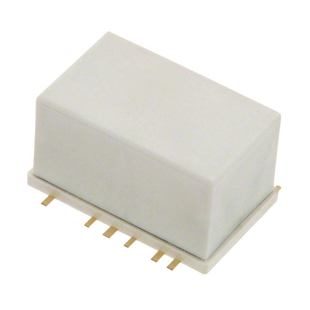
| 描述 | RELAY RF SPDT 10MA 12V |
| 产品分类 | |
| 品牌 | Omron Electronics Inc-EMC Div |
| 数据手册 | |
| 产品图片 |
|
| 产品型号 | G6Z-1FE-A DC12 |
| PCN过时产品 | |
| rohs | 无铅 / 符合限制有害物质指令(RoHS)规范要求 |
| 产品系列 | G6Z |
| 关闭电压(最小值) | 1.2 VDC |
| 其它名称 | G6Z 8020A |
| 其它有关文件 | |
| 包装 | 管件 |
| 安装类型 | 表面贴装 |
| 导通电压(最大值) | 9 VDC |
| 工作时间 | 10ms |
| 工作温度 | -40°C ~ 70°C |
| 开关电压 | 30VAC,30VDC - 最小值 |
| 标准包装 | 50 |
| 特性 | 密封式 - 全部 |
| 端子类型 | 鸥翼型 |
| 线圈功率 | 200 mW |
| 线圈电压 | 12VDC |
| 线圈电流 | 16.7mA |
| 线圈电阻 | 720 欧姆 |
| 线圈类型 | 无锁存 |
| 继电器类型 | RF |
| 触头外形 | SPDT(1 C 型) |
| 触头材料 | 铜(Cu),金(Au) |
| 释放时间 | 10ms |
| 额定接触(电流) | 10mA |


- 商务部:美国ITC正式对集成电路等产品启动337调查
- 曝三星4nm工艺存在良率问题 高通将骁龙8 Gen1或转产台积电
- 太阳诱电将投资9.5亿元在常州建新厂生产MLCC 预计2023年完工
- 英特尔发布欧洲新工厂建设计划 深化IDM 2.0 战略
- 台积电先进制程称霸业界 有大客户加持明年业绩稳了
- 达到5530亿美元!SIA预计今年全球半导体销售额将创下新高
- 英特尔拟将自动驾驶子公司Mobileye上市 估值或超500亿美元
- 三星加码芯片和SET,合并消费电子和移动部门,撤换高东真等 CEO
- 三星电子宣布重大人事变动 还合并消费电子和移动部门
- 海关总署:前11个月进口集成电路产品价值2.52万亿元 增长14.8%
PDF Datasheet 数据手册内容提取
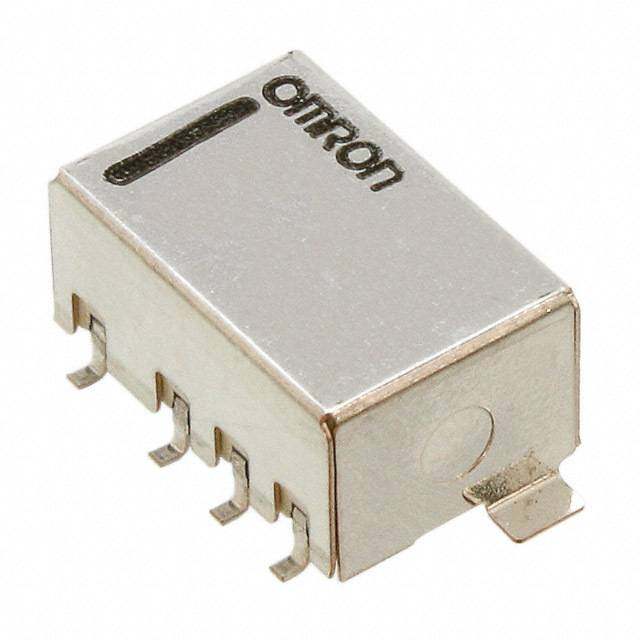
G6Z Surface-mounting High-frequency Relay Surface-mounting, 3-GHz-Band, Miniature, SPDT, High-frequency Relay •Superior high-frequency characteristics, such as an isolation of 30 dB min., insertion loss of 0.5 dB max., and V.SWR of 1.5 max. at 2.6 GHz. (cid:129)Surface-mounting terminals and superior high frequency characteristics combined using semi triplate strip transmission lines. (cid:129)Miniature dimensions of 20 × 8.6 × 8.9 mm (L × W × H). (cid:129)Choose from a lineup that includes single-winding latching models (200 mW), double-winding latching models (360 mW), and models with a reverse contact arrangement. (cid:129)Series includes models with an E-shape terminal structure (same as existing models), and models with a Y-shape terminal structure, allowing greater freedom with PCB design. (cid:129)Models with 75-Ω impedance and models with 50-Ω impedance are available. RoHS Compliant G ■Model Number Legend ■Application Examples 6 Z G6Z@-@@@-@@ These Relays can be used for switching signals in media — — — — — — equipment. 1 2 3 4 5 6 (cid:129)Wire communications: Cable TV (STB and broadcasting 1. Relay Function 4. Terminal arrangement infrastructure), cable modems, and None:Single-side stable None:Y-shape terminal VRS (video response systems) U: Single-winding structure (cid:129)Wireless communications:Transceivers, ham radios, car latching E: E-shape terminal telephones, ETC, ITS, high-level K: Double-winding structure TV, satellite broadcasting, text latching multiplex broadcasting, pay TV, 5. Characteristic Impedance mobile phone stations, TV 2. Contact Form None:75 Ω broadcasting facilities, and 1: SPDT (1c) A: 50 Ω community antenna systems 3. Terminal Shape 6. Contact Arrangement (cid:129)Public equipment: TVs, TV games, satellite radio units, F: Surface-mounting None:Standard contact car navigation systems terminals arrangement (cid:129)Industrial equipment: Measuring equipment, test P: PCB terminals R: Reverse contact equipment, and multiplex arrangement transmission devices ■Ordering Information ●Standard Models with PCB Terminals Enclosure Contact Terminal Characteristic Minmum packing Relay Function Model Rated coil voltage rating form arrangement impedance unit 75 Ω G6Z-1PE 3, 4.5, 5, 9, 12, 24 VDC E-shape 50 Ω G6Z-1PE-A 3, 4.5, 5, 9, 12, 24 VDC Singleside stable 75 Ω G6Z-1P 3, 4.5, 5, 9, 12, 24 VDC Y-shape 50 Ω G6Z-1P-A 3, 4.5, 5, 9, 12, 24 VDC 75 Ω G6ZU-1PE E-shape Singlewinding SPDT 50 Ω G6ZU-1PE-A Fully sealed 3, 4.5, 5, 9, 12, 24 VDC 25 pcs/tube latching (1c) 75 Ω G6ZU-1P Y-shape 50 Ω G6ZU-1P-A 75 Ω G6ZK-1PE E-shape Doublewinding 50 Ω G6ZK-1PE-A 3, 4.5, 5, 9, 12, 24 VDC latching 75 Ω G6ZK-1P Y-shape 50 Ω G6ZK-1P-A Note. Please add the coil rated voltage (V) to the model number when ordering. Example: G6Z-1PE DC3 In addition, the delivered product and its package will be marked with voltage specification as "@@VDC". 1
G6Z Surface-mounting High-frequency Relay ●Standard Models with Surface-mounting Terminals Minimum Enclosure Contact Terminal Characteristic Rated coil Minmum Relay Function Model ordering unit rating form arrangement impedance voltage packing unit (Tape packing) 75 Ω G6Z-1FE E-shape 50 Ω G6Z-1FE-A 3, 4.5, 5, 9, 12 Singleside stable 75 Ω G6Z-1F and 24 VDC Y-shape 50 Ω G6Z-1F-A 75 Ω G6ZU-1FE E-shape Singlewinding SPDT 50 Ω G6ZU-1FE-A 3, 4.5, 5, 9, 12 25 pcs/tube Fully sealed (300 pcs/ 300 pcs/reel latching (1c) 75 Ω G6ZU-1F and 24 VDC reel) Y-shape 50 Ω G6ZU-1F-A 75 Ω G6ZK-1FE E-shape Doublewinding 50 Ω G6ZK-1FE-A 3, 4.5, 5, 9, 12 latching 75 Ω G6ZK-1F and 24 VDC Y-shape 50 Ω G6ZK-1F-A Note 1.Please add the coil rated voltage (V) to the model number when ordering. Example: G6Z-1PE DC3 In addition, the delivered product and its package will be marked with voltage specification as "@@VDC". Note 2.When ordering Relays in tape packing (surface mounting terminal models), add "-TR" to the end of the model number. This specification, however, is not part of the relay model number, so it is not marked on the relay case. (If "-TR" is not added to the end of the model number, the Relays will be provided in tube packing.) G Note 3.Consult your OMRON representative for reverse contact models. 6 Z ■Ratings ●Coil: Single-side Stable Models (G6E-2P(E), G6Z-1F(E)) Must operate voltage Must release voltage Maximum voltage Rated current Coil resistance (V) (V) (V) Power consumption (mA) (Ω) (mW) Raged voltage % of rated voltage 3 VDC 66.7 45 4.5 VDC 44.4 101 5 VDC 40.0 125 75% max. 10% min. 150% Approx. 200 9 VDC 22.2 405 12 VDC 16.7 720 24 VDC 8.3 2,880 ●Coil: Single-winding Latching Models (G6ZU-1P(E), G6ZU-1F(E)) Must set voltage Must reset voltage Maximum voltage Rated current Coil resistance (V) (V) (V) Power consumption (mA) (Ω) (mW) Raged voltage % of rated voltage 3 VDC 66.7 45 4.5 VDC 44.4 101 5 VDC 40.0 125 75% max. 75% max. 150% Approx. 200 9 VDC 22.2 405 12 VDC 16.7 720 24 VDC 8.3 2,880 ●Coil: Double-winding Latching Models (G6ZK-1P(E), G6ZK-1F(E)) Must set voltage Must reset voltage Maximum voltage Rated current Coil resistance (V) (V) (V) Power consumption (mA) (Ω) (mW) Raged voltage % of rated voltage 3 VDC 120 25 4.5 VDC 80 56 5 VDC 72 69 75% max. 75% max. 150% Approx. 360 9 VDC 40 225 12 VDC 30 400 24 VDC 15 1,600 Note 1.The rated current and coil resistance are measured at a coil temperature of 23°C with a tolerance of ±10%. Note 2.The operating characteristics are measured at a coil temperature of 23°C. Note 3.The maximum voltage is the highest voltage that can be imposed on the Relay coil instantaneously. Note 4.The voltage measurements for operate/release and set/reset are the values obtained for instantaneous changes in the voltage (rectangular wave). 2
G6Z Surface-mounting High-frequency Relay ●Contacts ●High-frequency Characteristics *1 Item Load Resistive load Frequency 900MHz 2.6GHz 10 mA at 30 VAC TH SMD TH SMD Rated load 10 mA at 30 VDC Item E-shape Y-shape E-shape Y-shape E-shape Y-shape E-shape Y-shape 10 W at 900 MHz * Rcuartreedn ctarry 0.5 A Isolation 7550 ΩΩ 6650 ddBB mmiinn.. 60dB min. 3m5in d.B 4m5in d.B 3m0in d.B 4m0in d.B Max. switching Insertion loss 75 Ω 0.2 dB max. 0.5 dB max. 30 VAC, 30 VDC voltage (not including substrate loss) 50 Ω 0.1 dB max. 0.3 dB max. Max. switching current 0.5 A 75 Ω 1.2 dB max. 1.5 dB max. V.SWR * This value is for an impedance of 50Ω or 75Ω 50 Ω 1.1 dB max. 1.3 dB max. with a V.SWR of 1.2 max. 75 Ω 20.8 dB min. 14.0 dB min. Return loss 50 Ω 26.4 dB min. 17.7 dB min. Maximum carry power 10W *2 Note. The above values are initial values. *1. Contact your OMRON representative if the Relay will be used in applications that require high repeatability with high-frequency characteristics in microload regions. *2. These values are for an impedance of 50 Ω or 75 Ω with a V.SWR of 1.2 max. ■Characteristics Relay Function Single-side stable models Single-winding latching models Double-winding latching models G Model G6Z-1P(E), G6Z-1F(E) G6ZU-1P(E), G6ZU-1F(E) G6ZK-1P(E), G6ZK-1F(E) 6 Contact resistance *1 100 mΩ max. Z Operating (set) time 10 ms max. Release (reset) time 10 ms max. Minimum set/reset pulse time − 12 ms Insulation resistance *2 100 MΩ min. (at 500 VDC) Between Coil and 1,000 VAC, 50/60 Hz for 1 min contacts Dielectric Between ground and 500 VAC, 50/60 Hz for 1 min strength coil/contacts Between Contacts of 500 VAC, 50/60 Hz for 1 min the same polarity Vibration Destruction 10 to 55 to 10 Hz, 0.75 mm single amplitude (1.5 mm double amplitude) resistance Malfunction 10 to 55 to 10 Hz, 0.75 mm single amplitude (1.5 mm double amplitude) Shock Destruction 1,000 m/s2 resistance Malfunction 500 m/s2 Mechanical 1,000,000 operations min. (at 36,000 operations/hour) Durability 300,000 operations min. (30 VAC, 10 mA/30 VDC, 10 mA), 100,000 operations min. (900 MHz, 10 W) at a switching Electrical frequency of 1,800 operations/hour Ambient operating temperature -40°C to 70°C (with no icing or condensation) Ambient operating humidity 5% to 85% RH Weight Approx. 2.8 g Note. The above values are initial values. *1. The contact resistance was measured with 10 mA at 1 VDC with a voltage drop method. *2. The insulation resistance was measured with a 500 VDC megohmmeter applied to the same parts as those used for checkingthe dielectric strength. 3
G6Z Surface-mounting High-frequency Relay ■Engineering Data ●Ambient Temperature vs. Maximum ●Ambient Temperature vs. Must ●Shock Malfunction Voltage Operate or Must Release Voltage %)250 %)100 Y ge ( ge ( 90 SNaummpbleer: oGf 6reZl-a1yPs :5 5 V pDcCs Max. estimated value 1,000 Energized a a Maximum volt210500 asis of rated volt 876000 mamvaignx... 1,0X00 864200000000De-energized 1,0Z00 b he 50 n t 200 100 O 40 max. 1,000 400 1,000 30 avg. Z’ 600 X’ 50 20 min. Shock direction 800 X X’ 10 Must operate voltage Y 1,000 Unit: m/s2 Must release voltage Z Y’ Sample: G6Z-1P-A 0 0 Z’ 5 VDC / 50 Ω −40 −20 0 20 40 60 80 100 −60 −40 −20 0 20 40 60 80 100 Number of relays: 5 pcs Y’ Ambient temperature (°C) Ambient temperature (°C) Conditions: Shock is applied in ±X, ±Y, and ±Z directions three times each with and without energizing the Relays to check for contact malfunctions. ●Electrical Durability (with Must Operate ●Electrical Durability (with Must Operate and Must Release Voltage) *1, *2 and Must Release Voltage) %)100 %)100 GZ6 On the basis of rated voltage ( 864000MSNTSueawussmmitttc p bcohleoeipnrn: e godGr fifat 6riRoetZeenq-1lsua:Pey 1nEs0c: 7 y5m5: pΩA1c, 8sr5e0 sV0i DsotCipveer alotiaodn sa/th 30 VAC mmainx.. On the basis of rated voltage (864000MSNTSueawussmmitttc p bcohleoeipnrn: e godGr fifat 6riRoetZeenq-1lsua:Pey 1nEs0c: 7 y5m5: pΩA1c, 8sr5e0 sV0i DsotCipveer alotiaodn sa/th 30 VDC mmainx.. Must release Must release max. max. 20 20 min. min. 0 0 0.0001 0.001 0.01 0.1 1 10 100 0.0001 0.001 0.01 0.1 1 10 100 Operating frequency (×103 operations) Operating frequency (×103 operations) ●Electrical Durability (Contact ●Electrical Durability (Contact Resistance) *1, *2 Resistance) *1, *2 ance (m)Ω175,0000000 SNTateau 3smmt0 pbc VleoeArn: odCGfit 6iRoZen-1lsa:Py 1Es0: 7 5m5 pΩAc sr5e sViDstCive load NNOC ccoonnttaacctt ance (m)Ω175,0000000 SNTateau 3smmt0 pbc VleoeDrn: odCGfit 6iRoZen-l1sa:Py 1Es0: 7 5m5 pΩAc sr5e sViDstCive load NNOC ccoonnttaacctt esist300 Switching frequency: 1,800 operations/h esist300 Switching frequency: 1,800 operations/h act r act r nt nt o o C C 100 Contact resistance 100 mmaaxx.. *1. The tests were conducted at an ambient 70 70Contact resistance temperature of 23°C. 50 mmaaxx.. 50 mmiinn.. *2. Tmheea scuornetda crte rfeesreisntacen cvea lduaetsa aanred paereri ondoitc ally 30 mmiinn.. 30 values from each monitoring operation. Contact resistance values will vary according to the switching frequency and operating environment, so be sure to check operation 10 10 under the actual operating conditions before 0.001 0.01 0.1 1 10 100 1,000 0.001 0.01 0.1 1 10 100 1,000 Operating frequency (×103 operations) Operating frequency (×103 operations) use. ●External Magnetic Interference (Average value) (Average value) (Average value) %)+30 %)+30 %)+30 Change rate on the basis of initial value (++−2110000 S N Change rate on the basis of initial value (++−2110000 S N Change rate on the basis of initial value (++−2110000 S N −20 −20 −20 Sample: G6Z-1P 5 VDC Must operate voltage Sample: G6Z-1P 5 VDC Must operate voltage Sample: G6Z-1P 5 VDC Must operate voltage Number of Relays: 5 pcs Must release voltage Number of Relays: 5 pcs Must release voltage Number of Relays: 5 pcs Must release voltage −30 −30 −30 −1,200 −800 −400 0 400 800 1,200 −1,200 −800 −400 0 400 800 1,200 −1,200 −800 −400 0 400 800 1,200 External magnetic field (A/m) External magnetic field (A/m) External magnetic field (A/m) 4
G6Z Surface-mounting High-frequency Relay ●High-frequency Characteristics at ●High-frequency Characteristics at ●High-frequency Characteristics at 75Ω (Isolation) *1, *2 75Ω (Insertion Loss) *1, *2 75Ω (Return Loss, V.SWR) *1, *2 (Average value (initial value)) (Average value (initial value)) (Average value (initial value)) Insertion loss (dB)200 S ample: Gwi6thZ -t1ePrmEi n7a5tΩin g5 rVeDsiCstance Insertion loss (dB)0.02 Insertion loss (dB)12000S ampRlee: t wGuir6tnhZ l-to1esPrsmEi n7a5tΩin g5 rVeDsiCstance 111...765WRVS. 40 0.4 30 1.4 40 1.3 60 0.6 V.SWR 50 1.2 80 0.8 60 1.1 N.O Sample: G6Z-1PE 75Ω 5 VDC NN..OO N.O N.C with terminating resistance NN..CC N.C 100 1.0 70 1 0 500 1,000 1,500 2,000 2,500 3,000 0 500 1,000 1,500 2,000 2,500 3,000 0 500 1,000 1,500 2,000 2,500 3,000 Frequency (MHz) Frequency (MHz) Frequency (MHz) ●High-frequency Characteristics at ●High-frequency Characteristics at ●High-frequency Characteristics at 50Ω (Isolation) *1, *2 50Ω (Insertion Loss) *1, *2 50Ω (Return Loss, V.SWR) *1, *2 (Average value (initial value)) (Average value (initial value)) (Average value (initial value)) Insertion loss (dB)200S ample: wGi6thZ -t1ePrmEi n7a5tΩin g5 rVeDsiCstance Insertion loss (dB)0.02 Insertion loss (dB)12000S ampRlee: wGtui6rthnZ -tl1oePsrmsEi n7a5tΩin g5 rVeDsiCstance 111...765WRVS. GZ6 40 0.4 30 1.4 40 1.3 60 0.6 50 1.2 V.SWR 80 0.8 60 1.1 N.O Sample: G6Z-1PE 75Ω 5 VDC N.O N.O N.C with terminating resistance N.C N.C 100 1.0 70 1 0 500 1,000 1,500 2,000 2,500 3,000 0 500 1,000 1,500 2,000 2,500 3,000 0 500 1,000 1,500 2,000 2,500 3,000 Frequency (MHz) Frequency (MHz) Frequency (MHz) ●Must Operate and Must Release Time ●Must Operate and Must Release Distribution *1 Bounce Time Distribution *1 acts 25 Must operate acts 30 Must operate nt nt er of co 20 Sample: GM6uZst- 1rePle 5as Ve DtimCe er of co 25 SMaumsptl er:e Gle6aZs-1eP t 5im VeDC mb 75Ω mb 7 5Ω Nu Number of Relays: 32 pcs Nu 20 Number of Relays: 32 pcs 15 15 10 10 5 5 0 1.0 2.0 3.0 4.0 5.0 0 0.5 1.0 1.5 2.0 Time (ms) Time (ms) *1. The tests were conducted at an ambient temperature of 23°C. *2. High-frequency characteristics depend on the PCB to which the Relay is mounted. Always check these characteristics, including endurance, in the actual machine before use. 5
G6Z Surface-mounting High-frequency Relay ■Dimensions (Unit: mm) ●Models with PCB Terminals G6Z-1PE PCB Mounting Holes (Bottom View) Terminal Arrangement/Internal Connections G6ZU-1PE Tolerance: ±0.1 mm (Bottom View) G6Z-1PE-R G6Z-1PE Six, 1.8-dia. Orientation mark 1 7 Six, 1.0-dia. holes − + 7.62 Three, 1.6-dia. 14 13 1211 10 9 8 20 8.6 Three, 0.8-dia. holes 2.54 7.62 15.24 G6ZU-1PE 8.9 Orientation mark 1 7 3 S− + R+ − 6-0.6 0.2 0.18 2.54 3-0.4 (Coil 7.62 7.62 terminal) 14 13 1211 10 9 8 15.24 G6Z-1PE-R Orientation mark 1 7 − + G 6 Z 14 13 1211 10 9 8 Note. Each value has a tolerance of ±0.3 mm. Note:Check carefully the coil polarity of the Relay. G6Z-1PE-A PCB Mounting Holes (Bottom View) Terminal Arrangement/Internal Connections G6ZU-1PE-A Tolerance: ±0.1 mm (Bottom View) G6Z-1PE-A Nine, 1.8-dia. Orientation mark 1 7 Nine, 1.0-dia. holes − + 7.62 14 13 1211 10 9 8 20 8.6 2.54 7.62 15.24 8.9 G6ZU-1PE-A Orientation mark 1 7 3 S− + R+ − 2.54 9-0.6 0.2 0.18 7.62 (Coil 7.62 terminal) 15.24 14 13 1211 10 9 8 Note. Each value has a tolerance of ±0.3 mm. Note:Check carefully the coil polarity of the Relay. G6Z-1P PCB Mounting Holes (Bottom View) Terminal Arrangement/Internal Connections G6ZU-1P Tolerance: ±0.1 mm (Bottom View) G6Z-1P Eight, 1.8-dia. Orientation mark 1 3 4 5 7 Eight, 1.0-dia. holes − + 7.62 Three, 1.6-dia. 14 13 12 10 9 8 20 8.6 Three, 0.8-dia. holes 2.54 7.62 15.24 8.9 G6ZU-1P Orientation mark 1 3 4 5 7 3 S− + R+ − 8-0.6 0.2 0.18 2.54 3-0.4 (Coil 7.62 terminal) 7.62 14 13 12 10 9 8 15.24 Note. Each value has a tolerance of ±0.3 mm. Note:Check carefully the coil polarity of the Relay. 6
G6Z Surface-mounting High-frequency Relay G6Z-1P-A PCB Mounting Holes (Bottom View) Terminal Arrangement/Internal Connections G6ZU-1P-A Tolerance: ±0.1 mm (Bottom View) G6Z-1P-A Eleven, 1.8-dia. Orientation mark 1 3 4 5 7 Eleven, 1.0-dia. holes − + 7.62 14 13 12 10 9 8 20 8.6 2.54 7.62 15.24 8.9 G6ZU-1P-A Orientation mark 1 3 4 5 7 3 S− + R+ − 2.54 11-0.6 0.2 0.18 7.62 (Coil 7.62 terminal) 15.24 14 13 12 10 9 8 Note. Each value has a tolerance of ±0.3 mm. Note:Check carefully the coil polarity of the Relay. G6ZK-1PE PCB Mounting Holes (Bottom View) Terminal Arrangement/Internal Connections Tolerance: ±0.1 mm (Bottom View) G Seven, 1.8-dia. Orientation mark 6 1 6 7 − + Z Seven, 1.0-dia. holes − + R 7.62 Three, 1.6-dia. S 14 13 1211 10 9 8 20 8.6 Three, 0.8-dia. holes 2.54 7.62 15.24 Note:Check carefully the coil polarity of the Relay. 8.9 3 7-0.6 0.2 0.18 2.54 3-0.4 (Coil 7.62 terminal) 7.62 15.24 Note. Each value has a tolerance of ±0.3 mm. G6ZK-1PE-A PCB Mounting Holes (Bottom View) Terminal Arrangement/Internal Connections Tolerance: ±0.1 mm (Bottom View) Ten, 1.8-dia. Orientation mark 1 6 7 − + Ten, 1.0-dia. holes − + R 7.62 S 14 13 1211 10 9 8 20 8.6 2.54 7.62 15.24 Note:Check carefully the coil polarity of the Relay. 8.9 3 2.54 10-0.6 0.2 0.18 7.62 (Coil 7.62 terminal) 15.24 Note. Each value has a tolerance of ±0.3 mm. 7
G6Z Surface-mounting High-frequency Relay G6ZK-1P PCB Mounting Holes (Bottom View) Terminal Arrangement/Internal Connections Tolerance: ±0.1 mm (Bottom View) Nine, 1.8-dia. Orientation mark 1 3 4 5 6 7 Nine, 1.0-dia. holes − + 7.62 − + R Three, 1.6-dia. S 14 13 12 10 9 8 20 8.6 Three, 0.8-dia. holes 2.54 7.62 15.24 Note:Check carefully the coil polarity of the Relay. 8.9 3 9-0.6 0.2 0.18 2.54 3-0.4 (Coil 7.62 terminal) 7.62 15.24 Note. Each value has a tolerance of ±0.3 mm. G6ZK-1P-A PCB Mounting Holes (Bottom View) Terminal Arrangement/Internal Connections Tolerance: ±0.1 mm (Bottom View) Twelve, 1.8-dia. Orientation mark G 1 3 4 5 6 7 6 Twelve, 1.0-dia. holes. − + Z 7.62 − + R S 14 13 12 10 9 8 20 8.6 2.54 7.62 15.24 Note:Check carefully the coil polarity of the Relay. 8.9 3 2.54 12-0.6 0.2 0.18 7.62 (Coil 7.62 terminal) 15.24 Note. Each value has a tolerance of ±0.3 mm. ●Models with Surface-mounting Terminals G6Z-1FE Mounting Dimensions (Top View) Terminal Arrangement/Internal Connections G6ZU-1FE Tolerance: ±0.1 mm (Top View) G6Z-1FE Orientation mark 15.24 14 13 1211 10 9 8 7.62 2.54 0.8 0.8 0.8 2.3 − + 1 7 20 8.6 8.3 G6ZU-1FE 0.2 9.3 (Coil 6-1.1 Orientation mark terminal) 0.18 14 13 1211 10 9 8 6-0.6 9.6 S− + 2.54 3-0.4 R+ − 7.62 1 7 15.24 Note 1.Each value has a tolerance of ±0.3 mm. Note:Check carefully the coil polarity of the Relay. Note 2.The coplanarity of the terminals is 0.1 mm max. 8
G6Z Surface-mounting High-frequency Relay G6Z-1FE-A Mounting Dimensions (Top View) Terminal Arrangement/Internal Connections G6ZU-1FE-A Tolerance: ±0.1 mm (Top View) G6Z-1FE-A Orientation mark 15.24 14 13 1211 10 9 8 7.62 2.54 2.3 − + 8.3 1 7 20 8.6 G6ZU-1FE-A 0.2 9-1.1 9.3 (Coil Orientation mark terminal) 0.18 14 13 1211 10 9 8 2.54 9-0.6 9.6 S− + 7.62 R+ − 15.24 1 7 Note 1.Each value has a tolerance of ±0.3 mm. Note:Check carefully the coil polarity of the Relay. Note 2.The coplanarity of the terminals is 0.1 mm max. G6Z-1F Mounting Dimensions (Top View) Terminal Arrangement/Internal Connections G6ZU-1F Tolerance: ±0.1 mm (Top View) G G6Z-1F 6 Orientation mark 15.24 Z 14 13 12 10 9 8 2.54 0.8 0.8 2.3 − + 8.3 1 3 4 5 7 20 8.6 G6ZU-1F 0.2 8-1.1 0.8 9.3 (Coil 7.62 Orientation mark terminal) 0.18 14 13 12 10 9 8 8-0.6 9.6 S− + 2.54 3-0.4 R+ − 7.62 1 3 4 5 77 15.24 Note 1.Each value has a tolerance of ±0.3 mm. Note:Check carefully the coil polarity of the Relay. Note 2.The coplanarity of the terminals is 0.1 mm max. G6Z-1F-A Mounting Dimensions (Top View) Terminal Arrangement/Internal Connections G6ZU-1F-A Tolerance: ±0.1 mm (Top View) G6Z-1F-A Orientation mark 15.24 2.54 2.3 14 13 12 10 9 8 − + 8.3 1 3 4 5 7 20 8.6 11-1.1 G6ZU-1F-A 0.2 7.62 9.3 (Coil Orientation mark terminal) 0.18 14 13 12 10 9 8 2.54 11-0.6 9.6 S− + 7.62 R+ − 15.24 1 3 4 5 77 Note 1.Each value has a tolerance of ±0.3 mm. Note:Check carefully the coil polarity of the Relay. Note 2.The coplanarity of the terminals is 0.1 mm max. 9
G6Z Surface-mounting High-frequency Relay G6ZK-1FE Mounting Dimensions (Top View) Terminal Arrangement/Internal Connections Tolerance: ±0.1 mm (Top View) Orientation mark 15.24 14 13 1211 10 9 8 7.62 2.54 0.8 0.8 0.8 2.3 − + S− + R 20 8.6 1 6 7 8.3 Note:Check carefully the coil polarity of the Relay. 0.2 9.3 (Coil terminal) 0.18 7-1.1 7-0.6 9.6 2.54 3-0.4 Note 1.Each value has a tolerance of ±0.3 mm. 7.62 Note 2.The coplanarity of the terminals is 0.1 mm max. 15.24 G6ZK-1FE-A Mounting Dimensions (Top View) Terminal Arrangement/Internal Connections Tolerance: ±0.1 mm (Top View) Orientation mark 15.24 14 13 1211 10 9 8 7.62 2.54 2.3 G − + 6 S− + R Z 20 8.6 8.3 1 6 7 Note:Check carefully the coil polarity of the Relay. 0.2 9.3 (Coil 10-1.1 terminal) 0.18 2.54 10-0.6 9.6 7.62 15.24 Note 1.Each value has a tolerance of ±0.3 mm. Note 2.The coplanarity of the terminals is 0.1 mm max. G6ZK-1F Mounting Dimensions (Top View) Terminal Arrangement/Internal Connections Tolerance: ±0.1 mm (Top View) Orientation mark 15.24 14 13 12 10 9 8 7.62 2.54 − + 0.8 0.8 2.3 S − + R 20 8.6 1 3 4 5 6 7 8.3 Note:Check carefully the coil polarity of the Relay. 0.2 9.3 (Coil terminal) 0.18 9-1.1 0.8 9-0.6 9.6 2.54 3-0.4 Note 1.Each value has a tolerance of ±0.3 mm. 7.62 Note 2.The coplanarity of the terminals is 0.1 mm max. 15.24 G6ZK-1F-A Mounting Dimensions (Top View) Terminal Arrangement/Internal Connections Tolerance: ±0.1 mm (Top View) Orientation mark 15.24 14 13 12 10 9 8 7.62 2.54 2.3 − + S − + R 20 8.6 8.3 1 3 4 5 6 7 0.2 Note:Check carefully the coil polarity of the Relay. 9.3 (Coil 12-1.1 terminal) 0.18 2.54 12-0.6 9.6 7.62 15.24 Note 1.Each value has a tolerance of ±0.3 mm. Note 2.The coplanarity of the terminals is 0.1 mm max. 10
G6Z Surface-mounting High-frequency Relay ■Tube Packing and Tape Packing (1)Tube Packing 2. Reel Dimensions (cid:129)Relays in tube packing are arranged so that the orientation 33.5±1 mark of each Relay in on the left side. 37.5±1 Be sure not to make mistakes in Relay orientation when 13±0.2 dia. 2±0.5 21±0.8 dia mounting the Relay to the PCB. Operation of Relays A Stopper (gray) Stopper (green) 330 80 R1 Enlarged view of A Tube length: 530 mm (stopper not included) No. of Relays per tube: 25 pcs 3. Carrier Tape Dimensions (2)Tape Packing (Surface-mounting Terminal Models) 16±0.1 10±0.1 (cid:129)When ordering Relays in tape packing, add the prefix “-TR” to 4±0.1 2±0.1 1.5+00.1 dia. 1.75±0.1 0.5±0.05 the model number, otherwise the Relays in tube packing will be provided. 14.2±0.1 Relays per Reel: 300 pcs 28.4±0.1 22.6±0.1 32±0.3 20.6±0.1 Minimum packing unit: 1 Reel (300 pcs) 1. Direction of Relay Insertion Pulling Odriireenctatitoionn mark 5°MAX 104.±20±.10.1 A 0.2 1.5+00.1 1.7+00.15 5°MAX G6 Top tape Z (cover tape) Pulling R0.75 direction Enlarged view of A Note. The radius of the unmarked corner is 0.3 mm. Carrier tape Emboss tape ■Recommended Soldering Method ●Temperature Conditions for IRS Method (cid:129)When using reflow soldering, ensure that the Relay terminals (cid:129)The thickness of cream solder to be applied should be and the top of the case stay below the following curve. Check between 150 and 200 μm on OMRON’s recommended PCB that these conditions are actually satisfied before soldering the pattern. terminals. Correct Soldering Incorrect Soldering e ur Relay at erT4 Terminal p TemT3 Land Heel fillet PCB is formed T2 T1 Solder Insufficient amount of solder Excessive amount of solder Check the soldering in the actual mounting conditions before use. t1 t2 Preheating SolderingTime Preheating Soldering Maximum peak Measured part (T1→T2, t1) (T3, t2) (T4) 150→180°C, 230°C min, Terminals 250°C max. 120 s max. 30 s max. Top of case − − 255°C max. (cid:129)Do not quench the terminals after mounting. Clean the Relay using alcohol or water no hotter than 40°C max. 11
G6Z Surface-mounting High-frequency Relay ■Precautions ●For general precautions on PCB Relays, refer to the precautions provided in General Information of the Relay Product Data Book. Correct Use Substrate Types Material:FR-4 glass epoxy (glass cloth impregnated with epoxy ●High-frequency Characteristics Measurement Method resin and copper laminated to its outer surface) and Measurement Substrate Thickness: 1.6 mm (cid:129)High-frequency characteristics for the G6Z are measured in Thickness of copper plating: 18 μm the way shown below. Consult your OMRON representative for Note 1.The compensation substrate is used when measuring the Relay’s details on 50-Ω models. insertion loss. The insertion loss is obtained by subtracting the measured value for the compensation substrate from the measured value with the Measurement Method for 75-Ω Models Relay mounted to the high-frequency measurement substrate. Note 2.For convenience, the diagrams of the high-frequency measurement substrates given here apply both to models with an E-shape terminal G6Z structure and to models with a Y-shape terminal structure. Network vector analyzer Note 3.Be sure to mount a standoff tightly to the through-hole substrate. (Agilent Technologies) Note 4.Use measuring devices, connectors, and substrates that are 75-Ω appropriate for 50Ω and 75Ω respectively. terminating HP8753D resistance Note 5.Ensure that there is no pattern under the Relay. Otherwise, the impedance may be adversely affected and the Relay may not be able 50-Ω/75-Ω adapter to attain its full characteristics. (Agilent Technologies) 11852B-004 ●Handling Through-hole Substrate (75-Ω Models, E-shape or Y-shape) (cid:129)Do not use the Relay if it has been dropped. Dropping the Relay may adversely affect its functionality. 40 30 4-dia. (cid:129)Protect the Relay from direct sunlight and keep the Relay 0.4 through-hole under normal temperature, humidity, and pressure. G (Unit: mm) 1.4 (cid:129)Use the Relay as soon as possible after opening the 6 moistureproof package. If the Relay is left for a long time after Z opening the moisture-proof package, the appearance may suffer and seal failure may occur after the solder mounting 3.59 process. To store the Relay after opening the moisture-proof package, place it into the original package and sealed the 40 30 6.3 1 0.95 package with adhesive tape. (cid:129)When washing the product after soldering the Relay to a PCB, use a water-based solvent or alcohol-based solvent, and keep the solvent temperature to less than 40°C. Do not put the relay 0.6-dia. in a cold cleaning bath immediately after soldering. through-hole ●Claw Securing Force During Automatic Mounting SMD-type Substrate (75-Ω Models, E-shape or Y-shape) (cid:129)During automatic insertion of Relays, be sure to set the securing force of each claw to the following so that the Relay’s 40 4-dia. 30 through-hole characteristics will be maintained. 1.4 (Unit: mm) C 0.4 B A Direction A: 4.90 N max. 0.6-dia. Direction B: 4.90 N max. through-hole Direction C: 4.90 N max. Secure the claws to the shaded area. Do not attach them to the center 40 30 3.91 area or to only part of the Relay. 6.3 0.95 ●Latching Relay Mounting (cid:129)Make sure that the vibration or shock that is generated from 1 other devices, such as Relays, on the same panel or substrate and imposed on the Latching Relay does not exceed the rated value, otherwise the set/reset status of the Latching Relay may be changed. The Latching Relay is reset before shipping. If Substrate for High-frequency Characteristic Compensation (75-Ω Models, E-shape or Y-shape) excessive vibration or shock is imposed, however, the Latching Relay may be set accidentally. Be sure to apply a reset signal (Unit: mm) 30.7 4-dia. before use. 20 through-hole ●Coating (cid:129)Do not use silicone coating to coat the Relay when it is mounted to the PCB. Do not wash the PCB after the Relay is 0.6-dia. mounted using detergent containing silicone. Otherwise, the through-hole 0.95 1 detergent may remain on the surface of the Relay. 40 30 ●Repeatability (cid:129)Contact your OMRON representative if the Relay will be used in an application that requires high repeatability in high-frequencycharacteristics for the microload region. (Such applications include testing and measurement equipment and ATE applications.) 12
G6Z Surface-mounting High-frequency Relay G 6 Z (cid:129) Application examples provided in this document are for reference only. In actual applications, confirm equipment functions and safety before using the product. (cid:129) Consult your OMRON representative before using the product under conditions which are not described in the manual or applying the product to nuclear control systems, railroad systems, aviation systems, vehicles, combustion systems, medical equipment, amusement machines, safety equipment, and other systems or equipment that may have a serious influence on lives and property if used improperly. Make sure that the ratings and performance characteristics of the product provide a margin of safety for the system or equipment, and be sure to provide the system or equipment with double safety mechanisms. Note: Do not use this document to operate the Unit. OMRON Corporation Electronic and Mechanical Components Company Contact: www.omron.com/ecb Cat. No. K124-E1-04 0214(0207)(O) 13