ICGOO在线商城 > G5LE-1-E-36-DC5
 Datasheet下载
- 型号: G5LE-1-E-36-DC5
- 制造商: Omron Electronics LLC
- 库位|库存: xxxx|xxxx
- 要求:
| 数量阶梯 | 香港交货 | 国内含税 |
| +xxxx | $xxxx | ¥xxxx |
查看当月历史价格
查看今年历史价格
G5LE-1-E-36-DC5产品简介:
ICGOO电子元器件商城为您提供G5LE-1-E-36-DC5由Omron Electronics LLC设计生产,在icgoo商城现货销售,并且可以通过原厂、代理商等渠道进行代购。 提供G5LE-1-E-36-DC5价格参考以及Omron Electronics LLCG5LE-1-E-36-DC5封装/规格参数等产品信息。 你可以下载G5LE-1-E-36-DC5参考资料、Datasheet数据手册功能说明书, 资料中有G5LE-1-E-36-DC5详细功能的应用电路图电压和使用方法及教程。
| 参数 | 数值 |
| 品牌 | Omron Electronics |
| 产品目录 | 机电产品 |
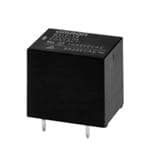
| 描述 | 通用继电器 Power PCB Relay SPDT 5VDC |
| 产品分类 | |
| 产品手册 | |
| 产品图片 |
|
| rohs | 符合RoHS |
| 产品系列 | 通用继电器,Omron Electronics G5LE-1-E-36-DC5 |
| mouser_ship_limit | 该产品可能需要其他文件才能进口到中国。 |
| 产品型号 | G5LE-1-E-36-DC5 |
| 产品 | Power Relays |
| 产品种类 | 通用继电器 |
| 功耗 | 360 mW |
| 商标 | Omron Electronics |
| 安装风格 | Through Hole |
| 工厂包装数量 | 100 |
| 端接类型 | Solder Pin |
| 类型 | Cube Style |
| 系列 | G5LE |
| 线圈电压 | 5 V |
| 线圈电流 | 72 mA |
| 线圈端接 | Solder Pin |
| 线圈类型 | Non-Latching |
| 触点形式 | SPDT (1 Form C) |
| 触点材料 | Silver Tin Oxide |
| 触点端接 | Pin |
| 零件号别名 | 660893 G5LE1E365DC G5LN8595H |


- 商务部:美国ITC正式对集成电路等产品启动337调查
- 曝三星4nm工艺存在良率问题 高通将骁龙8 Gen1或转产台积电
- 太阳诱电将投资9.5亿元在常州建新厂生产MLCC 预计2023年完工
- 英特尔发布欧洲新工厂建设计划 深化IDM 2.0 战略
- 台积电先进制程称霸业界 有大客户加持明年业绩稳了
- 达到5530亿美元!SIA预计今年全球半导体销售额将创下新高
- 英特尔拟将自动驾驶子公司Mobileye上市 估值或超500亿美元
- 三星加码芯片和SET,合并消费电子和移动部门,撤换高东真等 CEO
- 三星电子宣布重大人事变动 还合并消费电子和移动部门
- 海关总署:前11个月进口集成电路产品价值2.52万亿元 增长14.8%

PDF Datasheet 数据手册内容提取
G5LE PCB Power Relay Cubic, Single-pole 10A Power Relay •Ideal for a wide variety of applications such as home appliances, OA equipments, vending machines, etc. •Ambient Operating Temperature 85°C •UL class-B coil insulation for standard model. •UL, CSA, EN standards approved and conforms to Electrical Appliance and Material Safety Law (300 V max.). RoHS Compliant ■Model Number Legend ■Application Examples G5LE-@@@ •Home appliances — — — 1 2 3 •OA equipments 1. Number of Poles 3. Enclosure rating •Vending machines 1: 1-pole None:Flux protection 4: Fully sealed G 2. Contact Form 5 None:SPDT (1c) L A: SPST-NO (1a) E ■Ordering Information ■Characteristics Enclosure rating Flux protection Fully sealed Contact resistance *1 100 mΩ max. Minimun Terminal Rated coil Rated coil Operate time 10 ms max. Model Model packing unit Shape Classification Contact form voltage voltage Release time 5 ms max. 5 VDC 5 VDC Insulation resistance *2 100 MΩ min. SPDT (1c) G5LE-1 12 VDC G5LE-14 12 VDC Between 2,000 VAC, 50/60 Hz PCB 24 VDC 24 VDC 100 pcs/ coil and Standard for 1 min terminals 5 VDC 5 VDC tray contacts Dielectric SPST-NO (1a) G5LE-1A 12 VDC G5LE-1A4 12 VDC strength Between 24 VDC 24 VDC contacts of 750 VAC, 50/60 Hz the same for 1 min Note.When ordering, add the rated coil voltage to the model number. polarity Example: G5LE-1 DC5 Rated coil voltage Impulse between withstand coil and 4,500 V (1.2×50 μs) However, the notation of the coil voltage on the product case as well as on the packing will be marked voltage contacts as @@ VDC. 10 to 55 to 10 Hz, ■Ratings Destruction 0.75 mm single amplitude Vibration (1.5 mm double amplitude) ●Coil resistance 10 to 55 to 10 Hz, Malfunction 0.75 mm single amplitude Must operate Must release Max. (1.5 mm double amplitude) Rated Coil Power Rated voltage voltage voltage Shock Destruction 1,000 m/s2 current resistance consumption voltage (mA) (Ω) (V) (V) (V) (mW) resistance Malfunction 100 m/s2 % of rated voltage 10,000,000 operations min. Mechanical 5 VDC 79.4 63 (at 18,000 operations/hr) 170% Durability 12 VDC 33.3 360 75% max. 10% min. Approx. 400 100,000 operations min. at 23°C Electrical 24 VDC 16.7 1,440 (at 1,800 operations/hr) Note 1.The rated current and coil resistance are measured at a coil temperature of 23°C with a tolerance Failure rate (P level) 100 mA at 5 VDC of ±10%. (reference value) *3 2.The operating characteristics are measured at a coil temperature of 23°C. -25°C to 85°C Ambient operating 3.The “Max. voltage” is the maximum voltage that can be applied to the relay coil. (with no icing or temperature condensation) ●Contacts Ambient operating 35% to 85% humidity Item Load Resistive load Inductive lead (cosφ = 0.4) Weight Approx. 12 g Contact type Single Note.The data given above are initial values Contact material Ag-alloy (Cd free) *1. Measurement conditions: 5 VDC, 1 A, voltage Rated load 10 A at 120 VAC; 8 A at 30 VDC 5 A at 120 VAC; 4 A at 30 VDC drop method. Rated carry current 10 A *2. Measurement conditions: The insulation Max. switching voltage 250 VAC, 125 VDC (30 VDC when UL/CSA standard is applied) resistance was measured with a 500 VDC Max. switching current 10 A 5 A megohmmeter at the same locations as the dielectric strength was measured. *3. This value was measured at a switching frequency of 120 operations/min. 1
G5LE PCB Power Relay ■Engineering Data ●Maximum Switching Capacity ●Durability ●Ambient Temperature vs. Maximum Coil Voltage Switching current (A)531000753 AloACa(cCd roe sinsφids (cid:32)uti cv0te.i4ve) 4Durability (x10 operations)531000753000000 3re0s iVsDtivCe load1re2s0is VtivAeC l oad Maximum coil voltage (%)211086000 140 1 DC resistive 10 0.7 load 7 120 0.5 5 0.3 3 250 VAC resistive load 100 120 VAC inductive (cosφ = 0.4) 0 10 30 50 100 500 1,000 0 2 4 6 8 10 12 −025 20 30 40 50 60 70 80 90 100 Switching voltage (V) Switching current (V) Ambient temperature (°C) Note.The maximum coil voltage refers to the maximum value in a varying range of operating power voltage, not a continuous voltage. ●Shock Malfunction NO contact Y 1,000 NC contact G 1,000 1,000 5 X 500 Z’ L E Z Y Y’ Z 500 X’ X’ 1,000 1,000 Z’ X 1,000 Y’ Unit: m/s2 Shock direction Number of Relays:5 pcs Test Conditions: Shock was applied 3 times in each direction with and without excitation and the level at which the shock caused malfunction was measured. Rating: 100 m/s2 ■Dimensions G5LE-1 (SPDT contact) PCB Mounting Holes Terminal Arrangement/ G5LE-1A (SPST-NO contact) (Bottom View) Internal Connections (21.6)* (15.6)* Tolerance: ±0.1 mm unless (Bottom View) 22.5 max. 16.5 max. specified SPDT (1c) SPDT (1c) (18.56)* Five,1.3+ 00.2 dia. holes 19.0 max. (2.25) 2 3 0.5 12 1 3.5 5 4 0.2 1 1.2 0.4 *Average value 12.2 (2.55) 2 (5.75) (2.25) (Indicates average dimensions.) G5LE-14 (SPDT contact) G5LE-1A4 (SPST-NO contact) 22(2.51 .m6)a*x. 16(1.55 .m6)a*x. SPST-NO (1a) SPST-NO (1a) Four,1.3 + 00.2 dia. holes (2.25) 2 3 (18.5)* 19.0 max. 12 1 0.5 5 3.5 12.2 (2.55) 2 (5.75) (2.25) (Indicates average dimensions.) 0.2 1 1.2 0.4 *Average value Note. Orientation marks are indicated as follows: 2
G5LE PCB Power Relay ■Approved Standards UL Recognized: (File No. E41643) Coil Number of test Model Contact form Contact ratings ratings operations 10 A, 250 VAC (general use) at 40°C SPDT-NO (1a) 5 to 6,000 G5LE 8 A, 30 VDC SPDT (1c) 24 VDC (resistive load) at 40°C TV-3 (N.O only) 40°C 25,000 CSA Certified: (File No. LR31928) Coil Number of test Model Contact form Contact ratings ratings operations 10 A, 250 VAC (general use) at 40°C SPDT-NO (1a) 5 to 8 A, 30 VDC 6,000 G5LE SPDT (1c) 24 VDC (resistive load) at 40°C TV-3 (N.O only) 40°C 25,000 VDE EN/IEC Certified: (Certificate No. 6850) Coil Number of test Model Contact form Contact ratings ratings operations SPDT-NO (1a) 5, 12, 24 10 A, 250 VAC G5LE SPDT (1c) VDC (cosφ = 1) 85°C 50,000 TÜV EN/IEC Certified: (Certificate No. R50158258) Coil Number of test G Model Contact form Contact ratings ratings operations 5 2.5 A, 250 VAC L (cosφ = 0.4) 85°C 100,000 E SPDT-NO (1a) 5, 12, 24 10 A, 250 VAC G5LE 50,000 SPDT (1c) VDC (resistive load) at 85°C 8 A, 30 VAC 100,000 (resistive load) at 40°C ■Precautions •Please refer to “PCB Relays Common Precautions” for correct use. 3
G5LE PCB Power Relay G 5 L E (cid:129) Application examples provided in this document are for reference only. In actual applications, confirm equipment functions and safety before using the product. (cid:129) Consult your OMRON representative before using the product under conditions which are not described in the manual or applying the product to nuclear control systems, railroad systems, aviation systems, vehicles, combustion systems, medical equipment, amusement machines, safety equipment, and other systems or equipment that may have a serious influence on lives and property if used improperly. Make sure that the ratings and performance characteristics of the product provide a margin of safety for the system or equipment, and be sure to provide the system or equipment with double safety mechanisms. Note: Do not use this document to operate the Unit. OMRON Corporation Electronic and Mechanical Components Company Contact: www.omron.com/ecb Cat. No. K100-E1-07 1116(0207)(O) 4
Mouser Electronics Authorized Distributor Click to View Pricing, Inventory, Delivery & Lifecycle Information: O mron: G5LE-1-DC5 G5LE-14-DC24 G5LE-14-DC12 G5LE-1A4-DC6 G5LE-1A4-DC9 G5LE-1A4-DC5 G5LE-1-DC12 G5LE-1-DC24 G5LE-14-DC5 G5LE-14-DC6 G5LE-1A4-DC12 G5LE-1A4-DC24 G5LE-1A-DC24 G5LE-1-E-36-DC12 G5LE-1-E-DC12 G5LE-1A-E-DC5 G5LE-1A-E-DC24 G5LE-1-E-36-DC24 G5LE-1-E-36-DC5 G5LE-1A-E-DC12 G5LE-1-E-DC24 G5LE-1-E-DC5 G5LE-1-DC3 G5LE-1 DC18 G5LE-14 DC18 G5LE-14-36 DC12 G5LE-14-36 DC24 G5LE-14-36 DC9 G5LE-14-7 DC12 G5LE-14-AP3 DC18 G5LE-14-AP3 DC5 G5LE-14-AP3 DC6 G5LE-14-AP3-36 DC24 G5LE-14-ASI-36 DC18 G5LE-14-ASI-36 DC24 G5LE-14-CF DC12 G5LE-14-CF DC24 G5LE-14-CF DC9 G5LE-1A DC18 G5LE-1A4 DC18 G5LE-1A4-CF DC12 G5LE-1A4-CF DC24 G5LE-1A4-CF DC48 G5LE-1A4-CF DC9 G5LE-1A4-VD DC12 G5LE-1A4-VD DC9 G5LE-1A-CF DC12 G5LE-1A-CF DC18 G5LE-1A-CF DC5 G5LE-1A-CF DC9 G5LE-1-CF DC12 G5LE-14-AP3-DC12 G5LE-14-AP3-DC24 G5LE-1-36 DC5 G5LE-14-36 DC5 G5LE-14-36 DC60 G5LE-14-AP3 DC48 G5LE-14-AP3-36 DC12 G5LE-1A-E-36 DC24 G5LE-1A-E-36 DC5 G5LE-1A-S DC24 G5LE-1-ASI-60 DC24 G5LE-1-ASI-CF DC5 G5LE-1-ASI-VD DC24 G5LE-1A-VD DC12 G5LE-1-S DC24 G5LE-1-VD DC12 G5LE-1-VD DC24 G5LE-1 DC48 G5LE-1 DC6 G5LE-1 DC9 G5LE-14 DC3 G5LE-14 DC48 G5LE-14-ASI DC24 G5LE-14-ASI DC3 G5LE-14-ASI DC48 G5LE-14-ASI DC5 G5LE-14-ASI DC6 G5LE-14-ASI DC9 G5LE-1A DC12 G5LE-1A DC3 G5LE-1A DC5 G5LE-1A DC6 G5LE-1A4 DC3 G5LE-1A4 DC48 G5LE-1A4-ASI DC12 G5LE- 1A4-ASI DC24 G5LE-1A4-ASI DC3 G5LE-1A4-ASI DC6 G5LE-1A-ASI DC12 G5LE-1A-ASI DC24 G5LE-1A-ASI DC3 G5LE-1A-ASI DC5 G5LE-1-ASI DC24 G5LE-1-ASI DC3 G5LE-1-ASI DC48 G5LE-1-ASI DC5 G5LE-1-ASI DC6 G5LE-1-ASI DC9 G5LE-1-CF DC5