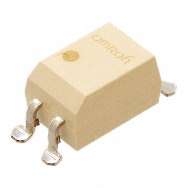
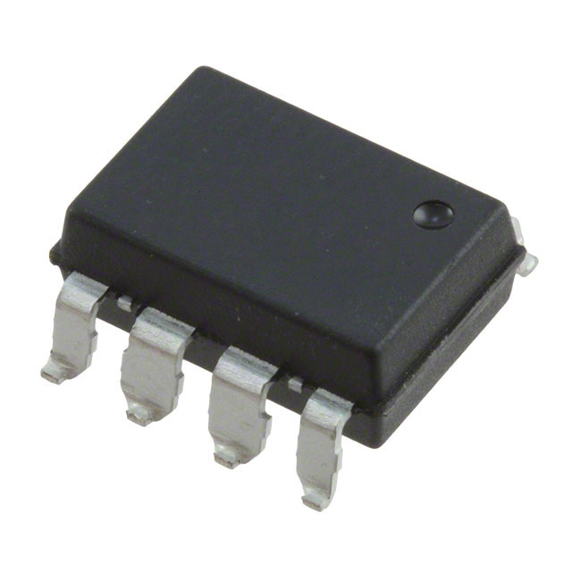
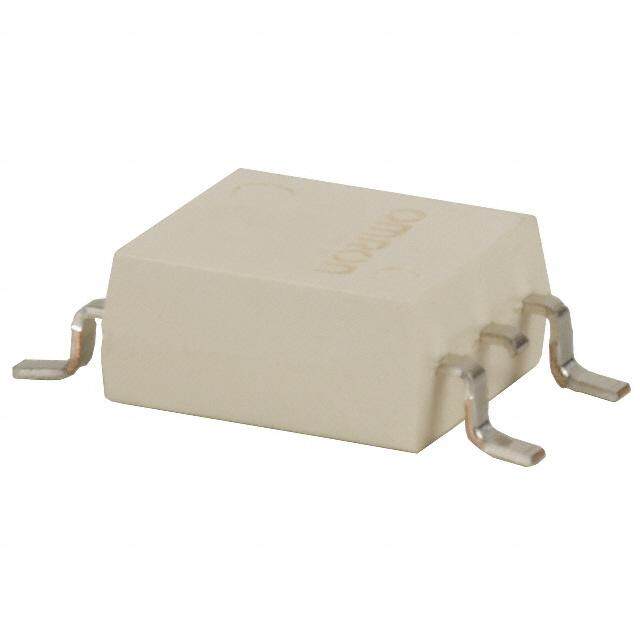
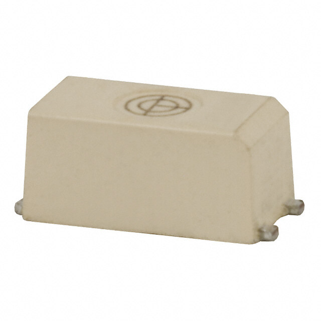
- 型号: G3VM-61HR
- 制造商: Omron Electronics LLC
- 库位|库存: xxxx|xxxx
- 要求:
| 数量阶梯 | 香港交货 | 国内含税 |
| +xxxx | $xxxx | ¥xxxx |
查看当月历史价格
查看今年历史价格
G3VM-61HR产品简介:
ICGOO电子元器件商城为您提供G3VM-61HR由Omron Electronics LLC设计生产,在icgoo商城现货销售,并且可以通过原厂、代理商等渠道进行代购。 G3VM-61HR价格参考¥55.77-¥66.92。Omron Electronics LLCG3VM-61HR封装/规格:固态继电器, 固体继电器 继电器 SPST-NO(1 Form A) 6-SOP(0.173",4.40mm)。您可以下载G3VM-61HR参考资料、Datasheet数据手册功能说明书,资料中有G3VM-61HR 详细功能的应用电路图电压和使用方法及教程。
| 参数 | 数值 |
| 产品目录 | |
| 描述 | RELAY SSR SPST 60V 2.3A 6SOP固态继电器-PCB安装 60V SPST-NO SOP6 SMT 2300mA .04ohm 70pF |
| 产品分类 | |
| 品牌 | Omron Electronics |
| 产品手册 | |
| 产品图片 |
|
| rohs | 符合RoHS无铅 / 符合限制有害物质指令(RoHS)规范要求 |
| 产品系列 | 固态继电器,固态继电器-PCB安装,Omron Electronics G3VM-61HRG3VM |
| mouser_ship_limit | 该产品可能需要其他文件才能进口到中国。 |
| 数据手册 | |
| 产品型号 | G3VM-61HR |
| 产品 | PCB Mount |
| 产品培训模块 | http://www.digikey.cn/PTM/IndividualPTM.page?site=cn&lang=zhs&ptm=25458http://www.digikey.cn/PTM/IndividualPTM.page?site=cn&lang=zhs&ptm=26145 |
| 产品种类 | 固态继电器-PCB安装 |
| 产品类型 | PCB Mount |
| 供应商器件封装 | 6-SOP |
| 其它名称 | G3VM61HR |
| 其它有关文件 | |
| 包装 | 管件 |
| 商标 | Omron Electronics |
| 安装类型 | 表面贴装 |
| 安装风格 | SMD/SMT |
| 导通电阻 | 70 毫欧 |
| 封装/外壳 | 6-SOP (0.173", 4.40mm) |
| 封装/箱体 | SOP-6 |
| 工厂包装数量 | 75 |
| 控制电压范围 | 1 V to 1.3 V |
| 标准包装 | 75 |
| 电压-负载 | 0 ~ 60 V |
| 电压-输入 | 1.33VDC |
| 电路 | SPST-NO(1 Form A) |
| 端子类型 | 鸥翼型 |
| 端接类型 | Gull Wing Lead |
| 系列 | G3VM |
| 继电器类型 | |
| 触点形式 | SPST (1 Form A) |
| 负载电压额定值 | 60 V |
| 负载电流 | 2.3A |
| 负载电流额定值 | 2.3 A |
| 输出类型 | AC,DC |
| 输出设备 | MOSFET |
| 零件号别名 | 692893 |


- 商务部:美国ITC正式对集成电路等产品启动337调查
- 曝三星4nm工艺存在良率问题 高通将骁龙8 Gen1或转产台积电
- 太阳诱电将投资9.5亿元在常州建新厂生产MLCC 预计2023年完工
- 英特尔发布欧洲新工厂建设计划 深化IDM 2.0 战略
- 台积电先进制程称霸业界 有大客户加持明年业绩稳了
- 达到5530亿美元!SIA预计今年全球半导体销售额将创下新高
- 英特尔拟将自动驾驶子公司Mobileye上市 估值或超500亿美元
- 三星加码芯片和SET,合并消费电子和移动部门,撤换高东真等 CEO
- 三星电子宣布重大人事变动 还合并消费电子和移动部门
- 海关总署:前11个月进口集成电路产品价值2.52万亿元 增长14.8%
PDF Datasheet 数据手册内容提取
MOS FET Relays G3VM-61HR Low 40-mΩ ON Resistance. Higher power, 2.3-A switching with a 60-V load voltage, SOP package. •Continuous load current of 2.3 A (connection C = 4.6 A). (cid:127)Dielectric strength of 1,500 Vrms between I/O. RoHS compliant ! Refer to “Common Precautions”. ■Application Examples Note: The actual product is marked differently from the image shown here. (cid:127)Broadband systems (cid:127)Measurement devices (cid:127)Data loggers (cid:127)Industrial equipment ■List of Models Contact form Terminals Load voltage (peak value) Model Number per stick Number per tape (See note.) SPST-NO Surface-mounting 60 V G3VM-61HR 75 --- terminals G3VM-61HR(TR) --- 2,500 Note: The AC peak and DC value is given for the load voltage. ■Dimensions Note: All units are in millimeters unless otherwise indicated. G3VM-61HR 4.4±0.25 6.3±0.25 2.1 max. 0.15 Note: The actual product is marked differently from the image shown here. 2.54±0.25 00..41±±00..11 7.00.±60±.40.3 Weight: 0.13 g ■Terminal Arrangement/Internal Connections (Top View) G3VM-61HR 6 5 4 1 2 3 ■Actual Mounting Pad Dimensions (Recommended Value, Top View) G3VM-61HR 6 to 6.3 1.2 0.8 2.54 2.54 54
G3VM-61HR G3VM-61HR ■Absolute Maximum Ratings (Ta = 25°C) Item Symbol Rating Unit Measurement Conditions Note: 1. The dielectric strength between the in- put and output was checked by apply- Input LED forward current IF 30 mA ing voltage between all pins as a LED forward current reduction rate ∆ IF/°C −0.3 mA/°C Ta ≥ 25°C ga rgoruopu po no nth eth eL EliDgh st-idreec aenivdin agl ls pidines. as LED reverse voltage VR 5 V Connection temperature Tj 125 °C Connection Diagram Output Load voltage (AC peak/DC) VOFF 60 V Continuous load Connection A IO 2.3 A Connection A: AC peak/DC 1 6 Load current Connection B 2.3 Connection B and C: DC Connection 2 5 or AC DC Connection C 4.6 A 3 4 ON current reduction Connection A ∆ IIO/°C −30.7 mA/°C Ta ≥ 50°C rate Connection B −30.7 Connection C −61.3 1 6 Load Pulse on current Iop 7 A t = 100 ms Connection 2 5 DC Connection temperature Tj 125 °C B 3 4 Dielectric strength between input and VI-O 1,500 Vrms AC for 1 min output (See note 1.) Operating temperature Ta −40 to +85 °C With no icing or condensation 1 6 Load Storage temperature Tstg −55 to +125 °C With no icing or condensation Connection 2 5 DC Soldering temperature (10 s) --- 260 °C 10 s C 3 4 ■Electrical Characteristics (Ta = 25°C) Item Symbol Mini- Typical Maxi- Unit Measurement mum mum conditions Input LED forward voltage VF 1.18 1.33 1.48 V IF = 10 mA Note: 2. TTuimrne-sON and Turn-OFF Reverse current IR --- --- 10 µA VR = 5 V Capacity between terminals CT --- 70 --- pF V = 0, f = 1 MHz IF 1 6 RL VDD Trigger LED forward current IFT --- 0.4 3 mA IO = 100 mA 2 4 VOUT Output Maximum resistance Connection A RON --- 0.04 0.07 Ω IF = 5 mA, IO = 2 A, t < 1S with output ON Connection B --- 0.02 0.04 Ω IF = 5 mA, IO = 2 A, t < 1S Connection C --- 0.01 --- Ω IF = 5 mA, IO = 4 A, t < 1S IF Current leakage when the relay is ILEAK --- --- 10 nA VOFF = 60 V open Capacity between I/O terminals CI-O --- 0.8 --- pF f = 1 MHz, Vs = 0 V VOUT 10% 90% Insulation resistance RI-O 1,000 --- --- MΩ VI-O = 500 VDC, tON tOFF RoH ≤ 60% Turn-ON time tON --- 1.0 5.0 ms IF = 5 mA, RL = 200 Ω, Turn-OFF time tOFF --- 0.15 1.0 ms VDD = 20 V (See note 2.) ■Recommended Operating Conditions Use the G3VM under the following conditions so that the Relay will operate properly. Item Symbol Minimum Typical Maximum Unit Load voltage (AC peak/DC) VDD --- --- 60 V Operating LED forward current IF 5 7.5 20 mA Continuous load current (AC peak/DC) IO --- --- 1.8 A Operating temperature Ta −20 --- 65 °C ■Engineering Data ■Safety Precautions Load Current vs. Ambient Temperature Refer to “Common Precautions” for all G3VM models. G3VM-61HR 6 A) nt ( urre 5 Connection C d c a o L 4 3 Connection A, Connection B 2 1 0 −20 0 20 40 60 80 100 Ambient temperature (°C) 55
Mouser Electronics Authorized Distributor Click to View Pricing, Inventory, Delivery & Lifecycle Information: O mron: G3VM-61HR(TR) G3VM-61HR
 Datasheet下载

