 Datasheet下载
- 型号: G3VM-351E
- 制造商: Omron Electronics LLC
- 库位|库存: xxxx|xxxx
- 要求:
| 数量阶梯 | 香港交货 | 国内含税 |
| +xxxx | $xxxx | ¥xxxx |
查看当月历史价格
查看今年历史价格
G3VM-351E产品简介:
ICGOO电子元器件商城为您提供G3VM-351E由Omron Electronics LLC设计生产,在icgoo商城现货销售,并且可以通过原厂、代理商等渠道进行代购。 G3VM-351E价格参考¥6.95-¥16.70。Omron Electronics LLCG3VM-351E封装/规格:固态继电器, 固体继电器 继电器 SPST-NO(1 Form A) 6-SMD(0.300",7.62mm)。您可以下载G3VM-351E参考资料、Datasheet数据手册功能说明书,资料中有G3VM-351E 详细功能的应用电路图电压和使用方法及教程。
| 参数 | 数值 |
| 产品目录 | |
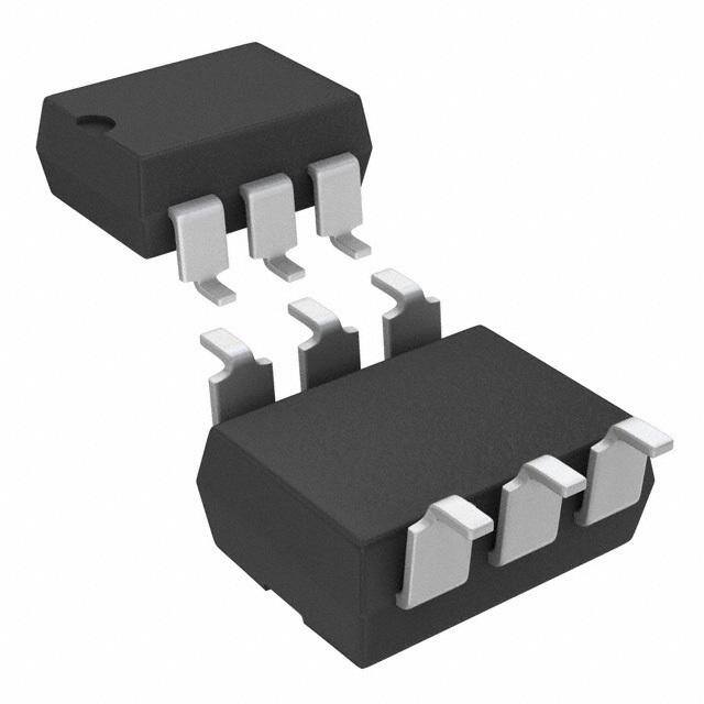
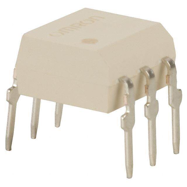
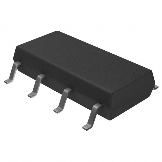
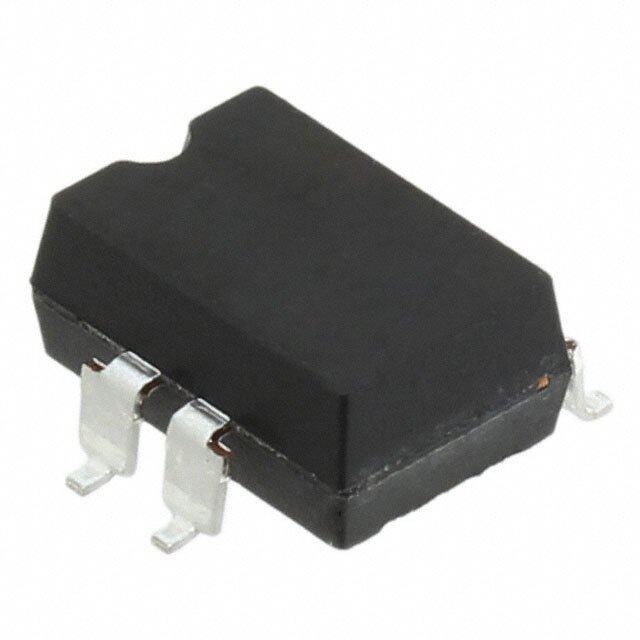
| 描述 | RELAY SSR SPST 350V 120MA 6SMT固态继电器-PCB安装 350V, SPST-NO, SMD6 SMT 120mA 35ohm 30pF |
| 产品分类 | |
| 品牌 | Omron Electronics |
| 产品手册 | |
| 产品图片 |
|
| rohs | 符合RoHS无铅 / 符合限制有害物质指令(RoHS)规范要求 |
| 产品系列 | 固态继电器,固态继电器-PCB安装,Omron Electronics G3VM-351EG3VM |
| mouser_ship_limit | 该产品可能需要其他文件才能进口到中国。 |
| 数据手册 | |
| 产品型号 | G3VM-351E |
| 产品 | Power Relays |
| 产品培训模块 | http://www.digikey.cn/PTM/IndividualPTM.page?site=cn&lang=zhs&ptm=25458http://www.digikey.cn/PTM/IndividualPTM.page?site=cn&lang=zhs&ptm=26145 |
| 产品目录绘图 |
|
| 产品目录页面 | |
| 产品种类 | 固态继电器-PCB安装 |
| 产品类型 | PCB Mount |
| 供应商器件封装 | 6-SMD |
| 其它名称 | G3VM351E |
| 其它有关文件 | |
| 包装 | 管件 |
| 商标 | Omron Electronics |
| 安装类型 | 表面贴装 |
| 安装风格 | SMD/SMT |
| 导通电阻 | 50 欧姆 |
| 封装/外壳 | 6-SMD(0.300",7.62mm) |
| 封装/箱体 | SMD DIP-6 |
| 工厂包装数量 | 50 |
| 控制电压范围 | 1 V to 1.3 V |
| 标准包装 | 50 |
| 电压-负载 | 0 ~ 350 V |
| 电压-输入 | 1.15VDC |
| 电路 | SPST-NO(1 A 形) |
| 端子类型 | 鸥翼型 |
| 端接类型 | Gull Wing Lead |
| 系列 | G3VM |
| 继电器类型 | |
| 触点形式 | SPST (1 Form A) |
| 负载电压额定值 | 350 V |
| 负载电流 | 120mA |
| 负载电流额定值 | 120 mA |
| 输入电流 | 50 mA |
| 输入转输出绝缘方法 | Optocoupler |
| 输出类型 | AC,DC |
| 输出设备 | MOSFET |
| 零件号别名 | G3VM351ENC |


- 商务部:美国ITC正式对集成电路等产品启动337调查
- 曝三星4nm工艺存在良率问题 高通将骁龙8 Gen1或转产台积电
- 太阳诱电将投资9.5亿元在常州建新厂生产MLCC 预计2023年完工
- 英特尔发布欧洲新工厂建设计划 深化IDM 2.0 战略
- 台积电先进制程称霸业界 有大客户加持明年业绩稳了
- 达到5530亿美元!SIA预计今年全球半导体销售额将创下新高
- 英特尔拟将自动驾驶子公司Mobileye上市 估值或超500亿美元
- 三星加码芯片和SET,合并消费电子和移动部门,撤换高东真等 CEO
- 三星电子宣布重大人事变动 还合并消费电子和移动部门
- 海关总署:前11个月进口集成电路产品价值2.52万亿元 增长14.8%


PDF Datasheet 数据手册内容提取
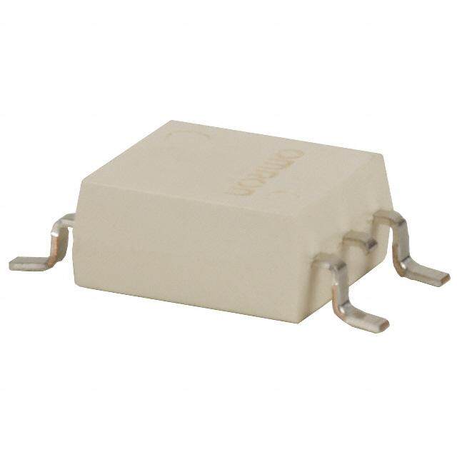
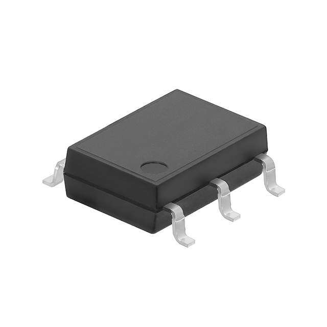
G3VM-351B/E MOS FET Relays General-purpose Series with 350-V Load Voltage. •Upgraded G3VM-3 Series. •Continuous load current of 120 mA. •Dielectric strength of 2,500 Vrms between I/O. •Operating time of 0.3 ms (typical). RoHS compliant Note:The actual product is marked differently from the image shown here. ■Application Examples ■Terminal Arrangement/Internal Connections •Test & Measurement equipment 6 5 4 •Security equipment OMRON logo Model name •Amusement equipment Pin 1 mark 932 LOT.NO. 1 2 3 Note:The actual product is marked differently from the image shown here. ■List of Models Load voltage Minimum package quantity Package type Contact form Terminals Model (peak value) * Number per tube Number per tape and reel PCB Terminals G3VM-351B 1a 50 - DIP6 350 V G3VM-351E (SPST-NO) Surface-mounting Terminals G3VM-351E (TR) - 1,500 *The AC peak and DC value are given for the load voltage. ■Absolute Maximum Ratings (Ta = 25°C) Item Symbol Rating Unit Measurement conditions Note:1.The dielectric strength between the input and output was LED forward current IF 50 mA checked by applying voltage between all pins as a group on put RLEepDe ftoitrivwea prde acku LrrEeDn tf orerwduacrdti ocunr rraetnet ∆IIFF/P°C −01. 5 mAA/° C 1T0a0 ≥ µ 2s5 p°Cul ses, 100 pps Ctheo LnEnDe scidteio annd D alila pginrsa ams a group on the light-receiving side. n I LED reverse voltage VR 5 V Connection temperature TJ 125 °C Connection 1 6 Load Load voltage (AC peak/DC) VOFF 350 V A 2 5 or AC DC Connection A 120 3 4 Continuous Connection A: AC peak/DC ut load current CCoonnnneeccttiioonn BC IO 122400 mA Connection B and C: DC p 1 6 Load ut ON current Connection A −1.2 Connection O reduction Connection B ∆IO/°C −1.2 mA/°C Ta ≥ 25°C B 2 5 DC rate Connection C −2.4 3 4 Connection temperature TJ 125 °C Dielectric strength between I/O (See note 1.) VI-O 2500 Vrms AC for 1 min 1 6 Load Connection Ambient operating temperature Ta −40 to +85 °C With no icing or condensation C 2 5 DC Ambient storage temperature Tstg −55 to +125 °C With no icing or condensation 3 4 Soldering temperature - 260 °C 10 s ■Electrical Characteristics (Ta = 25°C) Item Symbol Minimum Typical Maximum Unit Measurement conditions LED forward voltage VF 1.0 1.15 1.3 V IF = 10 mA ut Reverse current IR - - 10 µA VR = 5 V p n Capacity between terminals CT - 30 - pF V = 0, f = 1 MHz I Trigger LED forward current IFT - 1 3 mA IO = 120 mA Note:2.Turn-ON and Turn-OFF Times put Mroeuastxipsiumtat unOmcNe with CCoonnnneeccttiioonn AB RON --- 232558 354500 ΩΩΩ IIIFFF === 555 mmmAAA, ,,I OIIOO = == 1 211022 00m mmA,AA t<1 s IF 12 64 RL VVDODUT ut Connection C - 14 20 Ω IF = 5 mA, IO = 240 mA O Current leakage when the relay is open ILEAK - - 1.0 µA VOFF = 350 V Capacity between terminals COFF - 30 - pF V = 0, f = 1 MHz IF Capacity between I/O terminals CI-O - 0.8 - pF f = 1 MHz, VS = 0 V Insulation resistance between I/O terminals RI-O 1000 - - MΩ VI-O = 500 VDC, ROH ≤ 60% Turn-ON time tON - 0.3 1.0 ms IF = 5 mA, RL = 200 Ω, VOUT 10% 90% Turn-OFF time tOFF - 0.1 1.0 ms VDD = 20 V(See note 2.) tON tOFF 1
G3VM-351B/E MOS FET Relays ■Recommended Operating Conditions Use the G3VM under the following conditions so that the Relay will operate properly. Item Symbol Minimum Typical Maximum Unit Load voltage (AC peak/DC) VDD - - 280 V Operating LED forward current IF 5 10 25 mA Continuous load current (AC peak/DC) IO - - 100 mA Ambient operating temperature Ta −20 - 65 °C ■Engineering Data LED forward current vs. Ambient Continuous load current vs. Ambient LED forward current vs. LED forward temperature temperature voltage IF - Ta IO - Ta IF - VF mA)100 mA)280 mA) 100 Ta = 25°C LED forward current I (F 648000 ntinuous load current I (O 221140620000 CCoonnnneecctitoionn A C and B LED forward current I (F 310031 Co 80 20 40 0.3 0 0 0.1 -20 0 20 40 60 80 100 120 -20 0 20 40 60 80 100 120 0.6 0.8 1 1.2 1.4 1.6 1.8 Ambient temperature Ta (°C) Ambient temperature Ta (°C) LED forward voltage VF (V) Continuous load current vs. On-state On-state resistance vs. Ambient Trigger LED forward current vs. voltage temperature Ambient temperature IO - VON RON - Ta IFT - Ta ntinuous load current I (mA)O 1200000 TICFao = n= n5 2em5cA°tiCon A ΩOn-state resistance R ()ON 32450000 ItCIOF <o = =n1 n5s1em2c0AtmionA A LED forward current I (mA)FT 3245 ItO < =1 s120mA Co-100 ger 10 Trig 1 -200 0 0 -4 -3 -2 -1 0 1 2 3 4 -20 0 20 40 60 80 100 -20 0 20 40 60 80 100 On-state voltage VON (V) Ambient temperature Ta (°C) Ambient temperature Ta (°C) Turn ON, Turn OFF time vs. LED Turn ON, Turn OFF time vs. Ambient Current leakage vs. Ambient forward current temperature temperature tON, tOFF - IF tON, tOFF - Ta ILEAK - Ta N, Turn OFF time t, t (µs)ONOFF 13001300000000 tOFFTVRaDL D== =22 0520º0CΩV N, Turn OFF time t, t (µs)ONOFF13003100000000 ttOONFF Current leakage I (nA)LEAK 133001 VOFF = 350V O O Turn 30 tON Turn 30 VRDL D= =2 0200ΩV 0.3 10 10 IF = 5mA 0.1 1 3 10 30 100 300 -20 0 20 40 60 80 100 -20 0 20 40 60 80 100 LED forward current IF (mA) Ambient temperature Ta (°C) Ambient temperature Ta (°C) ■Safety Precautions •Refer to "Common Precautions" for all G3VM models. 2
Appearance/Dimensions DIP6 type ■Appearance DDIIPP ((DDuuaall IInnlliinnee PPaacckkaaggee)) DIP6 OMRON logo Model name Pin 1 mark 932 LOT.NO. Note: The actual product is marked differently from the image shown here. ■Dimensions (Unit:mm) PCB Terminals Surface-mounting Terminals PCB Dimensions (BOTTOM VIEW) Weight: 0.4 g Weight: 0.4 g Six, 0.8-dia. holes 2.54 (0.61) 2.54 7.12±0.25 7.12±0.25 (0.61) 6.4±0.25 (1.52) (1.52) 6.4±0.25 7.62±0.25 Actual Mounting Pad Dimensions 0.8±0.25 7.62±0.25 (Recommended Value, TOP VIEW) 3.65+−00..1255 0.25+−00..105 3.65+−00..1255 4.0+−00..225 2.54 2.54 1.0 min. 2.5 min. 0.5±10..12±0.15 7.85 to 8.80 1.2±0.15 1.0 min. 8.3 to 8.8 2.54±0.25 2.54±0.25 10.0 max. Note:The actual product is marked differently from the 1.3 image shown here. 1.5 • Application examples provided in this document are for reference only. In actual applications, confirm equipment functions and safety before using the product. • Consult your OMRON representative before using the product under conditions which are not described in the manual or applying the product to nuclear control systems, railroad systems, aviation systems, vehicles, combustion systems, medical equipment, amusement machines, safety equipment, and other systems or equipment that may have a serious influence on lives and property if used improperly. Make sure that the ratings and performance characteristics of the product provide a margin of safety for the system or equipment, and be sure to provide the system or equipment with double safety mechanisms. Note: Do not use this document to operate the Unit. OMRON Corporation ELECTRONIC AND MECHANICAL COMPONENTS COMPANY Contact: www.omron.com/ecb Cat. No. K147-E1-01 0412(0412)(O)