ICGOO在线商城 > FT-X-GPS
- 型号: FT-X-GPS
- 制造商: FTDI
- 库位|库存: xxxx|xxxx
- 要求:
| 数量阶梯 | 香港交货 | 国内含税 |
| +xxxx | $xxxx | ¥xxxx |
查看当月历史价格
查看今年历史价格
FT-X-GPS产品简介:
ICGOO电子元器件商城为您提供FT-X-GPS由FTDI设计生产,在icgoo商城现货销售,并且可以通过原厂、代理商等渠道进行代购。 提供FT-X-GPS价格参考以及FTDIFT-X-GPS封装/规格参数等产品信息。 你可以下载FT-X-GPS参考资料、Datasheet数据手册功能说明书, 资料中有FT-X-GPS详细功能的应用电路图电压和使用方法及教程。
| 参数 | 数值 |
| 产品目录 | |
| 描述 | MOD USB GPS DONGLEGPS模块 Packaged GPS USB Type A USB Dongle |
| 产品分类 | RF 接收器、发射器及收发器的成品装置射频/无线模块 |
| 品牌 | FTDI |
| 产品手册 | |
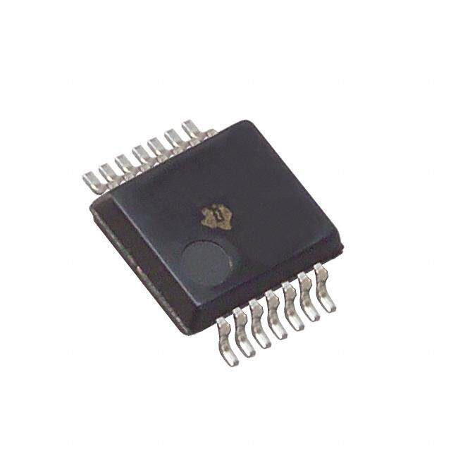
| 产品图片 |
|
| rohs | 符合RoHS无铅 / 符合限制有害物质指令(RoHS)规范要求 |
| 产品系列 | GPS模块,FTDI FT-X-GPS- |
| 数据手册 | |
| 产品型号 | FT-X-GPS |
| 产品种类 | GPS模块 |
| 其它名称 | 768-1206 |
| 其它有关文件 | |
| 功率-输出 | - |
| 功能 | 接收器 |
| 商标 | FTDI |
| 商标名 | X-Chip |
| 安装风格 | SMD/SMT |
| 封装 | Bulk |
| 尺寸 | 60.3 mm x 20.3 mm x 12.3 mm |
| 工作电源电压 | 1.8 V |
| 工作电源电流 | 65 mA |
| 工厂包装数量 | 10 |
| 应用 | GPS |
| 接口 | USB |
| 接口类型 | GUI |
| 数据速率(最大值) | - |
| 最大工作温度 | + 85 C |
| 最小工作温度 | - 40 C |
| 标准包装 | 1 |
| 水平位置精确度 | 2.5 m |
| 灵敏度 | -163dBm |
| 特性 | - |
| 电压-电源 | 5V,USB |
| 系列 | FT230X |
| 获取敏感性 | - 163 dBm |
| 调制或协议 | GPS |
| 通道数量 | 48 Channel |
| 频带 | 1.575 GHz |
| 频率 | - |
| 首次固定时间—冷启动 | 35 s |




- 商务部:美国ITC正式对集成电路等产品启动337调查
- 曝三星4nm工艺存在良率问题 高通将骁龙8 Gen1或转产台积电
- 太阳诱电将投资9.5亿元在常州建新厂生产MLCC 预计2023年完工
- 英特尔发布欧洲新工厂建设计划 深化IDM 2.0 战略
- 台积电先进制程称霸业界 有大客户加持明年业绩稳了
- 达到5530亿美元!SIA预计今年全球半导体销售额将创下新高
- 英特尔拟将自动驾驶子公司Mobileye上市 估值或超500亿美元
- 三星加码芯片和SET,合并消费电子和移动部门,撤换高东真等 CEO
- 三星电子宣布重大人事变动 还合并消费电子和移动部门
- 海关总署:前11个月进口集成电路产品价值2.52万亿元 增长14.8%


PDF Datasheet 数据手册内容提取
Application Note AN_216 Using the FT230X to design a GPS Dongle Version 1.1 Issue Date: 2013-09-09 This application note illustrates how to develop a GPS to USB design using the FTDI FT230X chip. Use of FTDI devices in life support and/or safety applications is entirely at the user’s risk, and the user agrees to defend, indemnify and hold FTDI harmless from any and all damages, claims, suits or expense resulting from such use. Future Technology Devices International Limited (FTDI) Unit 1, 2 Seaward Place, Glasgow G41 1HH, United Kingdom Tel.: +44 (0) 141 429 2777 Fax: + 44 (0) 141 429 2758 Web Site: http://ftdichip.com Copyright © 2012 Future Technology Devices International Limited
Application Note AN_216 Using the FT230X to design a GPS Dongle Version 1.1 Document Reference No.: FT_000698 Clearance No.: FTDI# 301 Table of Contents 1 Introduction .................................................................................................................................... 2 1.1 Overview ................................................................................................................................. 2 1.2 Background ............................................................................................................................. 2 2 Example Circuit ............................................................................................................................... 3 3 PCB Data .......................................................................................................................................... 6 4 Using FT230XQ GPS Dongle as a location sensor under Windows 7 .............................................. 7 5 Contact Information ........................................................................................................................ 9 Appendix A – References ...................................................................................................................... 10 Document References ....................................................................................................................... 10 Acronyms and Abbreviations ............................................................................................................ 10 Appendix B – List of Figures .................................................................................................................. 11 List of Figures .................................................................................................................................... 11 Appendix C – Revision History .............................................................................................................. 12 1 Copyright © 2013 Future Technology Devices International Limited
Application Note AN_216 Using the FT230X to design a GPS Dongle Version 1.1 Document Reference No.: FT_000698 Clearance No.: FTDI# 301 1 Introduction The FT230X is a USB to serial UART interface with optimised pin count for smaller PCB designs, offering single-chip USB to asynchronous serial data transfer interface. The entire USB protocol is handled on the chip. No USB specific firmware programming is required. Small PCB footprint makes it ideal for space constrained applications such as the design of a GPS dongle – as described in this application note. 1.1 Overview This application note gives detail of how to implement a GPS dongle design, which can be used to enable location services under Windows Operating System, using the FT230X USB to basic UART Bridge IC. The application can be used as a reference design for the FT230X and details of the schematic and layout are given for reference. 1.2 Background Computers today are more mobile than ever. From small laptops to Tablet PCs, many computers can go wherever the user wants to go. Programs that take advantage of the computer's mobility can add significant value to people's lives. For example, a program that can find nearby restaurants and provide driving directions would seem to be a natural fit for a portable computer. Starting with Windows 7, the Windows Sensor and Location platform enables the computer and applications to adapt to their current environment. With location sensors – such as GPS devices, applications and gadgets can know exactly where they are, enabling them to provide relevant content and functionality. 2 Copyright © 2013 Future Technology Devices International Limited
Application Note AN_216 Using the FT230X to design a GPS Dongle Version 1.1 Document Reference No.: FT_000698 Clearance No.: FTDI# 301 2 Example Circuit The schematic diagram below gives details of how the FT230XQ chip can be connected to a GPS receiver to create a USB based GPS sensor. In this case a GPS module – GP-2106 has been used. M11VCC2GND31PPS4ON/OFF5RX6TX GP-2106 C cable 6-pin 0.5mm pitch VBUS R9560R LED1Blue Q2IRLML2502R8100k GND CN2 123456 503480-0600 GNDCB1 FPC/FF R71PPS2k R1010kN.F. 1PPS 5Q VC1G123 GND R11R1210k10k 3V3OUT 8U31AC2CBV3CLR 7DCX/RXN6CXG 74L4 GND 3V3OUTC14 0.1uF C104.7uF ND R61M C120.1uF G C90.1uF D N U3 G G2 U4AIC1747-183VinVoutGNDC7C810.1uF0.1uF GNDGND 3V3OUT 8U21AC2CBV3CLR5Q 7DCX/RXN6CXG 74LVC1G1234 GND 3V3OUTC13 0.1uFGND ML6402 R51M C111uF Q1IRL R4100k R32k 152164 1211514 TXDRXDRTS#CTS# CBUS0CBUS1CBUS2CBUS3 FT230XQ 011 COCICVCV DDDNNNGGG 33711 GND U1 3V3OUT USBDMUSBDP RESET# V3OUT 8 76 9 C60.1uF GND 3 RR 2727 R1R2 VBUS C5C40.1uF4.7uF GNDGND FB1600R/0.5A C3C1C210nF 2x47pFGND 1234 CN1 VBUSD-D+GND B Plug US Figure 2.1 FT230XQ GPS Dongle circuit diagram 3 Copyright © 2013 Future Technology Devices International Limited
Application Note AN_216 Using the FT230X to design a GPS Dongle Version 1.1 Document Reference No.: FT_000698 Clearance No.: FTDI# 301 The FT230XQ (U1) provides the UART to USB conversion while GPS Module – GP-2106 (M1) provides location data in NMEA0183 v.3.01 format. For more information about GP-2106 GPS receiver please visit the product web site: http://www.adh-tech.com.tw/?gp-2106(sirf-star-iv),71 More information on the FT230XS may be obtained from the FTDI web page: http://www.ftdichip.com/Products/ICs/FT230X.html The implementation is straight-forward with TXD output from the FT230XQ connected to RXD input of the GP-2106 GPS receiver and RXD input of the FT230XQ connected to TXD output from the GP-2106. These connections form a data link between the GPS receiver and USB port. RTS# and CTS# pins of the FT230XQ are connected together to disable hardware flow control. To properly start-up the GPS receiver, power must be applied and ‘On’ pulse must be generated at pin-4 of the receiver. To satisfy this condition two monostable multivibrators (74LVC1G123) have been employed. First multivibrator U2 generates a delay during which the FT230XQ is enumerated by the USB host controller and power is applied to the GPS receiver. The second multivibrator generates an ‘On’ pulse (high level) which starts-up the chipset inside the GPS receiver module. Figure below illustrates the behaviour of the start-up circuit. Figure 2.2 Start-up circuit scope waveforms CH.1 (Yellow trace) was taken from the U1-pin-12 (CBUS0). CBUS0 is configured as an output of PWREN# signal. CH.2 (Blue trace) probe was connected to the ‘Q’ output of U2. CH.3 (Purple trace) probe was connected to the ‘Q’ output of U3. 4 Copyright © 2013 Future Technology Devices International Limited
Application Note AN_216 Using the FT230X to design a GPS Dongle Version 1.1 Document Reference No.: FT_000698 Clearance No.: FTDI# 301 The PWREN# pin toggles during the USB enumeration process and then it stays low as long as U1 is enumerated and the host computer is not in ‘sleep’ mode (i.e. it is not hibernated). A logic low level at this pin also enables the Q1 MOSFET transistor to conduct, feeding ‘VBUS’ (+5V) to the input of U4 voltage regulator. U4 reduces this voltage to 1.8V required by the GPS receiver. As soon as PWREN# pin goes low for the first time, U2 triggers, driving its output high. Approximately 1.6 seconds later U2 output will go low triggering U3 which will generate ‘On’ pulse at the ‘ON/OFF’ input of the GPS receiver. GPS dongle PCB has been equipped with the blue status LED (LED1). This LED will blink once a second when GPS fix is available (valid position has been acquired). LED1 is controlled by ‘1PPS’ output from GPS receiver through Q2 MOSFET transistor. 5 Copyright © 2013 Future Technology Devices International Limited
Application Note AN_216 Using the FT230X to design a GPS Dongle Version 1.1 Document Reference No.: FT_000698 Clearance No.: FTDI# 301 3 PCB Data FT230XQ GPS Dongle PCB files are available in Gerber format and Altium Designer project files and can be downloaded here: http://www.ftdichip.com/support/documents/schematics/HW_248_rev1_1.zip 6 Copyright © 2013 Future Technology Devices International Limited
Application Note AN_216 Using the FT230X to design a GPS Dongle Version 1.1 Document Reference No.: FT_000698 Clearance No.: FTDI# 301 4 Using FT230XQ GPS Dongle as a location sensor under Windows 7 To use FT230XQ GPS Dongle as a location sensor, a special driver must be installed. There are many location sensor drivers freely available on the web. One of them can be downloaded from following location: http://www.turboirc.com/gps7/ 7 Copyright © 2013 Future Technology Devices International Limited
Application Note AN_216 Using the FT230X to design a GPS Dongle Version 1.1 Document Reference No.: FT_000698 Clearance No.: FTDI# 301 5 Ordering Information Due to the large volume of interest expressed in this solution by FTDI customers, FTDI are delighted to offer a finished product, ready to use in a tough, contoured, hardened plastic enclosure. The module has a type A USB connector with dust cap for connecting to the USB host and will be powered from the USB host. Figure 5.1 FT-X-GPS Dongle Module Code Utilised IC Code Description FT-X-GPS FT230XQ USB GPS Dongle Table 5-1 – Ordering Information Drivers for the FT230X are available at: http://www.ftdichip.com/Drivers/VCP.htm 8 Copyright © 2013 Future Technology Devices International Limited
Application Note AN_216 Using the FT230X to design a GPS Dongle Version 1.1 Document Reference No.: FT_000698 Clearance No.: FTDI# 301 6 Contact Information Head Office – Glasgow, UK Branch Office – Tigard, Oregon, USA Future Technology Devices International Limited Future Technology Devices International Limited Unit 1, 2 Seaward Place, Centurion Business Park (USA) Glasgow G41 1HH 7130 SW Fir Loop United Kingdom Tigard, OR 97223 Tel: +44 (0) 141 429 2777 USA Fax: +44 (0) 141 429 2758 Tel: +1 (503) 547 0988 Fax: +1 (503) 547 0987 E-mail (Sales) sales1@ftdichip.com E-mail (Support) support1@ftdichip.com E-Mail (Sales) us.sales@ftdichip.com E-mail (General Enquiries) admin1@ftdichip.com E-Mail (Support) us.support@ftdichip.com E-Mail (General Enquiries) us.admin@ftdichip.com Branch Office – Taipei, Taiwan Branch Office – Shanghai, China Future Technology Devices International Limited Future Technology Devices International Limited (Taiwan) (China) 2F, No. 516, Sec. 1, NeiHu Road Room 1103, No. 666 West Huaihai Road, Taipei 114 Shanghai, 200052 Taiwan , R.O.C. Tel: +886 (0) 2 8791 3570 China Fax: +886 (0) 2 8791 3576 Tel: +86 21 62351596 Fax: +86 21 62351595 E-mail (Sales) asia.sales1@ftdichip.com asia.support1@ftdichip.co E-mail (Sales) cn.sales@ftdichip.com E-mail (Support) m E-mail (Support) cn.support@ftdichip.com E-mail (General Enquiries) asia.admin1@ftdichip.com E-mail (General Enquiries) cn.admin@ftdichip.com Web Site http://ftdichip.com System and equipment manufacturers and designers are responsible to ensure that their systems, and any Future Technology Devices International Ltd (FTDI) devices incorporated in their systems, meet all applicable safety, regulatory and system-level performance requirements. All application-related information in this document (including application descriptions, suggested FTDI devices and other materials) is provided for reference only. While FTDI has taken care to assure it is accurate, this information is subject to customer confirmation, and FTDI disclaims all liability for system designs and for any applications assistance provided by FTDI. Use of FTDI devices in life support and/or safety applications is entirely at the user’s risk, and the user agrees to defend, indemnify and hold harmless FTDI from any and all damages, claims, suits or expense resulting from such use. This document is subject to change without notice. No freedom to use patents or other intellectual property rights is implied by the publication of this document. Neither the whole nor any part of the information contained in, or the product described in this document, may be adapted or reproduced in any material or electronic form without the prior written consent of the copyright holder. Future Technology Devices International Ltd, Unit 1, 2 Seaward Place, Centurion Business Park, Glasgow G41 1HH, United Kingdom. Scotland Registered Company Number: SC136640 9 Copyright © 2013 Future Technology Devices International Limited
Application Note AN_216 Using the FT230X to design a GPS Dongle Version 1.1 Document Reference No.: FT_000698 Clearance No.: FTDI# 301 Appendix A – References Document References FT230XQ webpage: http://www.ftdichip.com/Support/Documents/DataSheets/ICs/DS_FT230X.pdf GP-2106 webpage: http://www.adh-tech.com.tw/?gp-2106(sirf-star-iv),71 Information on GPS system: http://en.wikipedia.org/wiki/Global_Positioning_System Information on Windows Location API: Acronyms and Abbreviations Terms Description GPS Global Positioning System LED Light Emitting Diode MOSFET Metal–Oxide–Semiconductor Field-Effect Transistor RXD Receive Data (The receive data line of RS232) TXD Transmit Data (The transmit data line of RS232) UART Universal Asynchronous Receiver/Transmitter USB Universal Serial Bus USB-IF USB Implementers Forum 10 Copyright © 2013 Future Technology Devices International Limited
Application Note AN_216 Using the FT230X to design a GPS Dongle Version 1.1 Document Reference No.: FT_000698 Clearance No.: FTDI# 301 Appendix B – List of Figures List of Figures Figure 2.1 FT230XQ GPS Dongle circuit diagram ..................................................................... 3 Figure 2.2 Start-up circuit scope waveforms ........................................................................... 4 Figure 5.1 FT-X-GPS Dongle ................................................................................................. 8 List of tables Table 5-1 – Ordering Information .......................................................................................... 8 11 Copyright © 2013 Future Technology Devices International Limited
Application Note AN_216 Using the FT230X to design a GPS Dongle Version 1.1 Document Reference No.: FT_000698 Clearance No.: FTDI# 301 Appendix C – Revision History Document Title: AN_216 Using the FT230X to design a GPS Dongle Document Reference No.: FT_000698 Clearance No.: FTDI# 301 Product Page: http://www.ftdichip.com/Support.htm/FTReferenceDesigns.htm Document Feedback: Send Feedback Revision Changes Date 1.0 Initial Release 2012-07-09 Included details of dongle for retail. 1.1 Updated US contact details 2013-08-08 Added image in section 5 12 Copyright © 2013 Future Technology Devices International Limited
Mouser Electronics Authorized Distributor Click to View Pricing, Inventory, Delivery & Lifecycle Information: F TDI: FT-X-GPS
/MFG_FT-X-GPS.JPG)
 Datasheet下载
