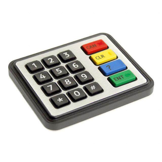
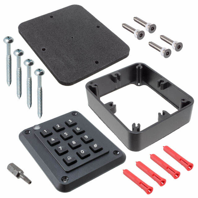
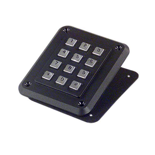
- 型号: FMBP16BF
- 制造商: NKK Switches
- 库位|库存: xxxx|xxxx
- 要求:
| 数量阶梯 | 香港交货 | 国内含税 |
| +xxxx | $xxxx | ¥xxxx |
查看当月历史价格
查看今年历史价格
FMBP16BF产品简介:
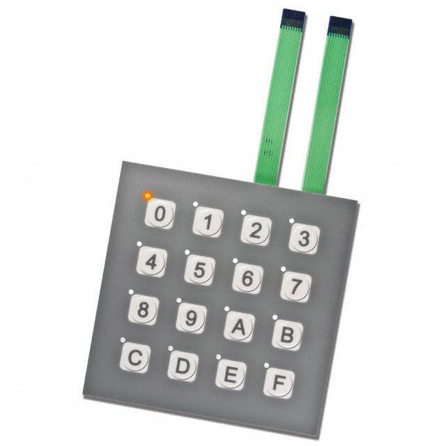
ICGOO电子元器件商城为您提供FMBP16BF由NKK Switches设计生产,在icgoo商城现货销售,并且可以通过原厂、代理商等渠道进行代购。 FMBP16BF价格参考。NKK SwitchesFMBP16BF封装/规格:小键盘开关, Keypad Switch 16 Polyester Overlay Keys Membrane (Snap Dome) Contacts Matrix Output Illuminated - Amber 0.02A @ 24VDC。您可以下载FMBP16BF参考资料、Datasheet数据手册功能说明书,资料中有FMBP16BF 详细功能的应用电路图电压和使用方法及教程。
| 参数 | 数值 |
| 产品目录 | |
| 描述 | KEYPAD 16 KEY ILLUM MEMBRANE GRY输入设备 16KEY NONILLUMINATED MEMBRANE SWTCH GRAY |
| 产品分类 | |
| 品牌 | NKK Switches |
| 产品手册 | |
| 产品图片 |
|
| rohs | 符合RoHS无铅 / 符合限制有害物质指令(RoHS)规范要求 |
| 产品系列 | 输入设备,NKK Switches FMBP16BFFM |
| mouser_ship_limit | 该产品可能需要其他文件才能进口到中国。 |
| 数据手册 | |
| 产品型号 | FMBP16BF |
| 产品目录页面 | |
| 产品种类 | 输入设备 |
| 其它名称 | 360-2299 |
| 可互换图例 | 无 |
| 商标 | NKK Switches |
| 图例 | 0 ~ 9,A ~ F |
| 密封等级 | 无 |
| 工厂包装数量 | 1 |
| 开关类型 | 膜片(圆顶按钮) |
| 按键数 | 16 |
| 标准包装 | 1 |
| 照明 | 发光 |
| 特点 | Membrane keypad; gray surface with embossed white keypad; dot illuminated |
| 特色产品 | http://www.digikey.com/cn/zh/ph/nkk/fm.html |
| 电压额定值 | 24 VDC |
| 电流额定值 | 20 mA |
| 电阻 | 500 Ohms |
| 相关产品 | /product-detail/zh/SLW8R-5C7LF/609-3453-ND/2001130/product-detail/zh/SLW8S-5C7LF/609-3454-ND/2001131 |
| 矩阵(列x行) | 4 x 4 |
| 输出类型 | 矩阵 |
| 键数量 | 16 Key |
| 键类型 | 聚酯覆层 |
| 零件号别名 | FM-BP16BF |
| 颜色 | Gray |




- 商务部:美国ITC正式对集成电路等产品启动337调查
- 曝三星4nm工艺存在良率问题 高通将骁龙8 Gen1或转产台积电
- 太阳诱电将投资9.5亿元在常州建新厂生产MLCC 预计2023年完工
- 英特尔发布欧洲新工厂建设计划 深化IDM 2.0 战略
- 台积电先进制程称霸业界 有大客户加持明年业绩稳了
- 达到5530亿美元!SIA预计今年全球半导体销售额将创下新高
- 英特尔拟将自动驾驶子公司Mobileye上市 估值或超500亿美元
- 三星加码芯片和SET,合并消费电子和移动部门,撤换高东真等 CEO
- 三星电子宣布重大人事变动 还合并消费电子和移动部门
- 海关总署:前11个月进口集成电路产品价值2.52万亿元 增长14.8%
PDF Datasheet 数据手册内容提取
Series FM Membranes s e DISTINCTIVE CHARACTERISTICS gl g o T •Nonilluminated options in 4 or 16 keys, illuminated choices in 12 or 16 keys •1.0mm (.039”) tail pitch s er •Easily integrated into designs: replaces multiple mechanical switches, soldered k c o wires and cable assemblies R •Card insertion into design supports customized legends for nonilluminated models s n o •Actuating dome offers crisp, tactile feedback to positively indicate circuit transfer utt b •Illuminated models feature legends on embossed keypads sh u P •Adhesive backing for easy mounting B P d e GENERAL SPECIFICATIONS at n mi u Power Level 20mA @ 24V DC Ill e Contact Resistance 500Ω maximum (10mA @ 10V DC) abl m m Insulation Resistance 100 megohms minimum @ 250V DC minimum a gr o Dielectric Strength 250V AC minimum for one minute minimum Pr Operational Life 1,000,000 operations minimum ks c o Contact Timing 10 milliseconds maximum eyl K Nominal Operating Force 1.0N ~ 6.0N Stroke: es Nonilluminated .016” ~ .039” (0.4mm ~ 1.0mm) ari ot Illuminated with Overlay .020” ~ .047” (0.5mm ~ 1.2mm) R –15°C ~ +50°C (+5°F ~ +122°F) illuminated Operating Temperature Range s –15°C ~ +55°C (+5°F ~ +131°F) nonilluminated de Sli LED SPECIFICATIONS Single Element LED Color: Amber Unit s Forward Voltage (Typical) V 2.1 V Tshhoew enle catrreic dael tsepremciinfiecda tiaotn as R + IF R = E – VF actile F basic temperature of 25°C. Anode IF T Forward Current (Typical) I 20 mA Where: R = Resistor Value (Ohms) F LED is an integral part of E VF E = Source Voltage (V) Forward Current (Maximum) IF 30 mA tshoeld s wseiptcahr.a LtEeDly.s are not – Cathode VIFF== FFoorrwwaarrdd VCoulrtraegnet ((AV)) Tilt *Forward Peak Current (Max) I 195 mA FM LED circuits are isolated and require an external power source. Reverse Voltage (Maximum) V 5.0 V If the source voltage exceeds the rated voltage, a ballast resistor is required. R *Note: Pulse width 0.1msec maximum with a maximum duty cycle ratio of 1/10 L ch u o T Ordering Information Description Surface Sheet Part Number Illumination Number of Keys Black (D) Gray (E) Overlay ators c FMBN04BD 4 • ndi I FMBN04BE 4 • s Nonilluminated e FMBN16BD 16 • ori s s e FMBN16BE 16 • cc A FMBP12BF Dot Illuminated 12 Gray Surface Sheet with nt with Embossed White Keypad me FMBP16BF Overlay 16 and Gray Legends ple p u S www.nkkswitches.com L39 6/15/18
Series FM Membranes s gle TYPICAL SWITCH DIMENSIONS g o T Nonilluminated • 4 or 16 Keys (6.0) Switch Circuit Matrix (9.0)Typ kers P (1..02)3 T6yp For 4 Key .354(0.7) Roc .(.0002.3789)Typ .(002.50)RTyp (.00.132) (1) 21 P. (01.309.) 0T2yp8 (.1780.09) (0.5)RTyp (.00.132) Pin 1 Pin 5 (8.0) Pin 1 .020 (8.0) ons (4.0) .315 (2) 3 (4.0) Pin 8 .315 utt .157 (70.0) (3) 4 .157 (70.0) ushb 2.756 (4) 5 2.756 P B P Key numbers in parenthesis d e are not actually on panel nat 1 and are for reference only 13 14 15 16 mi u Ill e 2 9 10 11 12 bl Switch Circuit Matrix a m Detail For 4 or 16 Key m (93.0) gra 3 3.661 5 6 7 8 o Pr 4 1 2 3 4 s k c o yl e K Switch Circuit Matrix For 16 Key (93.0)Sq (1.2) aries (13.461.07) .(01.427) (13) (14) (15) (16) 8 3.661 .047 ot 7 R (9) (10) (11) (12) 6 (5) (6) (7) (8) 5 FMBN16BD (1) (2) (3) (4) des FMBN04BE 4 Black Sli GSurrafyace 3 SSuhrefeatce Sheet 2 s 1 e actil Key numbers in parenthesis T are not actually on panel and are for reference only Tilt Insertable Legend Card for 4 Key or 16 Key uch L (.1780.09)SqTyp .(01.309) o T s or at c di n (82.5) I 3.248 Insertable Legend Cards s sorie (.1794.08)Typ (.1794.08)Typ anoren islluupmpilnieadte wd isthw tihtceh s cce (12.75)Typ (12.75)Typ keypad assembly in A .502 .502 Black, Gray and Yellow nt e m (1.0) (12.75)Typ (19.0)Typ (18.0)SqTyp e .039 .502 .748 .709 uppl 1(2.050.54) (38.22.458)Sq .(000.14)~(.00.0125) S L40 www.nkkswitches.com
Series FM Membranes s TYPICAL SWITCH DIMENSIONS gle g o Illuminated • 12 or 16 Keys T P (1.0)Typ (9.0)Typ P (1.0)Typ (9.0)Typ (.00.379)Typ (19.0) (18.3.05)4 (0.3)Typ (8.0) (.00.379)Typ (19.0) (18.3.05)4 (0.3)Typ (8.0) kers P.0in2 89 .74168 .709 .(002.50)RTyp .012 .315 Pin.0 928 .71468 .709 .(002.50)RTyp .012 .315 Roc (4.0) Pin 1 Pin 8 (4.0) Pin 1 Pin 8 .157 (70.0) .157 (70.0) ns LED Cable Switch Cable 2.756 LED Cable Switch Cable 2.756 utto b h s u P B 1 2 3 0 1 2 3 d P e at n mi 4 5 6 4 5 6 7 u (93.0) Ill 3.661 ble 7 8 9 8 9 A B ma m a gr o 0 # C D E F Pr s k c o yl (74.0) (2.0) (93.0)Sq (2.0) Ke 2.913 .079 3.661 .079 Dot illumination at upper left corner of each keypad Dot illumination at upper left corner of each keypad s e ari Switch Circuit Matrix LED Circuit Matrix Switch Circuit Matrix LED Circuit Matrix ot R For 12 Key For 12 Key For 16 Key For 16 Key 8 16 8 16 (1) (2) (3) (1) (2) (3) (0) (1) (2) (3) (0) (1) (2) (3) s e 7 15 7 15 d (4) (5) (6) (4) (5) (6) (4) (5) (6) (7) (4) (5) (6) (7) Sli 6 14 6 14 (7) (8) (9) (7) (8) (9) (8) (9) (A) (B) (8) (9) (A) (B) 5 13 5 13 (*) (0) (#) (*) (0) (#) (C) (D) (E) (F) (C) (D) (E) (F) 4 12 4 12 es 3 11 3 11 ctil a T 2 10 2 10 NC 1 NC 9 1 9 Key numbers in parenthesis are not actually on panel and are for reference only Tilt Switch Circuit Matrix Detail For 12 or 16 Key h L c u o FMBP12BF FMBP16BF T s or at c di n I LED Circuit Matrix Detail For 12 or 16 Key s e ori s s e c c A nt e m e pl p u S www.nkkswitches.com L41
Series FM Membranes s gle INSERTABLE LEGEND CARDS g o T Instructions for Customizing Insertable Legends Border Printable The membrane keypad assembly comes with three insertable legend cards: yellow, gray and black. Area s (1.5) Typ er The following provides guidelines for creating and insertion of legend cards for the membrane switch .059 k c Ro keypad assembly. Read all of the instructions prior to customizing and inserting the legend card. Card •Using the borders on the insertable legend card as a guide, be sure characters on the card are (1.5) Typ ns about 1.5mm (.059”) within these borders. This is the printable area. .059 o butt •Legend characters may be drawn, printed, etc. Be sure that application choice is completely h Pus dry before inserting into membrane keypad assembly. Surface Sheet B P Instructions for Inserting Legend Card Illuminated •Ntnooo tat erve ocmiodor rbveeec nts duoirrnfiaegcn tetha estih omenee tmo.fb irnasneert akbeylep laedg eansdse cmabrdly.. IDnsoe rnto cta ursde upnodinerte sdu rofbajceec ts htoe eint,s earnt dc aursde, caanudti odno 7 48 159 026AST3BOP C D e bl ma •Align and center all legend characters within the squares of the surface sheet. Protective m Film Progra ••SPemeol ootfhf aadnhy ewsirvien ksltersip o frr oamir pthoec kmeetsm fbroramn esu krefaycpea dsh aesest.embly. 7 8 95 A6 B3 C SSuhrefeatce 4 2 1 ks •The legend card is now firmly in place and cannot be removed. c ylo •Detach the protective film. Adhesive Strip e K Connectors s arie Recommended Connectors for 5 Pin Recommended Connectors for 8 Pin ot R Straight: FCI Part No. SLW5S-5C7LF Straight: FCI Part No. SLW8S-5C7LF Right Angle: FCI Part No. SLW5R-5C7LF Right Angle: FCI Part No. SLW8R-5C7LF s e d Sli PRECAUTIONS FOR HANDLING •Assembly of legend card insert is handled by the customer. Therefore, we recommend to evaluate the finished product with the s card assembled. e actil •Nonilluminated products have a loophole on each key. It is possible to add optional illumination by installing appropriate LEDs. T Legend card does not have loopholes. •To test proper electrical operation of switches, use of an electric buzzer is recommended. Tilt •Use an additional chattering prevention circuit for the switch circuit. •Do not operate switches with pointed objects (i.e. screwdrivers) to prevent perforation of film overlay. •Use an FPC connector that corresponds to the printed circuit. Contact factory for suitable connectors. ch L •During assembly and installation of legends place devices on a level, sturdy surface. We do not recommend assembly and u o installation of device using a free hand or on a soft surface. T •Do not fold, bend, or apply pressure to the product. ors •These devices contain adhesive that may emit noise. This does not affect product functionality. at c •Do not depress any switch areas during assembly/installation. di n I •These membrane switches are built with air vents. Prior to installation, make corresponding holes to allow air vents to function. These holes should first be aligned with the membrane switch device, then made on the body of the final installation structure. s e ori Do not allow water or oil to penetrate through the air vents. Entry of any liquids through the air vents may cause contact failure. s s e c Ac APPLICATIONS nt e •Communication equipment •Office machines •Electronic equipment for national security m e pl •Automation equipment •Electronic equipment •Amusement equipment p u S L42 www.nkkswitches.com
 Datasheet下载


