ICGOO在线商城 > 连接器,互连器件 > FFC,FPC(扁平柔性)连接器 > FH39-27S-0.3SHW(10)
.jpg)
 Datasheet下载
- 型号: FH39-27S-0.3SHW(10)
- 制造商: Hirose Electric
- 库位|库存: xxxx|xxxx
- 要求:
| 数量阶梯 | 香港交货 | 国内含税 |
| +xxxx | $xxxx | ¥xxxx |
查看当月历史价格
查看今年历史价格
FH39-27S-0.3SHW(10)产品简介:
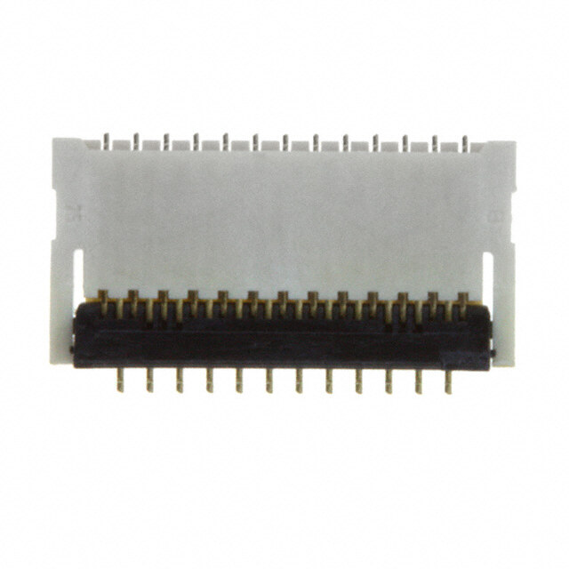
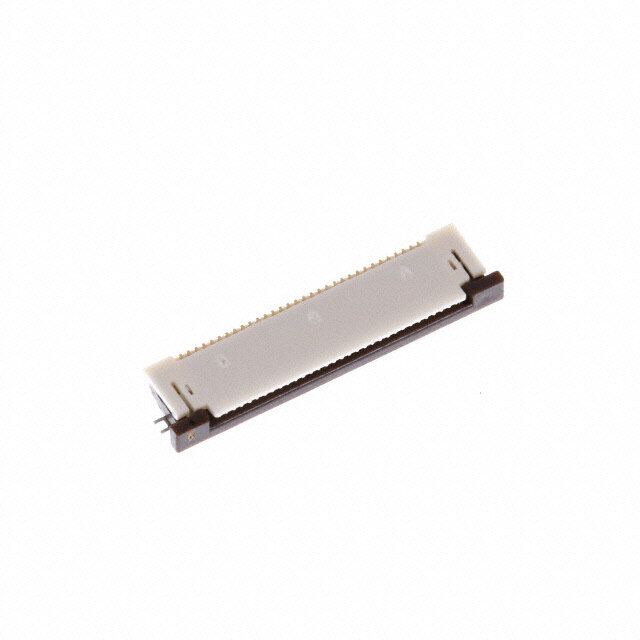
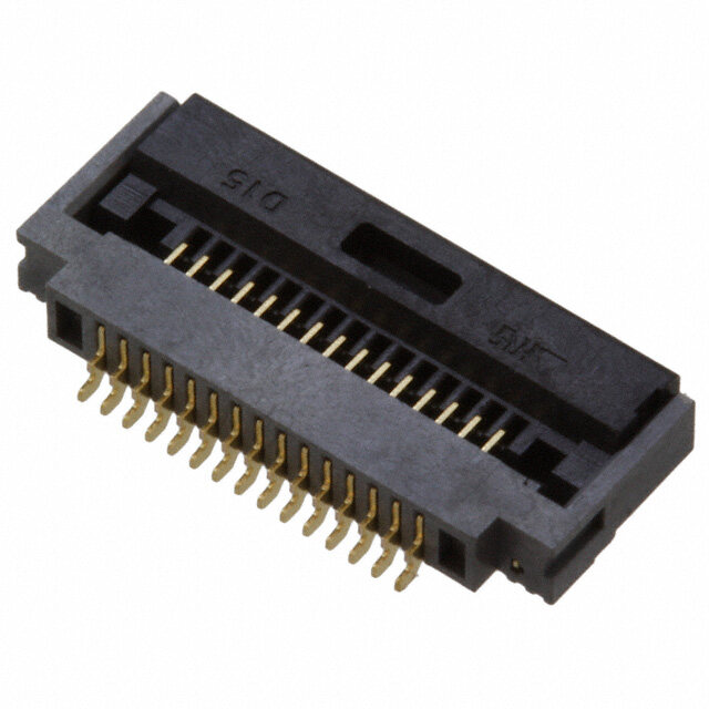
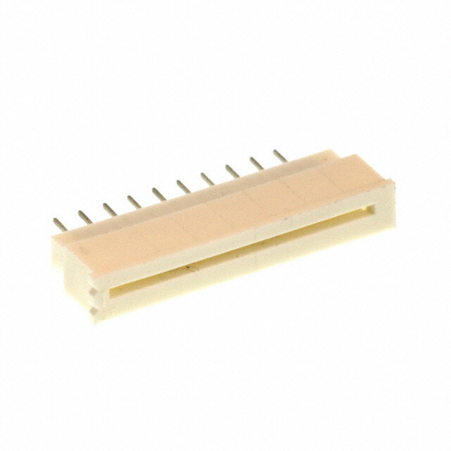
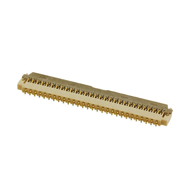
ICGOO电子元器件商城为您提供FH39-27S-0.3SHW(10)由Hirose Electric设计生产,在icgoo商城现货销售,并且可以通过原厂、代理商等渠道进行代购。 FH39-27S-0.3SHW(10)价格参考¥7.06-¥12.33。Hirose ElectricFH39-27S-0.3SHW(10)封装/规格:FFC,FPC(扁平柔性)连接器, 27 位置 FPC 连接器 触头,上和下 0.012"(0.30mm) 表面贴装,直角。您可以下载FH39-27S-0.3SHW(10)参考资料、Datasheet数据手册功能说明书,资料中有FH39-27S-0.3SHW(10) 详细功能的应用电路图电压和使用方法及教程。
| 参数 | 数值 |
| 产品目录 | |
| 描述 | CONN FPC 27POS .3MM SMD |
| 产品分类 | |
| FFC,FCB厚度 | 0.20mm |
| 品牌 | Hirose Electric Co Ltd |
| 数据手册 | |
| 产品图片 |
|
| 产品型号 | FH39-27S-0.3SHW(10) |
| rohs | 无铅 / 符合限制有害物质指令(RoHS)规范要求 |
| 产品系列 | FH39 |
| 产品培训模块 | http://www.digikey.cn/PTM/IndividualPTM.page?site=cn&lang=zhs&ptm=25293 |
| 产品目录绘图 |
|
| 产品目录页面 | |
| 其它名称 | HFU27DKR |
| 包装 | Digi-Reel® |
| 外壳材料 | 液晶聚合物(LCP) |
| 安装类型 | 表面贴装,直角 |
| 工作温度 | -55°C ~ 85°C |
| 扁平柔性类型 | FPC |
| 材料可燃性等级 | UL94 V-0 |
| 板上高度 | 0.044"(1.10mm) |
| 标准包装 | 1 |
| 特性 | 零插入力(ZIF) |
| 特色产品 | http://www.digikey.com/product-highlights/cn/zh/hirose-fh39-series-fpc-connectors/2421 |
| 电缆端类型 | 锥形 |
| 端接 | |
| 致动器材料 | 聚酰胺(PA),尼龙 |
| 触头材料 | 磷青铜 |
| 触头镀层 | 金 |
| 连接器/触头类型 | 触头,上和下 |
| 针脚数 | 27 |
| 锁定功能 | 翻转锁定,背锁 |
| 间距 | 0.012"(0.30mm) |
| 额定电压 | 30V |
| 额定电流 | 0.2A |
.JPG)


.jpg)

.jpg)

- 商务部:美国ITC正式对集成电路等产品启动337调查
- 曝三星4nm工艺存在良率问题 高通将骁龙8 Gen1或转产台积电
- 太阳诱电将投资9.5亿元在常州建新厂生产MLCC 预计2023年完工
- 英特尔发布欧洲新工厂建设计划 深化IDM 2.0 战略
- 台积电先进制程称霸业界 有大客户加持明年业绩稳了
- 达到5530亿美元!SIA预计今年全球半导体销售额将创下新高
- 英特尔拟将自动驾驶子公司Mobileye上市 估值或超500亿美元
- 三星加码芯片和SET,合并消费电子和移动部门,撤换高东真等 CEO
- 三星电子宣布重大人事变动 还合并消费电子和移动部门
- 海关总署:前11个月进口集成电路产品价值2.52万亿元 增长14.8%
.jpg)
.jpg)
PDF Datasheet 数据手册内容提取
0.3mm Pitch 1.1mm Height Top and Bottom Contact Back-Flip actuator Flexible Printed Circuit Connectors FH39 Series ●3.45mm Depth 1.1mm d. e eserv 13.9mm(39 pos.) m m s R 3.45 ht g Ri All Fig.1 D. O., LT ■Features ●Easy FPC insertion 1. Low-profi le 0.3mm pitch connector with C C top and bottom contact RI Usable via either its top or bottom contact point, T AAccttuuaattoorr C this connector achieves enhanced freedom in terms E L of the product design. E E 2. High contact reliability thanks to the S O spring terminal structure R HI Because both top and bottom contact points are 8 spring-loaded, the contact point adapts to the FPC 1 0 motion, and high contact reliability is ensured. FFPPCC 2 ht 3. Delivered with the actuator open g yri FPC can be immediately inserted without the need for p o the opening of the actuator. (Fig.2) Fig.2 C 8 4. Easy FPC insertion 1 ●Completely locked 0 Entry chamfers at all sides of the FPC insertion slot 2 1. assure correct insertion and positioning of the FPC. c. e D 5. Accepts standard FPC thickness 0.2mm thick standard Flexible Printed Circuit (FPC) can be used. This is the only ultra-low profi le ZIF connector using standard FPC. 6. Conductive traces on the PCB can run under the connector No exposed contacts on the bottom of the connector. 7. Board placement with automatic equipment Flat upper surface and tape and reel packaging facilitate vacuum pick-up and placement. Fig.3 Standard reel packaging contains 5000 connectors. 8. Halogen-free* (FH39J Series) *As defi ned by IEC61249-2-21 Br-900ppm maximum, Cl-900ppm maximum, Cl + Br combined-1,500ppm maximum 2015.8③ 1
FH39 Series●0.3mm Pitch 1.1mm Height Top and Bottom Contact Back-Flip actuator Flexible Printed Circuit Connectors ■Product Specifi cations Operating Storage Current rating 0.2A -55 to +85°C (Note 1) -10 to +50°C (Note 2) temperature range temperature range Ratings Operating Relative humidity 90% max. Storage Relative humidity 90% max. Voltage rating 30Vrms AC humidity range (No condensation) humidity range (No condensation) Recommended FPC Thickness: 0.2 ± 0.03mm, Gold plated contact pads Item Specifi cation Conditions 1.Insulation resistance 50Mø min. 100V DC 2.Withstanding voltage No fl ashover or insulation breakdown 90Vrms AC / 1 minute 100mø max. 3.Contact resistance 1mA, AC max (AC: 1kHz) d. * Including FPC and FFC conductor resistance e Contact resistance : 100mø max. v 4.Durability 10 cycles er No damage, cracks, or parts dislocation s e No electrical discontinuity of 1µs or longer Frequency : 10 to 55Hz, R s 5.Vibration Contact resistance : 100mø max. single amplitude of 0.75mm, ht No damage, cracks, or parts dislocation 10 cycles in each of the 3 axis g Ri No electrical discontinuity of 1µs or longer Acceleration of 981m/s2, 6ms duration, All 6.Shock CNoon dtaacmt aregsei,s ctarancckes :, 1o0r 0pmarøts m daisxlo. cation sine half-wave, 3 cycles in each of the 3 axis D. Contact resistance : 100mø max. T 7.Humidity L Insulation resistance : 50Mø min. 96 hours at 40ç and humidity of 90 to 95% O., (Steady state) No damage, cracks, or parts dislocation C Contact resistance : 100mø max. Temperature : -55ç➝+15ç to +35ç➝+85ç➝+15ç to +35ç C 8.Temperature cycle Insulation resistance : 50Mø min. Time : 30➝ 2 to 3 ➝ 30➝ 2 to 3 minutes RI No damage, cracks, or parts dislocation 5 cycles T C 9. Resistance to No deformation of components affecting Refl ow : At the recommended temperature profi le E L soldering heat performance Manual soldering : 350ç ± 5ç for 5 seconds E E Note 1 : Includes temperature rise caused by current fl ow. S Note 2 : The term "storage" refers to products stored for a long period prior to mounting and use. O R The operating temperature and humidity range covers the non-conducting condition of installed connectors HI in storage, shipment or during transportation after board mounting. 8 01 ■Materials / Finish 2 ht g Part Material Finish Remarks ri y LCP Color:Beige op Insulator UL94V-0 C PA Color:Black 8 Contacts Gold plated ----------------- 1 Phosphor bronze 0 Metal fi ttings Pure tin refl ow plated ----------------- 2 1. c. e D ■Product Number Structure FH 39 J - 51S - 0.3 SHW (10) q w e r t y u qSeries name : FH rNo. of Contacts wSeries No. : 39 FH39 :25 to 61 eBlank :Standard FH39A :67 A :Long actuator type FH39J :25 to 51 J :Halogen-free (Flame retardance UL94V-0). tContact pitch : 0.3mm yTermination type SHW...S MT horizontal staggered row mount type uPlating specifi cations (10)...Standard 5,000 pcs/reel (99)...500 pcs/reel 2
FH39 Series●0.3mm Pitch 1.1mm Height Top and Bottom Contact Back-Flip actuator Flexible Printed Circuit Connectors ■ Connector Dimensions A±0.15 0.3±0.1 B±0.1 0.6±0.1 (0.12) 2 0. ± 1.85) 3.55 ( d. Production LOT No. e 0.6±0.1 (0.12) v er C±0.1 s e B R s ht g Ri All (0.15) D. (D) (0.6) T E±0.1 (3.3) L O., B Detailed drawing B Detailed drawing C [FH39 Series] [FH39A Series] C (3.85) (4.15) ROSE ELECTRI 0.42)(FPC : t 0.2mm) (2.(11).55(0).85) (90˚)1.1±0.1(1.54) 0.42)(FPC : t 0.2mm) (2.(11).5(50).85) (90˚) 1.1±0.1(1.89) HI 0.4(7±0.1 0.3±0.1 0.4(7±0.1 0.3±0.1 8 0.1±0.15 3.25±0.15 0.1±0.15 0.1±0.15 3.25±0.15 0.1±0.15 1 1 0.1 1 0.1 1 0.1 1 0.1 0 2 ht g ri Note 1 : The coplanarity of each terminal lead within specifi ed dimension is 0.1 mm Max. y p 2 : Packaged on tape and reel only. Check packaging specifi cation. o C 3 : Slight variations in color of the plastic compounds do not affect form, fi t or function of the connector. 8 4 : After refl ow, the terminal plating may change color, however this does not represent a quality issue. 1 0 2 1. All dimensions : mm c. e Part No. HRS No. No. of Contacts A B C D E D FH39-25S-0.3SHW(10) 580-1806-8 10 25 9.7 6.6 7.2 7.83 9.15 FH39-27S-0.3SHW(10) 580-1805-5 10 27 10.3 7.2 7.8 8.43 9.75 FH39-29S-0.3SHW(10) 580-1807-0 10 29 10.9 7.8 8.4 9.03 10.35 FH39-33S-0.3SHW(10) 580-1803-0 10 33 12.1 9 9.6 10.23 11.55 FH39-39S-0.3SHW(10) 580-1800-1 10 39 13.9 10.8 11.4 12.03 13.35 FH39-45S-0.3SHW(10) 580-1802-7 10 45 15.7 12.6 13.2 13.83 15.15 FH39-51S-0.3SHW(10) 580-1801-4 10 51 17.5 14.4 15 15.63 16.95 FH39-61S-0.3SHW(10) 580-1808-3 10 61 20.5 17.4 18 18.63 19.95 FH39A-67S-0.3SHW(10) 580-1809-6 10 67 22.3 19.2 19.8 20.43 21.75 FH39J-25S-0.3SHW(10) 580-1815-9 10 25 9.7 6.6 7.2 7.83 9.15 FH39J-33S-0.3SHW(10) 580-1814-6 10 33 12.1 9 9.6 10.23 11.55 FH39J-39S-0.3SHW(10) 580-1813-3 10 39 13.9 10.8 11.4 12.03 13.35 FH39J-45S-0.3SHW(10) 580-1811-8 10 45 15.7 12.6 13.2 13.83 15.15 FH39J-51S-0.3SHW(10) 580-1812-0 10 51 17.5 14.4 15 15.63 16.95 Note 1:Tape and reel packaging (5,000 pcs/reel, 500 pcs/reel). Note 2:Order by number of reels. 3
FH39 Series●0.3mm Pitch 1.1mm Height Top and Bottom Contact Back-Flip actuator Flexible Printed Circuit Connectors BRecommended PCB mounting pattern and metal mask dimensions 2) 4 k:0. B±0.05 Recommended s metal mask thickness : t=0.1 05 ma 0.3±0.03 0.6±0.05 0.5±0. (Metal (Metal mask:0.25) (0.1) (0.2) 1) k: 5 s 0 a (3.65) 2.48±0. 0.3±0.05 1±0.05 (Metal m d. e v Rights Reser 0.67±0.05 Metal mask:0.57) (0M.3e±ta0l. 0m3ask:0.2C5)±0.05 0.6±0.05 0.(8M0±.e30t5.a0±l5 0m.0a5sk:0.35)0.1±0.05 All ( D. B Recommended FPC Dimensions T L O., F±0.05 C 0.3±0.07 C±0.03 0.3±0.07 C 0.3+0.04 0.6±0.02 0.2±0.03 TRI 2- -0.03 0.3±0.02 0.1 ±0.1 ±0.1 C R0.2 3± 05 15 E 0. 1. 1. L E a) HIROSE 2.1±0.1 2.25±0.1 2.65±0.3 ncovered are MIN (Stiffner) 8 (U 65 201 0.3+-00..0043 00..12 ∞(1) 3. ht 0.1±0.02 * g ri y p 0.6±0.07 B±0.03 0.6±0.07 o C 8 Note : Stiffener dimension should be 3.65mm min., however if it is not satisfi ed, X dimension should be 0.5mm or more. 1 0 2 1. c. All dimensions : mm e D Part No. HRS No. No. of Contacts B C F FH39-25S-0.3SHW(10) 580-1806-8 10 25 6.6 7.2 7.8 FH39-27S-0.3SHW(10) 580-1805-5 10 27 7.2 7.8 8.4 FH39-29S-0.3SHW(10) 580-1807-0 10 29 7.8 8.4 9 FH39-33S-0.3SHW(10) 580-1803-0 10 33 9 9.6 10.2 FH39-39S-0.3SHW(10) 580-1800-1 10 39 10.8 11.4 12 FH39-45S-0.3SHW(10) 580-1802-7 10 45 12.6 13.2 13.8 FH39-51S-0.3SHW(10) 580-1801-4 10 51 14.4 15 15.6 FH39-61S-0.3SHW(10) 580-1808-3 10 61 17.4 18 18.6 FH39A-67S-0.3SHW(10) 580-1809-6 10 67 19.2 19.8 20.4 FH39J-25S-0.3SHW(10) 580-1815-9 10 25 6.6 7.2 7.8 FH39J-33S-0.3SHW(10) 580-1814-6 10 33 9 9.6 10.2 FH39J-39S-0.3SHW(10) 580-1813-3 10 39 10.8 11.4 12 FH39J-45S-0.3SHW(10) 580-1811-8 10 45 12.6 13.2 13.8 FH39J-51S-0.3SHW(10) 580-1812-0 10 51 14.4 15 15.6 4
FH39 Series●0.3mm Pitch 1.1mm Height Top and Bottom Contact Back-Flip actuator Flexible Printed Circuit Connectors BRecommended FPC construction 1. Using Single-sided FPC FPC : Flexible Printed Circuit Material Name Material Material Thickness(µm) Covering fi lm layer Polyimide 1 mil thick. (25) Cover adhesive (25) Surface treatment 0.2µm thick gold plated over 1 to 5µm 3 nickel underplating Copper foil Cu 1oz 35 Base adhesive Thermosetting adhesive 25 Base fi lm Polyimide 1 mil thick 25 Reinforcement material adhesive Thermosetting adhesive 40 d. Stiffener Polyimide 3 mil thick 75 e v Total 203 r e es 2. Using Double-sided FPC FPC : Flexible Printed Circuit R s ht Material Name Material Material Thickness (µm) g Ri Covering fi lm layer Polyimide 1 mil thick. (25) All Cover adhesive (25) D. Surface treatment 0.2µm thick gold plated over 1 to 5µm 3 nickel underplating T L Through-hole copper Cu 15 O., Copper foil Cu 1/2oz 18 C Base adhesive Thermosetting adhesive 18 C RI Base fi lm Polyimide 1 mil thick 25 T Base adhesive Thermosetting adhesive 18 C E Copper foil Cu 1/2oz (18) L E Cover adhesive Thermosetting adhesive 25 E S Covering fi lm layer Polyimide 1 mil thick. 25 O Reinforcement material adhesive Thermosetting adhesive 25 R HI Stiffener Polyimide 3 mil thick 25 8 Total 197 1 0 2 * T o prevent release of the FPC due to its bending, use of the double sided FPC with copper foil on the back side is not recommended. ht g 3. Precautions ri y p o 1 : This specifi cation is a recommendation for the construction of the FH39 Series FPC (t=0.2±0.03). C 8 2 : For details about the construction, please contact the FPC manufacturers. 1 0 BPackaging Specifi cation 2 c.1. ● Embossed Carrier Tape Dimensions (Tape width to 24mm max.) e D (2.1 : FH39 series) 4±0.1 2±0.15 8±0.1 1 ((02..34) : FH39A series) Ø1.5 + 0 .01 1.75±0. 1 0. ± J 3 K) 0. ( ± G Flat surface, for placement with automatic equipment. (4.65) Unreeling direction (1.85) 5
FH39 Series●0.3mm Pitch 1.1mm Height Top and Bottom Contact Back-Flip actuator Flexible Printed Circuit Connectors ● Embossed Carrier Tape Dimensions (Tape width 32mm min.) Ø1.5 + 0 .01 75±0.1 1. 1 0. ± J K) ( 1 3 0. 0. ± ± H G d. e v r e s e R s ht g Ri All LTD. 1.5+ 00.1 +0.15 0 O., 1.7 C ●Reel Dimensions C 13) (L : INSIDE) RI (Ø T C E L E E HIROS (Ø380) (Ø80) 8 1 0 2 ht g (M : OUTSIDE) ri y p Co All dimensions : mm 8 Part No. HRS No. No. of Contacts G H J K L M 1 0 FH39-25S-0.3SHW(10) 580-1806-8 10 25 --- 11 2 1. FH39-27S-0.3SHW(10) 580-1805-5 10 27 --- 11.6 c. e FH39-29S-0.3SHW(10) 580-1807-0 10 29 24 --- 11.5 12.2 25.4 29.4 D FH39-33S-0.3SHW(10) 580-1803-0 10 33 --- 13.4 FH39-39S-0.3SHW(10) 580-1800-1 10 39 --- 15.2 FH39-45S-0.3SHW(10) 580-1802-7 10 45 17 32 28.4 14.2 33.4 37.4 FH39-51S-0.3SHW(10) 580-1801-4 10 51 18.8 FH39-61S-0.3SHW(10) 580-1808-3 10 61 21.8 44 40.4 20.2 45.4 49.4 FH39A-67S-0.3SHW(10) 580-1809-6 10 67 23.6 FH39J-25S-0.3SHW(10) 580-1815-9 10 25 --- 11 FH39J-33S-0.3SHW(10) 580-1814-6 10 33 24 --- 11.5 13.4 25.4 29.4 FH39J-39S-0.3SHW(10) 580-1813-3 10 39 --- 15.2 FH39J-45S-0.3SHW(10) 580-1811-8 10 45 17 32 28.4 14.2 33.4 37.4 FH39J-51S-0.3SHW(10) 580-1812-0 10 51 18.8 6
FH39 Series●0.3mm Pitch 1.1mm Height Top and Bottom Contact Back-Flip actuator Flexible Printed Circuit Connectors BConnector Operation and Precautions Operation Exercise care when handling connectors. Follow recommendations given below. 1. As delivered TThhee aaccttuuaattoorr iiss ooppeenn wwhheenn ddeelliivveerreedd iinn Delivered with the actuator open. There is no need to tthhee eemmbboosssseedd ttaappee ppaacckkaaggiinngg operate the actuator prior to the insertion of the FPC. [Note] •Do not close the actuator if the FPC has not been inserted yet. d. •If the actuator is closed without the FPC, it can narrow the e v contact gap and increases the insertion force. r e s e R 2. FPC insertion s ht Align the FPC perpendicular with the connector and insert g Ri it fi rmly all the way. All D. T L O., C C RI T C 3. Locking method E L qOperate the actuator in a E E rotational manner and press S it down. O R Rotate and push down on the HI RRoottaattee middle portion or the entire 8 EExxcceessssiivvee ffoorrccee aafftteerr tthhee aaccttuuaattoorr iiss aallrreeaaddyy cclloosseedd 1 width of the actuator using the 0 2 fi nger tip. ht Be sure to distribute the g ri pressure evenly across the y p actuator, pressing down on only o C one side of the actuator may 8 damage the actuator. Excessive 1 force on the housing can also 0 1.2 lead to damage or malfunction. PPuusshh aatt tthhee cceenntteerr ooff tthhee aaccttuuaattoorr.. DDoo NNOOTT cclloossee aatt tthhee eennddss.. c. e D 4. FPC removal (Lock release) qSlowly rotate the actuator in an upward motion. After it is RRoottaattee ((lliifftt)) unlocked, the FPC can be removed. DDoo nnoott aatttteemmpptt ttoo ooppeenn mmoorree tthhaann 9900°° wWhen unlocking the actuator, always touch the middle portion of the actuator. Again, be sure to distribute the pressure evenly across the actuator, pressing down on only one side may damage the actuator. The actuator has a maximum opening of 90ç. LLiifftt aatt tthhee cceenntteerr DDoo nnoott ooppeenn ((lliifftt)) aatt oonnee eenndd.. Trying to open it more than that or applying any unnecessary force to the actuator will cause damage and possibly failure of the connector. * The actuator opens by rotating it in the direction opposite to the direction of the insertion of the FPC. do not attempt to open it from the same side as the insertion of the FPC. 7
FH39 Series●0.3mm Pitch 1.1mm Height Top and Bottom Contact Back-Flip actuator Flexible Printed Circuit Connectors Precautions when mounting connectors on the PCB ◆ PC board warpage Minimize the warpage as much as possible. The connector is straight within 0.1 mm max. Make sure that the mounting area fl atness can accept the connector terminals without causing any failure of the solder joints. ◆ Handling before mounting on PCB Do not apply 0.5N or more external force to the connector before mounting. Insertion of the FPC or operation of the actuator prior to mounting on the PCB is not recommended. ◆ Forces on the board When braking the large PC board into individual boards exercise care not to damage the installed connectors. When attaching the boards or other components with the screws make sure that any stresses will not ed. cause board defl ections affecting the mounting areas of the connector. rv Connector e s e R FPC (for mounting connectors) s ht g Ri All D. T L O., Other precautions C ◆ When hand soldering: C • Do not perform hand soldering with the FPC inserted in the connector. RI T • Do not apply excessive heat or touch the soldering iron anywhere other than the connector leads. C E • Do not use excessive amount of solder or fl ux compounds. L E Operation of the actuator or contacts may be affected by excessive amounts of solder or E fl ux compounds. S O R HI 8 BTemperature Profi le 1 0 2 HRS test condition ht MAX 250ç Solder method :Refl ow, IR/hot air g yri 250 Environment :Room air p o 230ç Solder composition :Paste, C 18 (ç) 200 200ç 9 6.5%Sn/3.0%Ag/0.( 5S%enCjuu Metal Industry, Co., Ltd.'s 0 1.2 ure Part No.:M705-221CM5-32-10.5) Dec. mperat 150 150ç Test board :G2 5lamsms ∞ep5o0xmym ∞0.8mm thick e T Land dimensions :0 .3mm∞0.5mm, 100 0.3mm∞0.67mm Metal mask :0 .25∞0.42, 0.25∞0.57∞0.1mm thick 50 The temperature profi les shown are based on the above 25ç (60 sec.) 90 sec. to 120 sec. (60 sec.) conditions. Preheating Soldering 0 In individual applications the actual temperature may vary, Start depending on solder paste type, volume / thickness and Time (Seconds) board size / thickness. Consult your solder paste and equipment manufacturer for specifi c recommendations. ® 2-6-3,Nakagawa Chuoh,Tsuzuki-Ku,Yokohama-Shi 224-8540,JAPAN TEL: +81-45-620-3526 Fax: +81-45-591-3726 http://www.hirose.com http://www.hirose-connectors.com The characteristics and the specifications contained herein are for reference purpose. Please refer to the latest customer drawings prior to use. 8 The contents of this catalog are current as of date of 08/2015. Contents are subject to change without notice for the purpose of improvements. Powered by TCPDF (www.tcpdf.org)
Mouser Electronics Authorized Distributor Click to View Pricing, Inventory, Delivery & Lifecycle Information: H irose Electric: FH39-25S-0.3SHW(10) FH39-27S-0.3SHW(10) FH39-29S-0.3SHW(10) FH39-33S-0.3SHW(10) FH39-39S- 0.3SHW(10) FH39-45S-0.3SHW(10) FH39-51S-0.3SHW(10) FH39A-67S-0.3SHW(10) FH39-61S-0.3SHW(10) FH39J-23S-0.3SHW(10) FH39J-25S-0.3SHW(10) FH39J-33S-0.3SHW(10) FH39J-39S-0.3SHW(10) FH39J-45S- 0.3SHW(10) FH39J-51S-0.3SHW(10) FH39-27S-0.3SHW(99) FH39-25S-0.3SHW(99) FH39-45S-0.3SHW(99) FH39J-39S-0.3SHW(99) FH39-61S-0.3SHW(99) FH39J-27S-0.3SHW(99) FH39-33S-0.3SHW(99) FH39J-23S- 0.3SHW(99) FH39J-27S-0.3SHW(10) FH39J-33S-0.3SHW(99) FH39J-45S-0.3SHW(99) FH39J-25S-0.3SHW(99) FH39-39S-0.3SHW(99) FH39J-51S-0.3SHW(99) FH39-51S-0.3SHW(99) FH39-29S-0.3SHW(99) FH39A-67S- 0.3SHW(99)