ICGOO在线商城 > 连接器,互连器件 > FFC,FPC(扁平柔性)连接器 > FH35C-37S-0.3SHW(99)
- 型号: FH35C-37S-0.3SHW(99)
- 制造商: Hirose Electric
- 库位|库存: xxxx|xxxx
- 要求:
| 数量阶梯 | 香港交货 | 国内含税 |
| +xxxx | $xxxx | ¥xxxx |
查看当月历史价格
查看今年历史价格
FH35C-37S-0.3SHW(99)产品简介:
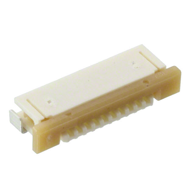
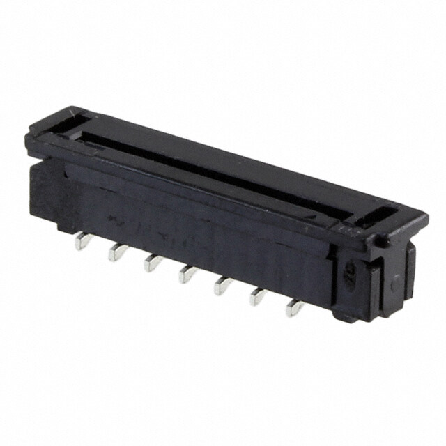
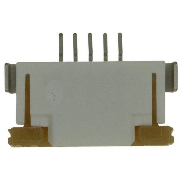
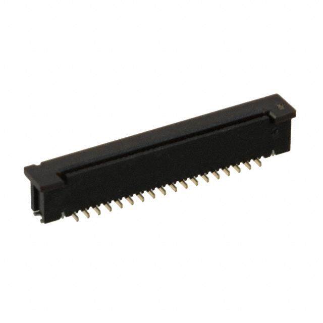
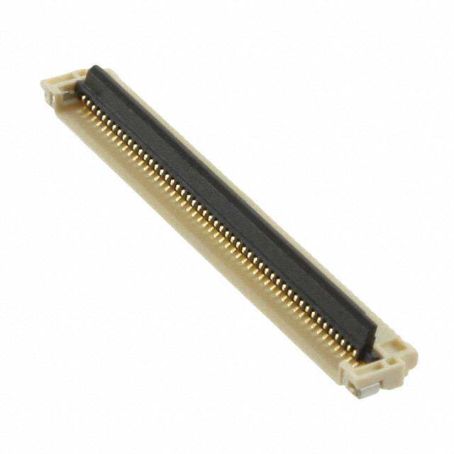
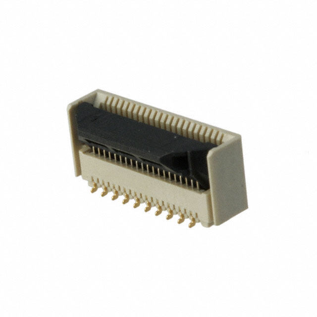
ICGOO电子元器件商城为您提供FH35C-37S-0.3SHW(99)由Hirose Electric设计生产,在icgoo商城现货销售,并且可以通过原厂、代理商等渠道进行代购。 FH35C-37S-0.3SHW(99)价格参考。Hirose ElectricFH35C-37S-0.3SHW(99)封装/规格:FFC,FPC(扁平柔性)连接器, 37 位置 FPC 连接器 触头,上和下 0.012"(0.30mm) 表面贴装,直角。您可以下载FH35C-37S-0.3SHW(99)参考资料、Datasheet数据手册功能说明书,资料中有FH35C-37S-0.3SHW(99) 详细功能的应用电路图电压和使用方法及教程。
| 参数 | 数值 |
| 产品目录 | |
| 描述 | CONN FPC 37POS .3MM GOLD SMDFFC & FPC连接器 37P BCKFLP DUAL-SIDE FPC 0.3mm P 0.9mm H |
| 产品分类 | |
| FFC,FCB厚度 | 0.20mm |
| 品牌 | Hirose Connector |
| 产品手册 | |
| 产品图片 | |
| rohs | 符合RoHS无铅 / 符合限制有害物质指令(RoHS)规范要求 |
| 产品系列 | FFC & FPC连接器,Hirose Connector FH35C-37S-0.3SHW(99)FH35C |
| 数据手册 | |
| 产品型号 | FH35C-37S-0.3SHW(99) |
| 产品种类 | FFC & FPC连接器 |
| 产品类型 | Board Mount |
| 位置数量 | 37 |
| 其它名称 | H122276DKR |
| 包装 | Digi-Reel® |
| 商标 | Hirose Connector |
| 外壳材料 | Liquid Crystal Polymer (LCP) |
| 安装类型 | 表面贴装,直角 |
| 安装角 | Right |
| 封装 | Reel |
| 工作温度 | -55°C ~ 85°C |
| 工厂包装数量 | 500 |
| 扁平柔性类型 | FPC |
| 材料可燃性等级 | UL94 V-0 |
| 板上高度 | 0.036"(0.90mm) |
| 标准包装 | 1 |
| 温度范围 | - 55 C to + 85 C |
| 特性 | - |
| 电压额定值 | 30 VAC |
| 电流额定值 | 0.2 A |
| 电缆端类型 | 锥形 |
| 端接 | |
| 端接类型 | SMD |
| 系列 | FH35C |
| 绝缘电阻 | 50 MOhms |
| 联系位置 | Dual Contact |
| 致动器材料 | 聚酰胺(PA),尼龙 |
| 节距 | 0.3 mm |
| 触头材料 | 磷青铜 |
| 触头镀层 | 金 |
| 触点材料 | Phosphor Bronze |
| 触点电镀 | Gold |
| 连接器/触头类型 | 触头,上和下 |
| 针脚数 | 37 |
| 锁定功能 | 翻转锁定,背锁 |
| 间距 | 0.012"(0.30mm) |
| 额定电压 | 30V |
| 额定电流 | 0.2A |




- 商务部:美国ITC正式对集成电路等产品启动337调查
- 曝三星4nm工艺存在良率问题 高通将骁龙8 Gen1或转产台积电
- 太阳诱电将投资9.5亿元在常州建新厂生产MLCC 预计2023年完工
- 英特尔发布欧洲新工厂建设计划 深化IDM 2.0 战略
- 台积电先进制程称霸业界 有大客户加持明年业绩稳了
- 达到5530亿美元!SIA预计今年全球半导体销售额将创下新高
- 英特尔拟将自动驾驶子公司Mobileye上市 估值或超500亿美元
- 三星加码芯片和SET,合并消费电子和移动部门,撤换高东真等 CEO
- 三星电子宣布重大人事变动 还合并消费电子和移动部门
- 海关总署:前11个月进口集成电路产品价值2.52万亿元 增长14.8%
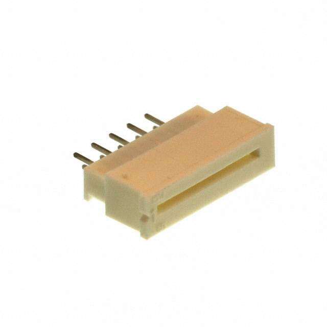
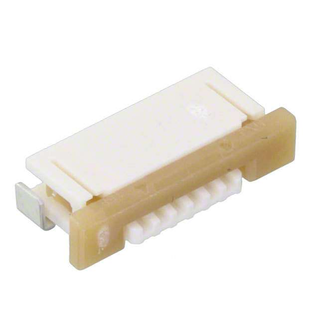
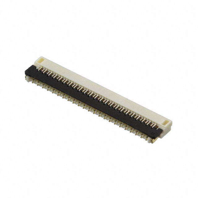
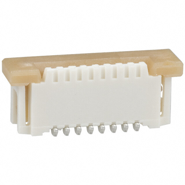
PDF Datasheet 数据手册内容提取
0.3 mm pitch, 0.9 mm height, back flip type dual-sided FPC connector FH35C Series ● 3.2 mm in depth (cid:98) (cid:98) (cid:46) (cid:37)(cid:35) ved. (cid:38)(cid:39)(cid:35)(cid:38)(cid:21)(cid:98)(cid:98)(cid:29)(cid:40)(cid:42)(cid:21)(cid:101)(cid:94)(cid:99)(cid:30) (cid:40)(cid:35)(cid:39)(cid:98)(cid:98) r e s e R s ■Features ht g Ri 1. 0.3 mm pitch, Dual-sided connector All This connector utilizes both a top and bottom contact ● At Time of FPC Insertion D. and provides design flexibility. T O., L 2. Iumsep roofv eodu rF pPrCo prreiteetnatriyo nc ofnotraccet ascthruiecvtuerde tahnrodu ag hb athcke C C flip actuator. RI FPC retention force (in the horizontal direction) is about 2.5 T C times greater than similar products produced by other E companies. L E E 3. Supports high speed transmissions S O By utilizing its excellent impedance characteristics, it is R capable of supporting high speed transmissions. HI (Differential pairs of identical contacts allows for better 8 transmission characteristics and eDP (ver1.3) and 1 0 compatibility to MIPI(D−PHY) specifications.) 2 ht 4. Delivered with actuator open ● Lock Completion State g ri To reduce installation time and costs, the actuator is y p delivered in the open position and eliminates the need to o C open the actuator before FPC insertion. 8 1 5. Easy FPC Insertion 0 2 Equipped with tapered guides at the FPC insertions point, 1. c. they help to create a smoother FPC insertion operation. e D 6. Compatible with 0.2mm thick FPC The FH35C was designed to be used with 0.2 mm FPC. (Using the appropriate FPC will prevent deformation and problems that may occur during the insertion and mating processes.) 7. Bottom side protection The bottom surface is over-molded and provides added protection to the contacts (no exposure). This allows the FH35C Differential Impedance PCB space under the connector to be used for additional 130ps rise time (20-80%) patterning. 8. Halogen Free Chlorine and bromine levels do not exceed the standard values as defined by IEC 61249-2-21. (Br: 900 ppm or less, Cl : 900 ppm or less, Br + Cl : 1,500 ppm or less) 9. Compatible with Automatic Mounting Tape-and-reel packaging is available for use with pick-and- place machines. Connectors are available on 5000 or 500 piece reels. (The outer diameter of an embossed reel is Ø180mm) In cases where the application will demand a high level of reliability, such as automotive, please contact a company representative for further information. 2013.11② 1
FH35C Series●0.3 mm pitch, 0.9 mm height, back flip type dual-sided FPC connector ■Product Specifications Operating temperature Range: –55 to Storage temperature Range: -10 to +50°C +85°C (Note 2) (Note 3) Current rating: 0.2 A (Note 1) Ratings Operating temperature Range: 90% or less Storage temperature Range: 90% or less Voltage rating: AC 30 Vrms of relative humidity of relative humidity (No dew condensation is allowed) (No dew condensation is allowed) With specifi cations compatible with FPC contacts t = 0.2 ± 0.03 gold plating Items Specifi cations Conditions 1.Insulation Resistance No less than 50 Mø Measured at 100 V DC 2.Withstand Voltage No fl ashover or breakdown Conduct 90 V AC for one minute 100 mø MAX. 3.Contact Resistance AC 20 mV MAX (1 KHz), 1 mA * Including FPC conductor resistance d. 4.Mating Cycles Contact resistance: no more than 100 mø 10 times e No breakage, cracks, or loosened parts v er No electric outage of 1 µs or greater At the frequency of 10-55 Hz, half amplitude es 5.Vibration Resistance Contact resistance: no more than 100 mø 0.75 mm, and 10 cycles in each of three axial R No breakage, cracks, or loosened parts directions s ht No electric outage of 1 µs or greater Acceleration: 981 m/s2 Rig 6.Shock Resistance Contact resistance: no more than 100 mø Duration: 6 ms, sine half-wave, 3 cycles in each All No breakage, cracks, or loosened parts of the 3 axis each in both directions D. 7. Humidity Resistance CInosnutlaactito rne Rsiestsaisntcaen:c neo: 5m0o Mreø t hoar nm 1o0re0 mø Left to stand for 96 hours at the temperature of T (Steady State) 40°C and the humidity of 90% to 95% L No breakage, cracks, or loosened parts O., Contact resistance: no more than 100 mø Temperature:-55➝ +15 to+35➝ +85➝ +15 to C +35°C C 8.Temperature Cycles Insulation Resistance: 50 Mø or more Time: 30➝ 2 to 3 ➝ 30➝ 2 to 3 minutes RI No breakage, cracks, or loosened parts 5 cycles with the above conditions T C 9. Solder Heat No deformation in appearance or marked Refl ow: According to the Recommended Temperature E Profi le L Resistance instability of contacts E Manual soldering: 350± 10°C for 5± 1 sec. E (Note 1) Use at 70% of the current rating when all pins are energized with the stated current rating. S O (Note 2) Temperature rise at the time of electrifi cation is included. R (Note 3) T he term “storage” refers to the long-term storage condition of unused products before mounting on the PCB. HI The operating temperature and humidity ranges apply to non-energized state after PCB mounting. 8 (Note 4) The above specifications are representative of this series. Please refer to “drawing for approval” for official individual 1 0 agreement. 2 ht g ■Materials ri y p o Part Materials Treatment UL Regulation C 8 LCP Gray 1 Insulator UL94V-0 0 Polyamide resin Black 2 1. Contact Phosphor bronze Nickel barrier Gold plating c. ------ e Metal fi tting Phosphor bronze Pure tin refl ow plating D ■Product Number Structure Refer to the chart below when searching for the part number nomenclature. Please select connectors listed in this catalog when placing orders. The characteristics and specifications of the products described in this catalog are for reference only. Please make sure to check the latest delivery specifications before the time of purchase. FH 35 C − 35S − 0.3 SHW (50) ❶ ❷ ❸ ❹ ❺ ❻ ❼ ❶ Series Name: FH ❻ Contact Form ❷ Series No.: 35 SHW: SMT horizontal staggered array mount type ❸ C: dual-sided, halogen-free product ❼ Specifi cations: ❹ Number of contacts : 9 to 51 (50): standard product (5000 connectors per reel) ❺ Contact Pitch: 0.3 mm (99): 500 connectors per reel 2
FH35C Series●0.3 mm pitch, 0.9 mm height, back flip type dual-sided FPC connector ■Connector Dimensions (cid:54)(cid:164)(cid:37)(cid:35)(cid:38)(cid:42) (cid:37)(cid:35)(cid:40)(cid:164)(cid:37)(cid:35)(cid:38) (cid:55)(cid:164)(cid:37)(cid:35)(cid:38) (cid:37)(cid:35)(cid:43)(cid:164)(cid:37)(cid:35)(cid:38) (cid:29)(cid:37)(cid:35)(cid:38)(cid:39)(cid:30) (cid:42)(cid:30) (cid:40) (cid:40)(cid:35) (cid:43)(cid:30) (cid:29) (cid:38)(cid:35) (cid:29) (cid:37)(cid:35)(cid:43)(cid:164)(cid:37)(cid:35)(cid:38) (cid:29)(cid:37)(cid:35)(cid:38)(cid:39)(cid:30) (cid:56)(cid:164)(cid:37)(cid:35)(cid:38) (cid:57)(cid:94)(cid:104)(cid:101)(cid:97)(cid:86)(cid:110)(cid:21)(cid:100)(cid:91)(cid:21)(cid:105)(cid:93)(cid:90) (cid:57)(cid:94)(cid:104)(cid:101)(cid:97)(cid:86)(cid:110)(cid:90)(cid:89) d. (cid:99)(cid:106)(cid:98)(cid:87)(cid:90)(cid:103)(cid:21)(cid:100)(cid:91)(cid:21)(cid:88)(cid:100)(cid:103)(cid:90)(cid:104) (cid:56)(cid:86)(cid:107)(cid:94)(cid:105)(cid:110)(cid:21)(cid:67)(cid:100)(cid:35) (cid:61)(cid:71)(cid:72)(cid:21)(cid:98)(cid:86)(cid:103)(cid:96) (cid:69)(cid:100)(cid:97)(cid:86)(cid:103)(cid:94)(cid:105)(cid:110)(cid:21)(cid:98)(cid:86)(cid:103)(cid:96) ve (cid:86) r e s e R s ht (cid:29)(cid:37)(cid:35)(cid:38)(cid:42)(cid:30) g Ri (cid:29)(cid:57)(cid:30) (cid:29)(cid:37)(cid:35)(cid:43)(cid:30) All (cid:58)(cid:164)(cid:37)(cid:35)(cid:38) (cid:29)(cid:40)(cid:30) D. T (cid:86)(cid:21)(cid:57)(cid:90)(cid:105)(cid:86)(cid:94)(cid:97)(cid:21)(cid:89)(cid:103)(cid:86)(cid:108)(cid:94)(cid:99)(cid:92) (cid:29)(cid:41)(cid:35)(cid:39)(cid:30) L CO., (cid:39) (cid:29)(cid:38)(cid:29)(cid:35)(cid:38)(cid:41)(cid:35)(cid:42)(cid:38)(cid:29)(cid:30)(cid:42)(cid:37)(cid:30)(cid:35)(cid:42)(cid:42)(cid:30) (cid:29)(cid:46)(cid:37)(cid:233)(cid:30) C (cid:37)(cid:35) TRI (cid:59)(cid:69)(cid:56)(cid:47) (cid:37)(cid:35)(cid:38) (cid:29)(cid:38)(cid:35)(cid:45)(cid:30) C (cid:164) LE (cid:37)(cid:35)(cid:40)(cid:42)(cid:30) (cid:37)(cid:35)(cid:46) E E (cid:29) (cid:37)(cid:35)(cid:41)(cid:164)(cid:37)(cid:35)(cid:38) (cid:37)(cid:35)(cid:40)(cid:40)(cid:164)(cid:37)(cid:35)(cid:38) S (cid:37)(cid:35)(cid:37)(cid:42)(cid:164)(cid:37)(cid:35)(cid:38)(cid:42) (cid:40)(cid:164)(cid:37)(cid:35)(cid:38)(cid:42) (cid:37)(cid:35)(cid:38)(cid:42)(cid:164)(cid:37)(cid:35)(cid:38)(cid:42) O R Note 1: The lead coplanarity of contact and reinforcing metal fi tting is a MAX of 0.1 mm. HI 2: This product packaged on tape-and-reel. See the package specifi cation diagram for details. 8 1 3: Dimensions may be changed for sink mark prevention due to improvement, etc. 0 2 In addition, black dots, etc., may occur in the mold resin but they have no effect on quality. ht 4: This product is halogen-free. g ri (Br content: 900 ppm or less; CI content: 900 ppm or less; Br + CL total content: 1,500 ppm or less) y p o C 8 1 20 ■Connector Dimension Table Unit: mm 1. c. e Product No. HRS No. The number of contacts A B C D E D FH35C-9S-0.3SHW(50) CL580-2910-5-50 9 4.3 1.8 2.4 3.03 3.73 FH35C-11S-0.3SHW(50) CL580-2917-4-50 11 4.9 2.4 3 3.63 4.33 FH35C-13S-0.3SHW(50) CL580-2925-2-50 13 5.5 3 3.6 4.23 4.93 FH35C-15S-0.3SHW(50) CL580-2919-0-50 15 6.1 3.6 4.2 4.83 5.53 FH35C-17S-0.3SHW(50) CL580-2916-1-50 17 6.7 4.2 4.8 5.43 6.13 FH35C-19S-0.3SHW(50) CL580-2921-1-50 19 7.3 4.8 5.4 6.03 6.73 FH35C-21S-0.3SHW(50) CL580-2922-4-50 21 7.9 5.4 6 6.63 7.33 FH35C-23S-0.3SHW(50) CL580-2911-8-50 23 8.5 6 6.6 7.23 7.93 FH35C-25S-0.3SHW(50) CL580-2912-0-50 25 9.1 6.6 7.2 7.83 8.53 FH35C-27S-0.3SHW(50) CL580-2918-7-50 27 9.7 7.2 7.8 8.43 9.13 FH35C-31S-0.3SHW(50) CL580-2923-7-50 31 10.9 8.4 9 9.63 10.33 FH35C-33S-0.3SHW(50) CL580-2913-3-50 33 11.5 9 9.6 10.23 10.93 FH35C-35S-0.3SHW(50) CL580-2926-5-50 35 12.1 9.6 10.2 10.83 11.53 FH35C-37S-0.3SHW(50) CL580-2914-6-50 37 12.7 10.2 10.8 11.43 12.13 FH35C-39S-0.3SHW(50) CL580-2915-9-50 39 13.3 10.8 11.4 12.03 12.73 FH35C-41S-0.3SHW(50) CL580-2924-0-50 41 13.9 11.4 12 12.63 13.33 FH35C-45S-0.3SHW(50) CL580-2909-6-50 45 15.1 12.6 13.2 13.83 14.53 FH35C-49S-0.3SHW(50) ––––––– 49 16.3 13.8 14.4 15.03 15.73 FH35C-51S-0.3SHW(50) CL580-2920-9-50 51 16.9 14.4 15 15.63 16.33 The products with no HRS No. are currently under planning. Please contact our sales representative for questions concerning the number of contacts. 3
FH35C Series●0.3 mm pitch, 0.9 mm height, back flip type dual-sided FPC connector ■Recommended Land Dimensions (cid:40) (cid:55) (cid:37)(cid:35)(cid:43)(cid:42)(cid:164)(cid:37)(cid:35)(cid:37) (cid:29)(cid:37)(cid:35)(cid:40)(cid:42)(cid:30) (cid:29)(cid:37)(cid:35)(cid:39)(cid:30) (cid:37)(cid:35)(cid:43) (cid:37)(cid:35)(cid:40)(cid:164)(cid:37)(cid:35)(cid:37)(cid:39) (cid:29)(cid:56)(cid:100)(cid:99)(cid:29)(cid:99)(cid:29)(cid:99)(cid:90)(cid:34)(cid:88)(cid:38)(cid:105)(cid:100)(cid:30)(cid:37)(cid:36)(cid:103)(cid:35)(cid:39)(cid:21)(cid:37)(cid:94)(cid:30)(cid:98)(cid:39)(cid:20)(cid:86)(cid:92)(cid:77)(cid:90)(cid:21)(cid:172)(cid:66)(cid:100)(cid:106)(cid:99)(cid:105)(cid:90)(cid:89)(cid:21)(cid:104)(cid:106)(cid:103)(cid:91)(cid:86)(cid:88)(cid:90)(cid:30) (cid:40) (cid:37) (cid:29)(cid:40)(cid:35)(cid:43)(cid:30) (cid:38)(cid:42)(cid:164)(cid:37)(cid:35)(cid:37)(cid:40) (cid:37)(cid:35)(cid:46)(cid:42)(cid:164)(cid:37)(cid:35) (cid:39)(cid:35) (cid:40) (cid:29)(cid:29)(cid:99)(cid:32)(cid:38)(cid:30)(cid:36)(cid:39)(cid:30)(cid:20) (cid:40) (cid:37)(cid:35)(cid:37) (cid:37)(cid:35)(cid:40)(cid:164)(cid:37)(cid:35)(cid:37)(cid:39) (cid:37)(cid:35)(cid:37)(cid:39) (cid:77) (cid:37)(cid:35)(cid:37) (cid:164) (cid:37)(cid:35)(cid:43) (cid:164) (cid:45) (cid:39) d. (cid:37)(cid:35) (cid:37)(cid:35)(cid:41)(cid:164)(cid:37)(cid:35)(cid:37)(cid:40) (cid:37)(cid:35) e (cid:56) (cid:37)(cid:35)(cid:42)(cid:164)(cid:37)(cid:35)(cid:37)(cid:40) v (cid:77) r e s e ■Recommended Land and Metal Mask Dimensions R ghts (cid:37)(cid:35)(cid:37)(cid:39) (cid:55) (cid:29)(cid:71)(cid:90)(cid:88)(cid:100)(cid:98)(cid:98)(cid:90)(cid:99)(cid:89)(cid:90)(cid:89)(cid:21)(cid:66)(cid:90)(cid:105)(cid:86)(cid:97)(cid:21)(cid:66)(cid:86)(cid:104)(cid:96)(cid:21)(cid:73)(cid:93)(cid:94)(cid:88)(cid:96)(cid:99)(cid:90)(cid:104)(cid:104)(cid:47)(cid:21)(cid:105)(cid:21)(cid:50)(cid:21)(cid:37)(cid:35)(cid:38)(cid:30) Ri (cid:42)(cid:164) (cid:37)(cid:35)(cid:43) (cid:37)(cid:35)(cid:39)(cid:40)(cid:164)(cid:37)(cid:35)(cid:37)(cid:39) (cid:29)(cid:29)(cid:99)(cid:34)(cid:38)(cid:30)(cid:36)(cid:39)(cid:30)(cid:20) All (cid:37)(cid:35)(cid:42) (cid:37)(cid:35)(cid:37)(cid:39) (cid:78) D. (cid:29)(cid:65)(cid:86)(cid:99)(cid:89)(cid:21)(cid:101)(cid:86)(cid:105)(cid:105)(cid:90)(cid:103)(cid:99)(cid:21)(cid:94)(cid:98)(cid:86)(cid:92)(cid:90)(cid:30) T CO., L (cid:29)(cid:40)(cid:35)(cid:43)(cid:30) (cid:39)(cid:35)(cid:41)(cid:164)(cid:37)(cid:35)(cid:37)(cid:39) (cid:37)(cid:35)(cid:44)(cid:164)(cid:37)(cid:35)(cid:37)(cid:39) C RI ELECT (cid:37)(cid:35)(cid:43)(cid:42)(cid:164)(cid:37)(cid:35)(cid:37)(cid:39) (cid:37)(cid:35)(cid:43) (cid:37)(cid:35)(cid:39)(cid:40)(cid:164)(cid:37)(cid:35)(cid:37)(cid:39) (cid:29)(cid:37)(cid:29)(cid:99)(cid:35)(cid:40)(cid:32)(cid:164)(cid:38)(cid:37)(cid:37)(cid:30)(cid:35)(cid:35)(cid:36)(cid:37)(cid:37)(cid:39)(cid:39)(cid:39)(cid:30)(cid:20) (cid:78) (cid:37)(cid:35)(cid:39)(cid:164)(cid:37)(cid:35)(cid:37)(cid:39) E (cid:56) (cid:37)(cid:35)(cid:46)(cid:164)(cid:37)(cid:35)(cid:37)(cid:39) S (cid:78) O R Note 5: 'n' represents the number of contacts. HI 8 1 0 2 ht g ri y ■Recommended Land and Metal Mask Dimensions p Unit: mm o C Product No. HRS No. No. of Contacts B C 8 1 FH35C-9S-0.3SHW(50) CL580-2910-5-50 9 1.8 2.4 0 2 FH35C-11S-0.3SHW(50) CL580-2917-4-50 11 2.4 3 1. FH35C-13S-0.3SHW(50) CL580-2925-2-50 13 3 3.6 c. e FH35C-15S-0.3SHW(50) CL580-2919-0-50 15 3.6 4.2 D FH35C-17S-0.3SHW(50) CL580-2916-1-50 17 4.2 4.8 FH35C-19S-0.3SHW(50) CL580-2921-1-50 19 4.8 5.4 FH35C-21S-0.3SHW(50) CL580-2922-4-50 21 5.4 6 FH35C-23S-0.3SHW(50) CL580-2911-8-50 23 6 6.6 FH35C-25S-0.3SHW(50) CL580-2912-0-50 25 6.6 7.2 FH35C-27S-0.3SHW(50) CL580-2918-7-50 27 7.2 7.8 FH35C-31S-0.3SHW(50) CL580-2923-7-50 31 8.4 9 FH35C-33S-0.3SHW(50) CL580-2913-3-50 33 9 9.6 FH35C-35S-0.3SHW(50) CL580-2926-5-50 35 9.6 10.2 FH35C-37S-0.3SHW(50) CL580-2914-6-50 37 10.2 10.8 FH35C-39S-0.3SHW(50) CL580-2915-9-50 39 10.8 11.4 FH35C-41S-0.3SHW(50) CL580-2924-0-50 41 11.4 12 FH35C-45S-0.3SHW(50) CL580-2909-6-50 45 12.6 13.2 FH35C-49S-0.3SHW(50) ––––––– 49 13.8 14.4 FH35C-51S-0.3SHW(50) CL580-2920-9-50 51 14.4 15 4
FH35C Series●0.3 mm pitch, 0.9 mm height, back flip type dual-sided FPC connector ■Recommended FPC Dimensions (cid:59)(cid:164)(cid:37)(cid:35)(cid:37)(cid:42) (cid:37)(cid:35)(cid:39)(cid:164)(cid:37)(cid:35)(cid:37)(cid:40) (cid:56) (cid:79) (cid:37)(cid:35)(cid:40)(cid:164)(cid:37)(cid:35)(cid:37)(cid:44) (cid:37)(cid:35)(cid:40)(cid:164)(cid:37)(cid:35)(cid:37)(cid:44) (cid:29)(cid:29)(cid:99)(cid:32)(cid:38)(cid:30)(cid:36)(cid:39)(cid:30)(cid:20) (cid:37)(cid:35)(cid:43) (cid:37)(cid:35)(cid:40)(cid:32)(cid:34)(cid:37)(cid:37)(cid:35)(cid:35)(cid:37)(cid:37)(cid:40)(cid:41) (cid:37)(cid:35)(cid:37)(cid:39) (cid:79) (cid:37)(cid:35)(cid:40) (cid:38) (cid:38) (cid:38) (cid:66)(cid:54)(cid:77)(cid:21) (cid:164)(cid:37)(cid:35) (cid:164)(cid:37)(cid:35) (cid:164)(cid:37)(cid:35) (cid:71)(cid:37)(cid:35)(cid:39) (cid:87) (cid:37)(cid:35)(cid:39) (cid:37)(cid:35)(cid:44)(cid:42) (cid:37)(cid:35)(cid:45)(cid:42) (cid:98)(cid:30) eserved. (cid:29)(cid:66)(cid:71)(cid:94)(cid:90)(cid:104)(cid:86)(cid:91)(cid:90)(cid:97)(cid:94)(cid:103)(cid:92)(cid:90)(cid:99)(cid:99)(cid:98)(cid:88)(cid:90)(cid:90)(cid:21)(cid:99)(cid:92)(cid:105)(cid:90)(cid:21)(cid:88)(cid:100)(cid:93)(cid:98)(cid:90)(cid:90)(cid:88)(cid:96)(cid:105)(cid:103)(cid:21)(cid:110)(cid:29)(cid:37)(cid:35)(cid:42)(cid:30)(cid:29)(cid:38)(cid:35)(cid:39)(cid:42)(cid:30)(cid:98)(cid:30)(cid:86)(cid:103)(cid:96) (cid:38)(cid:35)(cid:44)(cid:42)(cid:164)(cid:37)(cid:35)(cid:40) (cid:39)(cid:35)(cid:38)(cid:164)(cid:37)(cid:35)(cid:38) (cid:39)(cid:35)(cid:39)(cid:42)(cid:164)(cid:37)(cid:35)(cid:38) (cid:42)(cid:164)(cid:37)(cid:35)(cid:40)(cid:21)(cid:29)(cid:72)(cid:105)(cid:94)(cid:91)(cid:91)(cid:90)(cid:99)(cid:90)(cid:103)(cid:21)(cid:91)(cid:94)(cid:97) R (cid:45) s (cid:39)(cid:35) ht (cid:67) g Ri D. All (cid:29)(cid:37)(cid:35)(cid:37)(cid:44)(cid:30) (cid:29)(cid:37)(cid:37)(cid:35)(cid:39)(cid:35)(cid:38)(cid:30)(cid:164)(cid:37)(cid:35)(cid:37)(cid:39) (cid:55) (cid:37)(cid:35)(cid:40)(cid:32)(cid:34)(cid:37)(cid:37)(cid:35)(cid:35)(cid:37)(cid:37)(cid:40)(cid:41) (cid:29)(cid:29)(cid:99)(cid:34)(cid:38)(cid:30)(cid:37)(cid:36)(cid:39)(cid:35)(cid:37)(cid:30)(cid:20)(cid:39) (cid:79) T (cid:37)(cid:35)(cid:43)(cid:164)(cid:37)(cid:35)(cid:37)(cid:44) (cid:37)(cid:35)(cid:43)(cid:164)(cid:37)(cid:35)(cid:37)(cid:44) L O., C Note 6: FPC should be designed so that the dimension of N is 0.5 mm or more. C RI T C E L E E S O R HI 8 1 0 2 ht g ri y ■Recommended FPC Dimensions p Unit: mm o C Product No. HRS No. No. of Contacts B C F 8 1 FH35C-9S-0.3SHW(50) CL580-2910-5-50 9 1.8 2.4 3 0 2 FH35C-11S-0.3SHW(50) CL580-2917-4-50 11 2.4 3 3.6 1. FH35C-13S-0.3SHW(50) CL580-2925-2-50 13 3 3.6 4.2 c. e FH35C-15S-0.3SHW(50) CL580-2919-0-50 15 3.6 4.2 4.8 D FH35C-17S-0.3SHW(50) CL580-2916-1-50 17 4.2 4.8 5.4 FH35C-19S-0.3SHW(50) CL580-2921-1-50 19 4.8 5.4 6 FH35C-21S-0.3SHW(50) CL580-2922-4-50 21 5.4 6 6.6 FH35C-23S-0.3SHW(50) CL580-2911-8-50 23 6 6.6 7.2 FH35C-25S-0.3SHW(50) CL580-2912-0-50 25 6.6 7.2 7.8 FH35C-27S-0.3SHW(50) CL580-2918-7-50 27 7.2 7.8 8.4 FH35C-31S-0.3SHW(50) CL580-2923-7-50 31 8.4 9 9.6 FH35C-33S-0.3SHW(50) CL580-2913-3-50 33 9 9.6 10.2 FH35C-35S-0.3SHW(50) CL580-2926-5-50 35 9.6 10.2 10.8 FH35C-37S-0.3SHW(50) CL580-2914-6-50 37 10.2 10.8 11.4 FH35C-39S-0.3SHW(50) CL580-2915-9-50 39 10.8 11.4 12 FH35C-41S-0.3SHW(50) CL580-2924-0-50 41 11.4 12 12.6 FH35C-45S-0.3SHW(50) CL580-2909-6-50 45 12.6 13.2 13.8 FH35C-49S-0.3SHW(50) ––––––– 49 13.8 14.4 15 FH35C-51S-0.3SHW(50) CL580-2920-9-50 51 14.4 15 15.6 5
FH35C Series●0.3 mm pitch, 0.9 mm height, back flip type dual-sided FPC connector BFPC material composition (Recommended specifications) 1.Single-Sided FPC Name of material Material property Thickness (µm) Cover lay film Polyimide 1 mil (25) Cover adhesive (25) Nickel undercoat 1 to 5µm+ Surface treatment Gold plating 0.2µm 3 Copper foil Cu 1 oz 35 Base adhesive Heat hardened adhesive 25 d. Base film Polyimide 1 mil 25 e v Reinforcement material adhesive Heat hardened adhesive 40 r e s Stiffener film Polyimide 3 mil 75 e R Total 203 s ht g Ri All D. 2.Double-Sided FPC T L O., Name of material Material property Thickness (µm) C C Cover lay film Polyimide 1 mil (25) RI Cover adhesive (25) T C E Surface treatment Nickel undercoat 1 to 5 µm+ L Gold plating 0.2 µm 3 E E Through-hole copper plating Cu 15 S O Copper foil Cu ½ oz 18 R HI Base adhesive Thermoset adhesive 18 8 Base film Polyimide 1 mil 25 1 0 Base adhesive Thermoset adhesive 18 2 ht Copper foil Cu ½ oz (18) g yri Cover adhesive Thermoset adhesive 25 p o Cover lay film Polyimide 1 mil 25 C 8 Reinforcement material adhesive Thermoset adhesive 25 1 0 Stiffener film Polyimide 1 mil 25 2 1. Total 197 c. e * When using Double-Sided FPC, the copper foil on the back side of the FPC should be eliminated. This is to prevent any unintentional D unlocking due to bent or deformed FPC. 3.Additional notes on FPC 1. T he FPC material composition is to be used as a reference example. Please make sure that the thickness of the FPC mating area is 0.2± 0.03 mm as previously referred to in the product specification section. 2. Please contact the FPC manufacturer for the details on its material composition. 6
FH35C Series●0.3 mm pitch, 0.9 mm height, back flip type dual-sided FPC connector BPackaging Specifications ● Emboss Carrier Tape Dimensions ● Emboss Carrier Tape Dimensions (with tape width of 24 mm or less) (with tape width of 32 mm or more) (cid:29)(cid:39)(cid:35)(cid:39)(cid:42)(cid:30) (cid:45)(cid:164)(cid:37)(cid:35)(cid:38) (cid:38) (cid:29)(cid:29)(cid:37)(cid:39)(cid:35)(cid:35)(cid:40)(cid:39)(cid:30)(cid:42)(cid:30) (cid:41)(cid:29)(cid:164)(cid:39)(cid:30)(cid:37)(cid:35)(cid:38) (cid:45)(cid:164)(cid:37)(cid:35)(cid:38) (cid:162)(cid:38)(cid:35)(cid:42)(cid:32)(cid:37)(cid:35)(cid:38)(cid:37)(cid:21) (cid:38)(cid:35)(cid:44)(cid:42)(cid:164)(cid:37)(cid:35)(cid:38) (cid:29)(cid:37)(cid:35)(cid:40)(cid:30) (cid:41)(cid:29)(cid:164)(cid:39)(cid:30)(cid:37)(cid:35)(cid:38) (cid:162)(cid:38)(cid:35)(cid:42)(cid:32)(cid:37)(cid:35)(cid:37)(cid:38)(cid:21) (cid:38)(cid:35)(cid:44)(cid:42)(cid:164)(cid:37)(cid:35) (cid:38) (cid:37)(cid:35)(cid:38) (cid:164)(cid:37)(cid:35) (cid:63)(cid:164)(cid:164)(cid:37)(cid:35)(cid:40) (cid:63)(cid:164)(cid:37)(cid:35)(cid:38)(cid:164)(cid:37)(cid:35)(cid:40) (cid:60) (cid:61)(cid:60) ed. (cid:71) (cid:37)(cid:35)(cid:44)(cid:42)(cid:30) v (cid:29) r e s hts Re (cid:74)(cid:99)(cid:103)(cid:90)(cid:90)(cid:97)(cid:94)(cid:99)(cid:92)(cid:21)(cid:89)(cid:94)(cid:103)(cid:90)(cid:88)(cid:105)(cid:94)(cid:100)(cid:99) (cid:29)(cid:71)(cid:37)(cid:35)(cid:44)(cid:42)(cid:30) (cid:38)(cid:35)(cid:42)(cid:32)(cid:37)(cid:37)(cid:35)(cid:38)(cid:21)(cid:32)(cid:37)(cid:35)(cid:38)(cid:42)(cid:38)(cid:35)(cid:44)(cid:21)(cid:21)(cid:21)(cid:37) g Ri ●Packaging Specification Dimensions All D. T L (cid:40)(cid:30)(cid:21) (cid:29)(cid:64)(cid:47)(cid:21)(cid:71)(cid:90)(cid:90)(cid:97)(cid:21)(cid:62)(cid:99)(cid:99)(cid:90)(cid:103)(cid:21)(cid:76)(cid:94)(cid:89)(cid:105)(cid:93)(cid:30) O., (cid:29)(cid:162)(cid:38) (cid:41)(cid:37)(cid:37)(cid:21)(cid:98)(cid:98)(cid:21)(cid:100)(cid:103)(cid:21)(cid:98)(cid:100)(cid:103)(cid:90) C (cid:29)(cid:65)(cid:90)(cid:86)(cid:89)(cid:90)(cid:103)(cid:21)(cid:54)(cid:103)(cid:90)(cid:86)(cid:30) C ECTRI (cid:29)(cid:162)(cid:40)(cid:45)(cid:37)(cid:30) (cid:29)(cid:162)(cid:45)(cid:37)(cid:30) L E E (cid:38)(cid:43)(cid:37)(cid:98)(cid:98)(cid:21)(cid:100)(cid:103)(cid:21)(cid:98)(cid:100)(cid:103)(cid:90) (cid:58)(cid:98)(cid:87)(cid:100)(cid:104)(cid:104)(cid:21)(cid:56)(cid:86)(cid:103)(cid:103)(cid:94)(cid:90)(cid:103)(cid:21)(cid:73)(cid:86)(cid:101)(cid:90) (cid:38)(cid:37)(cid:37)(cid:98)(cid:98)(cid:21)(cid:100)(cid:103)(cid:21)(cid:98)(cid:100)(cid:103)(cid:90) (cid:73)(cid:100)(cid:101)(cid:21)(cid:56)(cid:100)(cid:107)(cid:90)(cid:103)(cid:21)(cid:73)(cid:86)(cid:101)(cid:90) S (cid:29)(cid:65)(cid:47)(cid:21)(cid:71)(cid:90)(cid:90)(cid:97)(cid:21)(cid:68)(cid:106)(cid:105)(cid:90)(cid:103)(cid:21)(cid:76)(cid:94)(cid:89)(cid:105)(cid:93)(cid:30) (cid:29)(cid:73)(cid:103)(cid:86)(cid:94)(cid:97)(cid:90)(cid:103)(cid:21)(cid:86)(cid:103)(cid:90)(cid:86)(cid:36)(cid:90)(cid:98)(cid:101)(cid:105)(cid:110)(cid:21)(cid:86)(cid:103)(cid:90)(cid:86)(cid:30) (cid:21)(cid:29)(cid:58)(cid:98)(cid:101)(cid:105)(cid:110)(cid:21)(cid:86)(cid:103)(cid:90)(cid:86)(cid:30) O R HI 8 1 0 2 ht g ri y p ■Reel Dimensions o Unit: mm C 8 Product No. HRS No. No. of Contacts G H J K L 1 FH35C-9S-0.3SHW(50) CL580-2910-5-50 9 16 - 7.5 17.4 21.4 0 2 FH35C-11S-0.3SHW(50) CL580-2917-4-50 11 16 - 7.5 17.4 21.4 1. c. FH35C-13S-0.3SHW(50) CL580-2925-2-50 13 16 - 7.5 17.4 21.4 e FH35C-15S-0.3SHW(50) CL580-2919-0-50 15 16 - 7.5 17.4 21.4 D FH35C-17S-0.3SHW(50) CL580-2916-1-50 17 16 - 7.5 17.4 21.4 FH35C-19S-0.3SHW(50) CL580-2921-1-50 19 16 - 7.5 17.4 21.4 FH35C-21S-0.3SHW(50) CL580-2922-4-50 21 24 - 11.5 25.4 29.4 FH35C-23S-0.3SHW(50) CL580-2911-8-50 23 24 - 11.5 25.4 29.4 FH35C-25S-0.3SHW(50) CL580-2912-0-50 25 24 - 11.5 25.4 29.4 FH35C-27S-0.3SHW(50) CL580-2918-7-50 27 24 - 11.5 25.4 29.4 FH35C-31S-0.3SHW(50) CL580-2923-7-50 31 24 - 11.5 25.4 29.4 FH35C-33S-0.3SHW(50) CL580-2913-3-50 33 24 - 11.5 25.4 29.4 FH35C-35S-0.3SHW(50) CL580-2926-5-50 35 24 - 11.5 25.4 29.4 FH35C-37S-0.3SHW(50) CL580-2914-6-50 37 24 - 11.5 25.4 29.4 FH35C-39S-0.3SHW(50) CL580-2915-9-50 39 24 - 11.5 25.4 29.4 FH35C-41S-0.3SHW(50) CL580-2924-0-50 41 24 - 11.5 25.4 29.4 FH35C-45S-0.3SHW(50) CL580-2909-6-50 45 24 - 11.5 25.4 29.4 FH35C-49S-0.3SHW(50) - 49 32 28.4 14.2 33.4 37.4 FH35C-51S-0.3SHW(50) CL580-2920-9-50 51 32 28.4 14.2 33.4 37.4 7
FH35C Series●0.3 mm pitch, 0.9 mm height, back flip type dual-sided FPC connector ■Temperature Profile (cid:66)(cid:54)(cid:77)(cid:21)(cid:39)(cid:42)(cid:37)(cid:149)(cid:56)(cid:238) Applicable Conditions (cid:39)(cid:42)(cid:37) Reflow System : Far-infrared, hot-air reflow (cid:39)(cid:40)(cid:37)(cid:149)(cid:56)(cid:238) Reflow chamber atmosphere : Air Solder :Paste type Sn/3.0 Ag/0.5 Cu (cid:56)(cid:30)(cid:21) (cid:39)(cid:37)(cid:37) (cid:39)(cid:37)(cid:37)(cid:149)(cid:56)(cid:238) (M705-GRN360-K2-V; (cid:106)(cid:103)(cid:90)(cid:21)(cid:29)(cid:149) Test PCB :SPeCnBju m Maetetarila Iln adnuds tsriyz eCo., Ltd.) (cid:90)(cid:103)(cid:86)(cid:105) (cid:38)(cid:42)(cid:37) Glass epoxy 25 × 50 × 0.8 mm (cid:101) (cid:38)(cid:42)(cid:37)(cid:149)(cid:56)(cid:238) (cid:98) Land dimensions (cid:90) (cid:73) 0.3 × 0.65, 0.3 × 0.8 mm d. (cid:38)(cid:37)(cid:37) Metal Mask :Thickness : 0.1 mm e Opening dimension v r 0.23 × 0.55, 0.23 × 0.65 mm e s e (cid:42)(cid:37) The provided temperature profile shown is based on the R s (cid:39)(cid:42)(cid:149)(cid:56)(cid:238) conditions described above. ht (cid:29)(cid:43)(cid:37)(cid:21)(cid:104)(cid:90)(cid:88)(cid:35)(cid:30) (cid:46)(cid:37)(cid:21)(cid:105)(cid:100)(cid:21)(cid:38)(cid:39)(cid:37)(cid:21)(cid:104)(cid:90)(cid:88)(cid:35)(cid:21) (cid:29)(cid:43)(cid:37)(cid:21)(cid:104)(cid:90)(cid:88)(cid:35)(cid:30)(cid:21) Variations may occur due to the changing conditions such Rig (cid:37) (cid:21)(cid:21)(cid:69)(cid:103)(cid:90)(cid:93)(cid:90)(cid:86)(cid:105)(cid:94)(cid:99)(cid:92)(cid:21)(cid:105)(cid:94)(cid:98)(cid:90) (cid:21)(cid:72)(cid:100)(cid:97)(cid:89)(cid:90)(cid:103)(cid:94)(cid:99)(cid:92)(cid:21)(cid:105)(cid:94)(cid:98)(cid:90) as solder paste types, different manufacturers, PCB size, All (cid:72)(cid:105)(cid:86)(cid:103)(cid:105) aconndd oittihoenrs sboelfdoerrein ugs em.aterials. Please check the mounting D. (cid:73)(cid:94)(cid:98)(cid:90)(cid:21)(cid:29)(cid:104)(cid:90)(cid:88)(cid:100)(cid:99)(cid:89)(cid:104)(cid:30) T L O., C C RI T C E L E E S O R HI 8 1 0 2 ht g ri y p o C 8 1 0 2 1. c. e D 8
FH35C Series●0.3 mm pitch, 0.9 mm height, back flip type dual-sided FPC connector BConnector Handling and Precautions [Operational Method] These connectors are small and thin, so care needs to be used when handling this product. Please refer to this section after confirming the following points: 1. Initial mounted status (before inserting FPC) (cid:73)(cid:73)(cid:93)(cid:93)(cid:90)(cid:90)(cid:21)(cid:21)(cid:86)(cid:86)(cid:88)(cid:88)(cid:105)(cid:105)(cid:106)(cid:106)(cid:86)(cid:86)(cid:105)(cid:105)(cid:100)(cid:100)(cid:103)(cid:103)(cid:21)(cid:21)(cid:94)(cid:94)(cid:104)(cid:104)(cid:21)(cid:21)(cid:104)(cid:104)(cid:106)(cid:106)(cid:101)(cid:101)(cid:101)(cid:101)(cid:97)(cid:97)(cid:94)(cid:94)(cid:90)(cid:90)(cid:89)(cid:89)(cid:21)(cid:21)(cid:94)(cid:94)(cid:99)(cid:99)(cid:21)(cid:21)(cid:105)(cid:105)(cid:93)(cid:93)(cid:90)(cid:90)(cid:21)(cid:21)(cid:100)(cid:100)(cid:101)(cid:101)(cid:90)(cid:90)(cid:99)(cid:99)(cid:21)(cid:21)(cid:88)(cid:88)(cid:100)(cid:100)(cid:99)(cid:99)(cid:89)(cid:89)(cid:94)(cid:94)(cid:105)(cid:105)(cid:94)(cid:94)(cid:100)(cid:100)(cid:99)(cid:99)(cid:21)(cid:21)(cid:94)(cid:94)(cid:99)(cid:99) (cid:105)(cid:105)(cid:93)(cid:93)(cid:90)(cid:90)(cid:21)(cid:21)(cid:90)(cid:90)(cid:98)(cid:98)(cid:87)(cid:87)(cid:100)(cid:100)(cid:104)(cid:104)(cid:104)(cid:104)(cid:90)(cid:90)(cid:89)(cid:89)(cid:21)(cid:21)(cid:105)(cid:105)(cid:86)(cid:86)(cid:101)(cid:101)(cid:90)(cid:90)(cid:21)(cid:21)(cid:86)(cid:86)(cid:99)(cid:99)(cid:89)(cid:89)(cid:21)(cid:21)(cid:103)(cid:103)(cid:90)(cid:90)(cid:90)(cid:90)(cid:97)(cid:97)(cid:21)(cid:21)(cid:101)(cid:101)(cid:86)(cid:86)(cid:88)(cid:88)(cid:96)(cid:96)(cid:86)(cid:86)(cid:92)(cid:92)(cid:94)(cid:94)(cid:99)(cid:99)(cid:92)(cid:92)(cid:35)(cid:35) ❶ These connectors are delivered with the actuator in an open position,removing the need to operate the actuator before inserting the FPC. [Caution] d. (cid:129) Do not close the actuator if the FPC has not been inserted yet. e v (cid:129) If the actuator is closed without the FPC, it can narrow the contact r e s gap and increases the insertion force. e R s ht 2. FPC insertion method g Ri ❶ Ensure that the FPC is held parallel to the surface of the PCB and is then completely inserted into the All connector. D. T L [Caution] O., (cid:129) Do not insert the FPC if actuator is closed. C (cid:129) If the actuator is closed and if the FPC is twisted during insertion, it can cause contact deformation and / or C contact failure. RI T C (cid:54)(cid:88)(cid:105)(cid:106)(cid:86)(cid:105)(cid:100)(cid:103)(cid:21)(cid:80)(cid:68)(cid:101)(cid:90)(cid:99)(cid:90)(cid:89)(cid:82) E L (cid:54)(cid:88)(cid:105)(cid:106)(cid:86)(cid:105)(cid:100)(cid:103)(cid:21)(cid:80)(cid:56)(cid:97)(cid:100)(cid:104)(cid:90)(cid:89)(cid:82) E E FPC FPC S O R HI 8 (cid:69)(cid:56)(cid:55) (cid:69)(cid:56)(cid:55) 1 0 2 (cid:34)(cid:69)(cid:103)(cid:100)(cid:101)(cid:90)(cid:103)(cid:21)(cid:94)(cid:99)(cid:104)(cid:90)(cid:103)(cid:105)(cid:94)(cid:100)(cid:99)(cid:34) (cid:34)(cid:62)(cid:98)(cid:101)(cid:103)(cid:100)(cid:101)(cid:90)(cid:103)(cid:21)(cid:94)(cid:99)(cid:104)(cid:90)(cid:103)(cid:105)(cid:94)(cid:100)(cid:99)(cid:34) ht g 3. Confirmation of inserted FPC (when the top contact is used) ri y p o ❶ By visually comparing the edge of the connector housing opening with the exposed FPC pattern, faulty C 8 insertion conditions such as a skewed or shallow insertion can be prevented. 1 0 1.2 (cid:55)(cid:55)(cid:100)(cid:100)(cid:106)(cid:106)(cid:99)(cid:99)(cid:89)(cid:89)(cid:86)(cid:86)(cid:103)(cid:103)(cid:110)(cid:110)(cid:21)(cid:21)(cid:100)(cid:100)(cid:91)(cid:91)(cid:21)(cid:21)(cid:59)(cid:59)(cid:69)(cid:69)(cid:56)(cid:56) c. (cid:101)(cid:101)(cid:86)(cid:86)(cid:105)(cid:105)(cid:105)(cid:105)(cid:90)(cid:90)(cid:103)(cid:103)(cid:99)(cid:99)(cid:104)(cid:104) e D (cid:58)(cid:58)(cid:89)(cid:89)(cid:92)(cid:92)(cid:90)(cid:90)(cid:21)(cid:21)(cid:100)(cid:100)(cid:91)(cid:91)(cid:21)(cid:21)(cid:93)(cid:93)(cid:100)(cid:100)(cid:106)(cid:106)(cid:104)(cid:104)(cid:94)(cid:94)(cid:99)(cid:99)(cid:92)(cid:92)(cid:21)(cid:21)(cid:100)(cid:100)(cid:101)(cid:101)(cid:90)(cid:90)(cid:99)(cid:99)(cid:94)(cid:94)(cid:99)(cid:99)(cid:92)(cid:92) Proper insertion Skewed insertion Shallow insertion 9
FH35C Series●0.3 mm pitch, 0.9 mm height, back flip type dual-sided FPC connector BConnector Handling and Precautions [Operational Method] 4. Locking method ❶ Operate the actuator in a rotational manner and press it down. Rotate and push down on the middle portion or the entire width of the actuator using the finger tip. Be sure to distribute the pressure evenly across the actuator, pressing down on only one side of the actuator may damage the actuator. Excessive force on the housing can also lead to damage or malfunction. d. e v r e (cid:57)(cid:57)(cid:100)(cid:100)(cid:21)(cid:21)(cid:99)(cid:99)(cid:100)(cid:100)(cid:105)(cid:105)(cid:21)(cid:21)(cid:101)(cid:101)(cid:103)(cid:103)(cid:90)(cid:90)(cid:104)(cid:104)(cid:104)(cid:104)(cid:21)(cid:21)(cid:89)(cid:89)(cid:100)(cid:100)(cid:108)(cid:108)(cid:99)(cid:99)(cid:21)(cid:21)(cid:100)(cid:100)(cid:99)(cid:99) s (cid:71)(cid:71)(cid:100)(cid:100)(cid:105)(cid:105)(cid:86)(cid:86)(cid:105)(cid:105)(cid:90)(cid:90) e (cid:105)(cid:105)(cid:93)(cid:93)(cid:90)(cid:90)(cid:21)(cid:21)(cid:86)(cid:86)(cid:88)(cid:88)(cid:105)(cid:105)(cid:106)(cid:106)(cid:86)(cid:86)(cid:105)(cid:105)(cid:100)(cid:100)(cid:103)(cid:103)(cid:21)(cid:21)(cid:100)(cid:100)(cid:103)(cid:103)(cid:21)(cid:21)(cid:93)(cid:93)(cid:100)(cid:100)(cid:106)(cid:106)(cid:104)(cid:104)(cid:94)(cid:94)(cid:99)(cid:99)(cid:92)(cid:92) R s ht g Ri All D. T (cid:57)(cid:57)(cid:100)(cid:100)(cid:21)(cid:21)(cid:99)(cid:99)(cid:100)(cid:100)(cid:105)(cid:105)(cid:21)(cid:21)(cid:103)(cid:103)(cid:100)(cid:100)(cid:105)(cid:105)(cid:86)(cid:86)(cid:105)(cid:105)(cid:90)(cid:90) L O., (cid:66)(cid:66)(cid:86)(cid:86)(cid:96)(cid:96)(cid:90)(cid:90)(cid:21)(cid:21)(cid:88)(cid:88)(cid:100)(cid:100)(cid:99)(cid:99)(cid:105)(cid:105)(cid:86)(cid:86)(cid:88)(cid:88)(cid:105)(cid:105)(cid:21)(cid:21)(cid:100)(cid:100)(cid:99)(cid:99)(cid:21)(cid:21)(cid:105)(cid:105)(cid:93)(cid:93)(cid:90)(cid:90) (cid:105)(cid:90)(cid:105)(cid:90)(cid:93)(cid:93)(cid:94)(cid:94)(cid:105)(cid:105)(cid:90)(cid:90)(cid:93)(cid:93)(cid:21)(cid:21)(cid:90)(cid:90)(cid:86)(cid:86)(cid:103)(cid:103)(cid:88)(cid:88)(cid:21)(cid:21)(cid:105)(cid:105)(cid:100)(cid:100)(cid:106)(cid:106)(cid:91)(cid:91)(cid:86)(cid:86)(cid:21)(cid:21)(cid:94)(cid:94)(cid:105)(cid:105)(cid:105)(cid:105)(cid:104)(cid:104)(cid:100)(cid:100)(cid:21)(cid:21)(cid:103)(cid:103)(cid:90)(cid:90)(cid:21)(cid:21)(cid:87)(cid:87)(cid:99)(cid:99)(cid:110)(cid:110)(cid:89)(cid:89) C (cid:98)(cid:98)(cid:94)(cid:94)(cid:89)(cid:89)(cid:89)(cid:89)(cid:97)(cid:97)(cid:90)(cid:90)(cid:21)(cid:21)(cid:101)(cid:101)(cid:100)(cid:100)(cid:103)(cid:103)(cid:105)(cid:105)(cid:94)(cid:94)(cid:100)(cid:100)(cid:99)(cid:99)(cid:21)(cid:21)(cid:100)(cid:100)(cid:91)(cid:91)(cid:21)(cid:21)(cid:105)(cid:105)(cid:93)(cid:93)(cid:90)(cid:90)(cid:21)(cid:21)(cid:86)(cid:86)(cid:88)(cid:88)(cid:105)(cid:105)(cid:106)(cid:106)(cid:86)(cid:86)(cid:105)(cid:105)(cid:100)(cid:100)(cid:103)(cid:103) (cid:101)(cid:101)(cid:100)(cid:100)(cid:94)(cid:94)(cid:99)(cid:99)(cid:105)(cid:105)(cid:104)(cid:104) C RI T C E L E E S 5. Removing the FPC O R ❶ Slowly rotate the actuator in an upward motion. After it is unlocked, the FPC can be removed. HI 8 ❷ When unlocking the actuator, always touch the middle portion of the actuator. 1 0 Again, be sure to distribute the pressure evenly across the actuator, pressing down on only one side may 2 ht damage the actuator. The actuator has a maximum opening of 90°. Trying to open it more than that or applying g any unnecessary force to the actuator will cause damage and possibly failure of the connector. ri y p o C 8 1 0 2 1. c. e (cid:57)(cid:100)(cid:21)(cid:99)(cid:100)(cid:105)(cid:21)(cid:86)(cid:101)(cid:101)(cid:97)(cid:110)(cid:21)(cid:86)(cid:99)(cid:110)(cid:21)(cid:91)(cid:100)(cid:103)(cid:88)(cid:90)(cid:21)(cid:100)(cid:99)(cid:21)(cid:105)(cid:93)(cid:90)(cid:21)(cid:86)(cid:88)(cid:105)(cid:106)(cid:86)(cid:105)(cid:100)(cid:103)(cid:21)(cid:94)(cid:99)(cid:21)(cid:105)(cid:93)(cid:90)(cid:21) D (cid:89)(cid:94)(cid:103)(cid:90)(cid:88)(cid:105)(cid:94)(cid:100)(cid:99)(cid:21)(cid:104)(cid:93)(cid:100)(cid:108)(cid:99)(cid:21)(cid:100)(cid:99)(cid:88)(cid:90)(cid:21)(cid:94)(cid:99)(cid:21)(cid:105)(cid:93)(cid:90)(cid:21)(cid:91)(cid:106)(cid:97)(cid:97)(cid:21)(cid:100)(cid:101)(cid:90)(cid:99)(cid:21)(cid:101)(cid:100)(cid:104)(cid:94)(cid:105)(cid:94)(cid:100)(cid:99)(cid:35)(cid:21) (cid:59)(cid:97)(cid:94)(cid:101)(cid:21)(cid:94)(cid:105)(cid:21)(cid:106)(cid:101)(cid:21)(cid:86)(cid:99)(cid:89)(cid:21)(cid:97)(cid:94)(cid:91)(cid:105)(cid:21)(cid:94)(cid:105)(cid:21)(cid:106)(cid:101) (cid:68)(cid:101)(cid:90)(cid:99)(cid:94)(cid:99)(cid:92)(cid:21)(cid:94)(cid:105)(cid:21)(cid:105)(cid:100)(cid:21)(cid:86)(cid:99)(cid:21)(cid:86)(cid:99)(cid:92)(cid:97)(cid:90)(cid:21)(cid:92)(cid:103)(cid:90)(cid:86)(cid:105)(cid:90)(cid:103)(cid:21)(cid:105)(cid:93)(cid:86)(cid:99)(cid:21)(cid:46)(cid:37)(cid:149)(cid:100)(cid:103)(cid:21)(cid:98)(cid:100)(cid:103)(cid:90)(cid:21) (cid:108)(cid:94)(cid:97)(cid:97)(cid:21)(cid:87)(cid:103)(cid:90)(cid:86)(cid:96)(cid:21)(cid:100)(cid:103)(cid:21)(cid:89)(cid:86)(cid:98)(cid:86)(cid:92)(cid:90)(cid:21)(cid:105)(cid:93)(cid:90)(cid:21)(cid:88)(cid:100)(cid:99)(cid:99)(cid:90)(cid:88)(cid:105)(cid:100)(cid:103)(cid:21) (cid:66)(cid:86)(cid:96)(cid:90)(cid:21)(cid:88)(cid:100)(cid:99)(cid:105)(cid:86)(cid:88)(cid:105)(cid:21)(cid:100)(cid:99)(cid:21)(cid:105)(cid:93)(cid:90) (cid:57)(cid:100)(cid:21)(cid:99)(cid:100)(cid:105)(cid:21)(cid:103)(cid:100)(cid:105)(cid:86)(cid:105)(cid:90)(cid:21)(cid:105)(cid:93)(cid:90) (cid:98)(cid:94)(cid:89)(cid:89)(cid:97)(cid:90)(cid:21)(cid:101)(cid:100)(cid:103)(cid:105)(cid:94)(cid:100)(cid:99)(cid:21)(cid:100)(cid:91)(cid:21)(cid:105)(cid:93)(cid:90) (cid:86)(cid:88)(cid:105)(cid:106)(cid:86)(cid:105)(cid:100)(cid:103)(cid:21)(cid:87)(cid:110)(cid:21)(cid:90)(cid:94)(cid:105)(cid:93)(cid:90)(cid:103)(cid:21) (cid:86)(cid:88)(cid:105)(cid:106)(cid:86)(cid:105)(cid:100)(cid:103) (cid:100)(cid:91)(cid:21)(cid:94)(cid:105)(cid:104)(cid:21)(cid:90)(cid:99)(cid:89)(cid:21)(cid:101)(cid:100)(cid:94)(cid:99)(cid:105)(cid:104) This connector uses a back flip type structure. The direction of the FPC insertion and that of the actuator are different from front flip type connectors. Do not to try to open the actuator from the FPC side. 10
FH35C Series●0.3 mm pitch, 0.9 mm height, back flip type dual-sided FPC connector BConnector Handling and Precautions [Operational Method] 6. FPC Routing ❶ FPC should be routed in a manner that no strain or load is exerted onto the FPC. Disregarding this note may result in unintentional disconnection or damage to the FPC, which can lead to defects such as contact failure. Caution: (cid:129)Do not allow the FPC or stiffener to touch the casings, housings or any other items. (cid:129) When routing the FPC, make sure that no strain or load is applied to the connector in a pulling, pushing or side-to-side motion. Additionally, make sure that no excessive upward or downward force is applied to the connector. (cid:129) When routing the FPC, make sure that the routing provides a stress free path for the FPC and keep the d. e stiffener parallel to the PCB. Observe proper bend radiuses. v r (cid:129)Do not place or mount any parts that will interfere with the FPC routing. e s e R s ht g Ri All D. (cid:72)(cid:105)(cid:94)(cid:91)(cid:91)(cid:90)(cid:99)(cid:90)(cid:103)(cid:21)(cid:91)(cid:94)(cid:97)(cid:98) T L (cid:92) O., (cid:56)(cid:86)(cid:104)(cid:94)(cid:99) C C (cid:69)(cid:56)(cid:55) RI (cid:59)(cid:94)(cid:109)(cid:86)(cid:105)(cid:94)(cid:100)(cid:99)(cid:21)(cid:100)(cid:91)(cid:21)(cid:59)(cid:69)(cid:56) T C E L E SE FPC FPC O (cid:72)(cid:105)(cid:94)(cid:91)(cid:91)(cid:90)(cid:99)(cid:90)(cid:103)(cid:21)(cid:91)(cid:94)(cid:97)(cid:98) (cid:72)(cid:105)(cid:94)(cid:91)(cid:91)(cid:90)(cid:99)(cid:90)(cid:103)(cid:21)(cid:91)(cid:94)(cid:97)(cid:98) R HI 8 1 0 (cid:69)(cid:56)(cid:55) (cid:69)(cid:56)(cid:55) 2 ht (cid:72)(cid:105)(cid:94)(cid:91)(cid:91)(cid:90)(cid:99)(cid:90)(cid:103)(cid:21)(cid:91)(cid:94)(cid:97)(cid:98) g ri FPC y p o C 8 (cid:69)(cid:56)(cid:55) 1 (cid:66)(cid:100)(cid:106)(cid:99)(cid:105)(cid:90)(cid:89)(cid:21)(cid:101)(cid:86)(cid:103)(cid:105)(cid:104)(cid:21)(cid:105)(cid:93)(cid:86)(cid:105)(cid:21)(cid:94)(cid:99)(cid:105)(cid:90)(cid:103)(cid:91)(cid:90)(cid:103)(cid:90)(cid:21)(cid:108)(cid:94)(cid:105)(cid:93)(cid:21)(cid:59)(cid:69)(cid:56) 0 2 1. c. e D 11
FH35C Series●0.3 mm pitch, 0.9 mm height, back flip type dual-sided FPC connector BConnector Handling and Precautions [Precautions for mounting the connectors onto PCB] ◆PCB Warpage Minimize PCB warpage. Although the coplanarity of this connector is 0.1 mm or less, mounting problems and defects may occur when excess PCB warpage is present. ◆Mounting onto FPC When mounting the connector on FPC, be sure to use a reinforcing board as it will make it easier to handle and more reliable. We recommend that you use glass epoxy, 0.3 mm thickness or more. d. ◆Load to Connector e rv Do not apply any external force of 0.5 N or more to the connector before mounting it. Excessive forces may e s cause the connector to break. Do not insert the FPC or operate the actuator before mounting the connector. e R s ht ◆Load to board Rig (cid:129) Divide the base material for multiple PCBs All (cid:129)C Faarset esnh tohuel dP CbBes t awkitehn s csroe wthsat the load is not exerted on the PCBs during the assembly process when D. conducting operations including those previously described. Failure to adhere to these precautions may result T L in connector damage and ultimately failure. O., Connector C FPC(for mounting connectors) C RI T C E L E E S O R HI 8 1 ◆Hand Soldering Precautions 0 2 When performing repairs and hand soldering is being used, please take note of the following precautions: ht g ri y ❶Do not perform reflow or hand soldering while the FPC is inserted into the connector. p o C ❷ Do not apply excessive heat to the connector and make sure that the soldering iron only makes contact with the 8 connector lead. This precaution prevents connector deformation or melting. 1 0 ❸ Do not apply excessive amounts of solder or flux. Using excessive amounts of solder or flux on the contacts 2 1. may cause the solder to wick into the contact areas or the shaft of the actuator. This can result in contact failure c. and/or rotational problems with the actuator. e D Additionally, if excessive solder or flux is applied to the reinforcing metal fittings, problems may develop to the rotation function of the actuator and could lead to connector damage and ultimately lead to failure. ® 6-3,Nakagawa Chuoh-2-Chome,Tsuzuki-Ku,Yokohama-Shi 224-8540,JAPAN TEL: +81-45-620-3526 Fax: +81-45-591-3726 http://www.hirose.com http://www.hirose-connectors.com The characteristics and the specifications contained herein are for reference purpose. Please refer to the latest customer drawings prior to use. 12 The contents of this catalog are current as of date of 11/2013. Contents are subject to change without notice for the purpose of improvements. Powered by TCPDF (www.tcpdf.org)
Mouser Electronics Authorized Distributor Click to View Pricing, Inventory, Delivery & Lifecycle Information: H irose Electric: FH35C-27S-0.3SHW(10) FH35C-17S-0.3SHW(10) FH35C-39S-0.3SHW(10) FH35C-45S-0.3SHW(10) FH35C-37S- 0.3SHW(10) FH35C-15S-0.3SHW(10) FH35C-13S-0.3SHW(10) FH35C-33S-0.3SHW(10) FH35C-51S-0.3SHW(10) FH35C-23S-0.3SHW(10) FH35C-41S-0.3SHW(10) FH35C-31S-0.3SHW(10) FH35C-11S-0.3SHW(10) FH35C-19S- 0.3SHW(10) FH35C-25S-0.3SHW(10) FH35C-21S-0.3SHW(10) FH35C-9S-0.3SHW(10)
.jpg)
 Datasheet下载
.jpg)
.jpg)