ICGOO在线商城 > 连接器,互连器件 > FFC,FPC(扁平柔性)连接器 > FH12-45S-0.5SH(55)
.jpg)
 Datasheet下载
- 型号: FH12-45S-0.5SH(55)
- 制造商: Hirose Electric
- 库位|库存: xxxx|xxxx
- 要求:
| 数量阶梯 | 香港交货 | 国内含税 |
| +xxxx | $xxxx | ¥xxxx |
查看当月历史价格
查看今年历史价格
FH12-45S-0.5SH(55)产品简介:
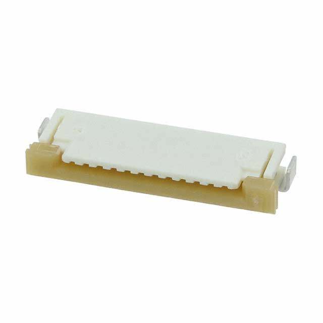
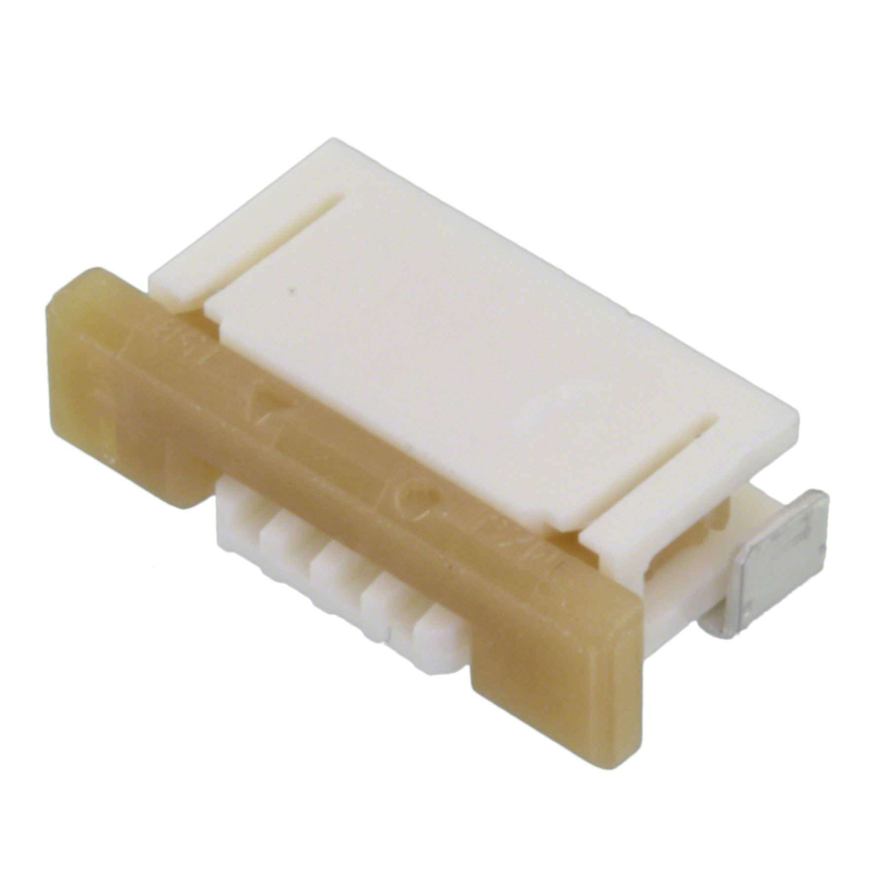
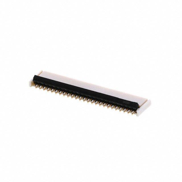
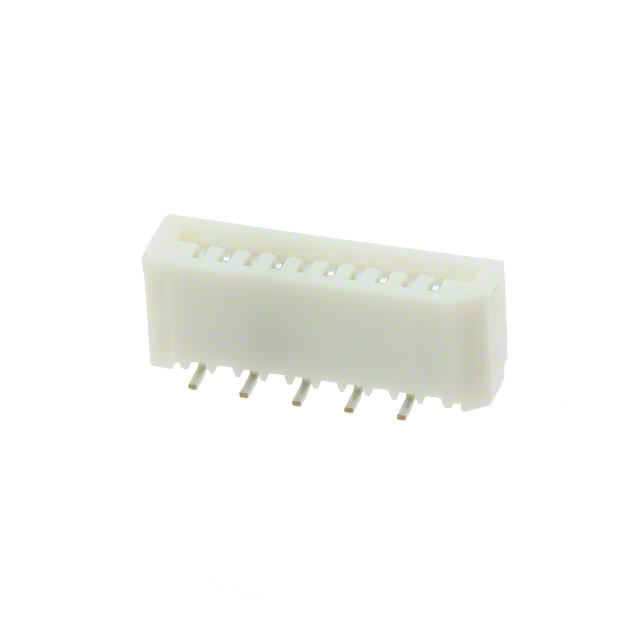
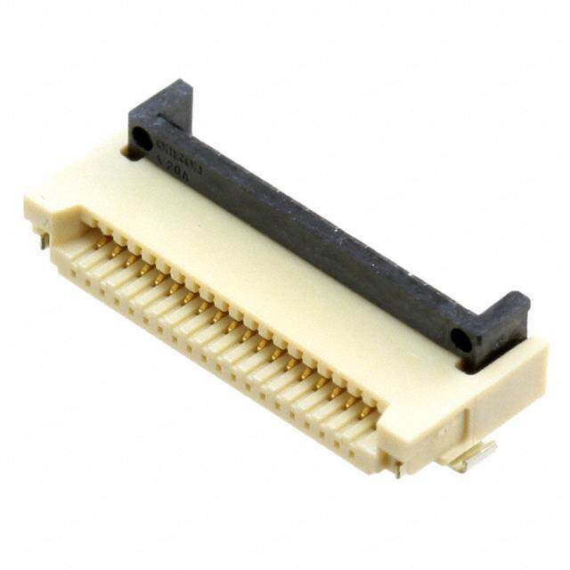
ICGOO电子元器件商城为您提供FH12-45S-0.5SH(55)由Hirose Electric设计生产,在icgoo商城现货销售,并且可以通过原厂、代理商等渠道进行代购。 FH12-45S-0.5SH(55)价格参考。Hirose ElectricFH12-45S-0.5SH(55)封装/规格:FFC,FPC(扁平柔性)连接器, 45 Position FFC, FPC Connector Contacts, Bottom 0.020" (0.50mm) Surface Mount, Right Angle。您可以下载FH12-45S-0.5SH(55)参考资料、Datasheet数据手册功能说明书,资料中有FH12-45S-0.5SH(55) 详细功能的应用电路图电压和使用方法及教程。
| 参数 | 数值 |
| 产品目录 | |
| 描述 | CONN FPC/FFC 45POS .5MM HORZ SMDFFC & FPC连接器 0.5MM 45 POS R/A BTTM SMT GLD |
| 产品分类 | |
| FFC,FCB厚度 | 0.30mm |
| 品牌 | Hirose Electric Co Ltd |
| 产品手册 | |
| 产品图片 |
|
| rohs | 符合RoHS无铅 / 符合限制有害物质指令(RoHS)规范要求 |
| 产品系列 | FFC & FPC连接器,Hirose Connector FH12-45S-0.5SH(55)FH12 |
| 数据手册 | |
| 产品型号 | FH12-45S-0.5SH(55) |
| 产品培训模块 | http://www.digikey.cn/PTM/IndividualPTM.page?site=cn&lang=zhs&ptm=16137 |
| 产品目录绘图 |
|
| 产品目录页面 | |
| 产品种类 | FFC & FPC连接器 |
| 产品类型 | Board Mount |
| 位置数量 | 45 |
| 其它名称 | *FH12-45S-0.5SH(55) |
| 包装 | 剪切带 (CT) |
| 商标 | Hirose Connector |
| 型式 | Female |
| 外壳材料 | 聚酰胺(PA),尼龙 |
| 安装类型 | 表面贴装,直角 |
| 安装角 | Right |
| 安装风格 | SMD/SMT |
| 封装 | Reel |
| 工作温度 | -40°C ~ 85°C |
| 工厂包装数量 | 2000 |
| 扁平柔性类型 | FFC, FPC |
| 材料可燃性等级 | UL94 V-0 |
| 板上高度 | 0.079"(2.00mm) |
| 标准包装 | 1 |
| 特性 | 零插入力(ZIF) |
| 特色产品 | http://www.digikey.cn/product-highlights/zh/fh12-series/52232 |
| 电压额定值 | 50 V |
| 电流额定值 | 500 mA |
| 电缆端类型 | 直形 |
| 端接 | |
| 端接类型 | SMD |
| 系列 | FH12 |
| 联系位置 | Bottom Contact |
| 致动器材料 | 聚苯硫醚(PPS) |
| 节距 | 0.5 mm |
| 触头材料 | 磷青铜 |
| 触头镀层 | 金 |
| 触点材料 | Phosphor Bronze |
| 触点电镀 | Gold |
| 连接器/触头类型 | 触点, 底部 |
| 针脚数 | 45 |
| 锁定功能 | 触发锁 |
| 间距 | 0.020"(0.50mm) |
| 额定电压 | 50V |
| 额定电流 | 0.5A |

.jpg)


(SN).jpg)
.jpg)
.jpg)

- 商务部:美国ITC正式对集成电路等产品启动337调查
- 曝三星4nm工艺存在良率问题 高通将骁龙8 Gen1或转产台积电
- 太阳诱电将投资9.5亿元在常州建新厂生产MLCC 预计2023年完工
- 英特尔发布欧洲新工厂建设计划 深化IDM 2.0 战略
- 台积电先进制程称霸业界 有大客户加持明年业绩稳了
- 达到5530亿美元!SIA预计今年全球半导体销售额将创下新高
- 英特尔拟将自动驾驶子公司Mobileye上市 估值或超500亿美元
- 三星加码芯片和SET,合并消费电子和移动部门,撤换高东真等 CEO
- 三星电子宣布重大人事变动 还合并消费电子和移动部门
- 海关总署:前11个月进口集成电路产品价值2.52万亿元 增长14.8%
.jpg)


PDF Datasheet 数据手册内容提取
0.5mm and 1mm Pitch FPC/FFC Connectors FH12 Series d. e v r e s e R s ht g Ri All D. T L O., ■Features C Rotating one-touch ZIF mechanism C 1. Rotating one-touch ZIF mechanism RI q T The one-touch rotating ZIF mechanism is easier C to operate and works with a light force. E L E 2. Clear tactile click E A clear tactile click is delivered upon the S O successful completion of the mating process R HI 3. Supports high density mounting 8 The FH12’s one-touch ZIF system requires less 1 0 space than a slide locking connector and can be 2 ht mounted in the center of the PCB. g ri 4. Top & Bottom Contact and Vertical y w p Mount type o C There are three connection types available : top 8 contact, bottom contact and a Vertical mount. 1 0 2 5. 1mm pitch product 1. Contact surface of the FPC+FFC c. In addition to the 0.5mm pitch connector, we also e offer a 1mm pitch connector. D 6. Reinforced actuator The FH12S version in 30, 40, 45, 50, and 53 pin counts are offered with a reinforced actuator that provides an extra measure of security against e actuator breakage. 2017.1③ 1
FH12 Series●0.5mm and 1mm Pitch Connectors For FPC/FFC ■Product Specifications Current rating : 0.5A DC(Note 1) Operating Temperature Range : _40 to +85ç (Note 2) Storage Temperature Range : _10 to +50ç (Note 3) Rating Voltage rating : 50V AC Operating Humidity Range : Relative humidity, 90% max. Storage Humidity Range : Relative humidity, 90% max. (Not dewed) (Not dewed) Adaptive FPC/FFC contact specifications t=0.3±0.05 Goldplated Item Specification Conditions 1. Insulation resistance 500Mø minimum 100V DC 2. Withstanding voltage No flashover or insulation breakdown. 150V AC/1 minute 3. Contact resistance 50mø maximum 1mA Contact resistance : 50mø maximum 4. Durability (Insertion/withdrawal) 20 cycles No damage, cracks, or parts dislocation. d. No electrical discontinuity of 1μs or more e Frequency : 10 to 55Hz, single amplitude of 0.75mm, v 5. Vibration Contact resistance : 50mø maximum. ser No damage, cracks, or parts dislocation. for 10 cycles in 3 axial directions e R No electrical discontinuity of 1μs or more s 6. Shock Contact resistance : 50mø maximum. Acceleration of 981m/s2, 6ms duaration, ght No damage, cracks, or parts dislocation. sine half-wave waveform, 3 cycles in each of the 3 axis Ri Contact resistance : 50mø maximum. All 7. Humidity(Steady state) Insulation resistance : 50Mø minimum. 96 hours at 40ç and humidity of 90% to 95% D. No damage, cracks, or parts dislocation. LT Contact resistance : 50mø maximum. Temperature : -40ç/15 to 35ç/85ç/15 to 35ç, O., 8. Temperature Cycle Insulation resistance : 50Mø minimum. Time: 30 /2 to 3 /30 /2 to 3(minutes) No damage, cracks, or parts dislocation. 5 cycles C C No deformation of Reflow : At the recommended temperature profile 9.Resistanceto Soldering heat RI components affecting performance. Manual soldering : 350±10ç for 5 seconds T C Note 1 : When passing the current through all of the contacts,use 70% of the current rating. E Note 2 : Includes temperature rise caused by current flow. L E Note 3 : The term "storage" refers to products stored for long period of time prior to mounting and use. Operating Temperature E Range and Humidity range covers nonconducting condition of installed connectors in storage, shipment or during S O transportation. R HI 8 ■Materials / Finish 1 0 2 ht Part Material Finish Remarks g Polyamide, LCP(60 pos.) Color : Beige yri Insulator UL94V-0 p PPS Color : Dark brown o C Contact Phosphor bronze Gold plated 8 ––––––– 1 Metal Fittings Brass Tinplated 0 2 c.1. ■Product Number Structure e D Refer to the chart below when determining the product specifications from the product number. Please select from the product numbers listed in this catalog when placing orders. FH 12 A - 10 (4) S A - 0.5 SH (****) q w e r t y u i o !0 qSeries Name : FH yContact alignment : Single wSeries No. : 12 uEccentric direction : eBlank : standard type Blank : standard type A : Top contact type A : Eccentric type S : Type with strengthed flip-lock actuator iContacts Pitch : 0.5mm, 1mm rStandard type : Number of contacts oContact type Eccentric type : Number of contacts in 0.5mm housing SH : SMT horizontal mounting type tStandard type : Blank SVA: SMT vertical mounting type Eccentric type : Number of contacts !0Plating specification (54) : Selective gold plated (55) : Gold plated (1)(98) : Gold plated 500 pieces/reel 2
FH12 Series●0.5mm and 1mm Pitch Connectors For FPC/FFC ■Series Configuration Pitch Bottom Contact Type Top Contact Type Vertical mounting Type d. FPC/FFC conductive e v surface(bottom side) r FPC/FFC conductive e s surface e R FH12- ** S-0.5SH P.4 s 0.5mm ht Number of contacts 6, 8, 10, 11, 12, 13, g Ri 14, 15, 16, 17, 18, 19, All 20, 22, 24, 25, 26, 28, D. 30, 32, 33, 34, 35, 36, 40, 45, 50, 53 T L O., C Type with Strengthened Lock Lever C FH12A-** S-0.5SH P.6 FH12-** S-0.5SVA P.7 RI Number of contacts 10, 12 ,15, 16, 18, 20, Number of contacts 6, 10, 12, 13, 15, 16, T C 22, 24, 26, 28, 29, 30, 17, 18, 20, 22, 24, 26, E FH12S- ** S-0.5SH P.5 L 32, 33, 34, 36, 40, 42, 30, 32, 33, 34, 36, 40, E Number of contacts 30, 40, 45, 50, 53 E 45, 50 45, 49, 50, 60 S O R HI 8 1 0 FPC/FFC conductive 2 surface(bottom side) ht g ri y p o C 8 1 0 2 1. c. 1mm e D Standard FH12-**S-1SH P.8 Eccentric FH12-**(**) SA-1SH Standard Number of contacts 5, 6, 7, 8, 9, 11, 12,16,17,22,26 FH12-**S-1SVA P.9 Eccentric Number of contacts 6, 7, 8, 16, 20, 22, Number of contacts 4, 6, 8, 10, 11, 24 14, 19, 24 3
FH12 Series●0.5mm and 1mm Pitch Connectors For FPC/FFC ■0.5mm Pitch Bottom Contact Type A 0.5 (0.2) 8 0. 2 2 1. polarizing mark indicator Number of Contacts indicator B C d. e 85 v 1. r e s 2 e R hts D 5 4.6 g 5.6 Ri All NNoottee 21 :: PThaeck caogpeladn oanri ttya poef eaancdh r eteerlm oinnlayl. lCeahde cwki tphainc ksapgeicnigfi esdp edcimifiecnastiioonn. is 0.1mm Max. D. Note 3 : Slight variations in color of the plastic compounds do not affect form, fit or function of the connector. T Note 4 : After reflow, the terminal plating may change color, however this does not represent a quality issue. O., L Note 5 : Ilof cthke arect uisa tnoor (pFrHob1l2eSm- *wSi-t0h. 5thSeH c).o Snntaencdtoarr dh etyigphet ,c ownen erecctoorm hmeiegnhdt :t h2em tmyp Ce owninthe cthtoer shtereignhgt tohfe ntyepde Fwliipth- C strengthened Flip-lock actuator : 2.4mm C Unit : mm RI T Part No. HRS No. No. of Contacts A B C D C E FH12-6S-0.5SH(**) 586-0582-5 ** 6 2.5 06.1 7.1 3.57 L E FH12-8S-0.5SH(**) 586-0744-5 ** 8 3.5 07.1 8.1 4.57 E S FH12-10S-0.5SH(**) 586-0522-3 ** 10 4.5 08.1 9.1 5.57 O R FH12-11S-0.5SH(**) 586-0600-5 ** 11 5.0 08.6 9.6 6.07 HI FH12-12S-0.5SH(**) 586-0704-0 ** 12 5.5 09.1 10.1 6.57 8 1 FH12-13S-0.5SH(**) 586-0549-0 ** 13 6.0 09.6 10.6 7.07 0 2 ht FH12-14S-0.5SH(**) 586-0533-0 ** 14 6.5 10.1 11.1 7.57 g FH12-15S-0.5SH(**) 586-0523-6 ** 15 7.0 10.6 11.6 8.07 ri y p FH12-16S-0.5SH(**) 586-0531-4 ** 16 7.5 11.1 12.1 8.57 o C FH12-17S-0.5SH(**) 586-0606-1 ** 17 8.0 11.6 12.6 9.07 8 1 FH12-18S-0.5SH(**) 586-0530-1 ** 18 8.5 12.1 13.1 9.57 0 2 FH12-19S-0.5SH(**) 586-0534-2 ** 19 9.0 12.6 13.6 10.07 1. c. FH12-20S-0.5SH(**) 586-0524-9 ** 20 9.5 13.1 14.1 10.57 e D FH12-22S-0.5SH(**) 586-0532-7 ** 22 10.5 14.1 15.1 11.57 FH12-24S-0.5SH(**) 586-0521-0 ** 24 11.5 15.1 16.1 12.57 FH12-25S-0.5SH(**) 586-0692-3 ** 25 12.0 15.6 16.6 13.07 FH12-26S-0.5SH(**) 586-0576-2 ** 26 12.5 16.1 17.1 13.57 FH12-28S-0.5SH(**) 586-0612-4 ** 28 13.5 17.1 18.1 14.57 Note 5 FH12-30S-0.5SH(**) 586-0525-1 ** 30 14.5 18.1 19.1 15.57 FH12-32S-0.5SH(**) 586-0681-7 ** 32 15.5 19.1 20.1 16.57 FH12-33S-0.5SH(**) 586-0520-8 ** 33 16.0 19.6 20.6 17.07 FH12-34S-0.5SH(**) 586-0617-8 ** 34 16.5 20.1 21.1 17.57 FH12-35S-0.5SH(**) 586-0740-4 ** 35 17.0 20.6 21.6 18.07 FH12-36S-0.5SH(**) 586-0526-4 ** 36 17.5 21.1 22.1 18.57 Note 5 FH12-40S-0.5SH(**) 586-0527-7 ** 40 19.5 23.1 24.1 20.57 Note 5 FH12-45S-0.5SH(**) 586-0528-0 ** 45 22.0 25.6 26.6 23.07 Note 5 FH12-50S-0.5SH(**) 586-0529-2 ** 50 24.5 28.1 29.1 25.57 Note 5 FH12-53S-0.5SH(**) 586-0595-7 ** 53 26.0 29.6 30.6 27.07 Note 1 : Embossed tape reel packaging (2,000 pcs/reel, 500 pcs/reel). Order by number of reels. 4
FH12 Series●0.5mm and 1mm Pitch Connectors For FPC/FFC ■0.5mm Pitch Bottom Contact Type with Strengthened Flip-lock Actuator A 0.5 (0.2) 8 0. 2 2 1. polarizing mark indicator Number of Contacts indicator B C d. e 25 rv 2. e s 4 e 2. 2 R s ht D 4.6 g 5.6 Ri All D. NNoottee 12 :: TPhaec kcaogpeladn oanri ttya poef eaancdh r eteerlm oinnlayl. lCeahde cwki tphainc ksapgeicnigfi esdp edcimifiecnastiioonn. is 0.1mm Max. T L Note 3 : Slight variations in color of the plastic compounds do not affect form, fit or function of the connector. O., Note 4 : After reflow, the terminal plating may change color, however this does not represent a quality issue. C C RI T C E Unit : mm L E Part No. HRS No. No. of Contacts A B C D E S FH12S-30S-0.5SH(**) 586-0667-6 ** 30 14.5 18.1 19.1 15.57 O R FH12S-40S-0.5SH(**) 586-0640-0 ** 40 19.5 23.1 24.1 20.57 HI 8 FH12S-45S-0.5SH(**) 586-0665-0 ** 45 22.0 25.6 26.6 23.07 1 0 FH12S-50S-0.5SH(**) 586-0642-5 ** 50 24.5 28.1 29.1 25.57 2 ht FH12S-53S-0.5SH(**) 586-0691-0 ** 53 26.0 29.6 30.6 27.07 g ri Note 1 : Embossed tape reel packaging (2,000 pcs/reel, 500 pcs/reel). y p Order by number of reels. o C 8 1 0 2 1. c. e D 5
FH12 Series●0.5mm and 1mm Pitch Connectors For FPC/FFC ■0.5mm Pitch Top Contact Type A B C 0.5 ( 0.2 ) )5 8 ( 1. 6.2 polarizing mark indicator D ) 6 3.( 2 d. E ( 0.45 ) ve 1.45 0.8 r e es 85 R 0. s ht 2 g 2. Ri All D. T Note 1 : The coplanarity of each terminal lead within specified dimension is 0.1mm Max. L Note 2 : Packaged on tape and reel only. Check packaging specification. O., Note 3 : Slight variations in color of the plastic compounds do not affect form, fit or function of the connector. C Note 4 : After reflow, the terminal plating may change color, however this does not represent a quality issue. C Unit : mm RI T Part No. HRS No. No. of Contacts A B C D E C E FH12A-10S-0.5SH(**) 586-0550-9 ** 10 9.1 8.35 4.5 9.5 5.57 L E FH12A-12S-0.5SH(**) 586-0696-4 ** 12 10.1 9.35 5.5 10.5 6.57 E S FH12A-15S-0.5SH(**) 586-0551-1 ** 15 11.6 10.85 7.0 12.0 8.07 O R FH12A-16S-0.5SH(**) 586-0552-4** 16 12.1 11.35 7.5 12.5 8.57 HI 8 FH12A-18S-0.5SH(**) 586-0553-7 ** 18 13.1 12.35 8.5 13.5 9.57 1 0 FH12A-20S-0.5SH(**) 586-0554-0 ** 20 14.1 13.35 9.5 14.5 10.57 2 ht FH12A-22S-0.5SH(**) 586-0686-0 ** 22 15.1 14.35 10.5 15.5 11.57 g ri FH12A-24S-0.5SH(**) 586-0555-2** 24 16.1 15.35 11.5 16.5 12.57 y op FH12A-26S-0.5SH(**) 586-0663-5** 26 17.1 16.35 12.5 17.5 13.57 C 8 FH12A-28S-0.5SH(**) 586-0725-0** 28 18.1 17.35 13.5 18.5 14.57 1 FH12A-29S-0.5SH(**) 586-0585-3** 29 18.6 17.85 14.0 19.0 15.07 0 2 1. FH12A-30S-0.5SH(**) 586-0556-5** 30 19.1 18.35 14.5 19.5 15.57 ec. FH12A-32S-0.5SH(**) 586-0687-3** 32 20.1 19.35 15.5 20.5 16.57 D FH12A-33S-0.5SH(**) 586-0570-6** 33 20.6 19.85 16.0 21.0 17.07 FH12A-34S-0.5SH(**) 586-0670-0** 34 21.1 20.35 16.5 21.5 17.57 FH12A-36S-0.5SH(**) 586-0662-2** 36 22.1 21.35 17.5 22.5 18.57 FH12A-40S-0.5SH(**) 586-0557-8** 40 24.1 23.35 19.5 24.5 20.57 FH12A-42S-0.5SH(**) 586-0698-0 ** 42 25.1 24.35 20.5 25.5 21.57 FH12A-45S-0.5SH(**) 586-0558-0 ** 45 26.6 25.85 22.0 27.0 23.07 FH12A-50S-0.5SH(**) 586-0559-3 ** 50 29.1 28.35 24.5 29.5 25.57 Note 1 : Embossed tape reel packaging (2,000 pcs/reel). Order by number of reels. 6
FH12 Series●0.5mm and 1mm Pitch Connectors For FPC/FFC ■0.5mm Pitch Vertical mounting Type Mated Cross-sectional Diagram (0.2) 1 ( 0.15 ) FPC/FFC Contact Surface ()1.4()2.15 1 F 0.5 2.5 0.5 A (4.25) B (1.75) ved. ()4.85 3.65.5 r e s e 0.5 R C s D ht E g Ri All D. T L Note 1 : The coplanarity of each terminal lead within specified dimension is 0.1mm Max. O., Note 2 : Packaged on tape and reel only. Check packaging specification. Note 3 : Slight variations in color of the plastic compounds do not affect form, fit or function of the connector. C C Note 4 : After reflow, the terminal plating may change color, however this does not represent a quality issue. RI T C E L Unit : mm E E Part No. HRS No. No. of Contacts A B C D E F S O FH12-6S-0.5SVA(54) 586-0756-4 54 6 6.4 4.9 2.5 4.5 6.2 4 R HI FH12-10S-0.5SVA(54) 586-0806-0 54 10 8.4 6.9 4.5 6.5 8.2 4 8 FH12-12S-0.5SVA(54) 586-0757-7 54 12 9.4 7.9 5.5 7.5 9.2 4 1 0 2 FH12-13S-0.5SVA(54) 586-0807-3 54 13 9.9 8.4 6.0 8.0 9.7 4 ght FH12-15S-0.5SVA(54) 586-0808-6 54 15 10.9 9.4 7.0 9.0 10.7 4 yri FH12-16S-0.5SVA(54) 586-0809-9 54 16 11.4 9.9 7.5 9.5 11.2 4 p Co FH12-17S-0.5SVA(54) 586-0810-8 54 17 11.9 10.4 8.0 10.0 11.7 4 8 FH12-18S-0.5SVA(54) 586-0811-0 54 18 12.4 10.9 8.5 10.5 12.2 4 1 20 FH12-20S-0.5SVA(54) 586-0812-3 54 20 13.4 11.9 9.5 11.5 13.2 4 c.1. FH12-22S-0.5SVA(54) 586-0813-6 54 22 14.4 12.9 10.5 12.5 14.2 8 De FH12-24S-0.5SVA(54) 586-0814-9 54 24 15.4 13.9 11.5 13.5 15.2 8 FH12-26S-0.5SVA(54) 586-0815-1 54 26 16.4 14.9 12.5 14.5 16.2 8 FH12-30S-0.5SVA(54) 586-0750-8 54 30 18.4 16.9 14.5 16.5 18.2 8 FH12-32S-0.5SVA(54) 586-0816-4 54 32 19.4 17.9 15.5 17.5 19.2 8 FH12-33S-0.5SVA(54) 586-0818-0 54 33 19.9 18.4 16.0 18.0 19.7 8 FH12-34S-0.5SVA(54) 586-0817-7 54 34 20.4 18.9 16.5 18.5 20.2 8 FH12-36S-0.5SVA(54) 586-0819-2 54 36 21.4 19.9 17.5 19.5 21.2 8 FH12-40S-0.5SVA(54) 586-0804-5 54 40 23.4 21.9 19.5 21.5 23.2 8 FH12-45S-0.5SVA(54) 586-0820-1 54 45 25.9 24.4 22.0 24.0 25.7 8 FH12-49S-0.5SVA(54) 586-0821-4 54 49 27.9 26.4 24.0 26.0 27.7 8 FH12-50S-0.5SVA(54) 586-0805-8 54 50 28.4 26.9 24.5 26.5 28.2 8 FH12-60S-0.5SVA(54) 586-0749-9 54 60 33.4 31.9 29.5 31.5 33.2 8 Note 1 : Embossed tape reel packaging (1,000 pcs/reel, 500 pcs/reel). Order by number of reels. 7
FH12 Series●0.5mm and 1mm Pitch Connectors For FPC/FFC ■1mm Pitch Type Bottom Contact Type 2.3 A E 1.0 (0.2) 8 Mated Cross-sectional Diagram 0. 2 1.2 FPC/FFC Contact Surface (2.1) (3.1) (1.3) polarizing mark indicator Number of Contacts indicator B C ved. (4.8) 1.85 er 2 s e R D 4.6 s 5.6 ht g Ri All D. NNoottee 12 :: TPhaec kcaogpeladn oanri ttya poef eaancdh r eteerlm oinnlayl. lCeahde cwki tphainc ksapgeicnigfi esdp edcimifiecnastiioonn. is 0.1mm Max. T L Note 3 : Slight variations in color of the plastic compounds do not affect form, fit or function of the connector. O., Note 4 : After reflow, the terminal plating may change color, however this does not represent a quality issue. C C RI Unit : mm T C E Part No. HRS No. No. of Contacts A B C D E L E FH12-5S-1SH(**) 586-0591-6 ** 5 4 8.6 9.6 6.07 2.3 E S FH12-6S-1SH(**) 586-0607-4 ** 6 5 9.6 10.6 7.07 2.3 O R FH12-7S-1SH(**) 586-0535-5 ** 7 6 10.6 11.6 8.07 2.3 HI FH12-8S-1SH(**) 586-0579-0 ** 8 7 11.6 12.6 9.07 2.3 8 e 01 typ FH12-9S-1SH(**) 586-0540-5 ** 9 8 12.6 13.6 10.07 2.3 2 d ht dar FH12-11S-1SH(**) 586-0668-9 ** 11 10 14.6 15.6 12.07 2.3 yrig Stan FH12-12S-1SH(**) 586-0741-7 ** 12 11 15.6 16.6 13.07 2.3 p FH12-16S-1SH(**) 586-0536-8 ** 16 15 19.6 20.6 17.07 2.3 o C FH12-17S-1SH(**) 586-0739-5 ** 17 16 20.6 21.6 18.07 2.3 8 1 FH12-22S-1SH(**) 586-0547-4 ** 22 21 25.6 26.6 23.07 2.3 0 2 FH12-26S-1SH(**) 586-0592-9** 26 25 29.6 30.6 27.07 2.3 1. c. FH12-10(4)SA-1SH(**) 586-0537-0 ** 4 3 8.1 9.1 5.57 2.8 e D FH12-14(6)SA-1SH(**) 586-0538-3 ** 6 5 10.1 11.1 7.57 2.8 e FH12-18(8)SA-1SH(**) 586-0539-6** 8 7 12.1 13.1 9.57 2.8 p y ct FH12-22(10)SA-1SH(**) 586-0541-8** 10 9 14.1 15.1 11.57 2.8 ntri FH12-24(11)SA-1SH(**) 586-0542-0 ** 11 10 15.1 16.1 12.57 2.8 e c Ec FH12-30(14)SA-1SH(**) 586-0543-3 ** 14 13 18.1 19.1 15.57 2.8 FH12-40(19)SA-1SH(**) 586-0546-1 ** 19 18 23.1 24.1 20.57 2.8 FH12-50(24)SA-1SH(**) 586-0548-7** 24 23 28.1 29.1 25.57 2.8 Note 1 : Embossed tape reel packaging (2,000 pcs/reel, 500 pcs/reel). Order by number of reels. 8
FH12 Series●0.5mm and 1mm Pitch Connectors For FPC/FFC ■1mm Pitch Vertical Mounting Type Mated Cross-sectional Diagram (0.2) 2 (0.15) FPC/FFC Contact Surface 4)5) (1.2.1 ( 2 F 0.5 2.5 0.5 A (4.25) B (1.75) d. erve (4.85) 3.65.5 s e R 1.0 s C 3.8(Metal fitting dimension) ht D Rig E All D. Note 1 : The coplanarity of each terminal lead within specified dimension is 0.1mm Max. T L Note 2 : Packaged on tape and reel only. Check packaging specification. O., NNoottee 34 :: SAlfitgehr tr evafloriwat,i othnes tine rcmoilnoar lo pfl athtien gp lmasatyic cchoamnpgoeu cnodlosr d, oh onwoet vaeffre tchti sfo drmoe, sfi tn oort fruenpcretisoenn ot fa t hqeu acloitnyn iesscutoer.. C C RI T C E Unit : mm L E E Part No. HRS No. No. of Contacts A B C D E F S O FH12-06S-1SVA(54) 586-0822-0 54 6 9.9 8.4 5 8 9.7 4 R HI FH12-07S-1SVA(54) 586-0823-0 54 7 10.9 9.4 6 9 10.7 4 8 FH12-08S-1SVA(54) 586-0824-0 54 8 11.9 10.4 7 10 11.7 4 1 0 FH12-16S-1SVA(54) 586-0825-0 54 16 19.9 18.4 15 18 19.7 8 2 ht FH12-20S-1SVA(54) 586-0826-0 54 20 23.9 22.4 19 22 23.7 8 g yri FH12-22S-1SVA(54) 586-0827-0 54 22 25.9 24.4 21 24 25.7 8 p o FH12-24S-1SVA(54) 586-0828-0 54 24 27.9 26.4 23 26 27.7 8 C 8 Note1 : Embossed tape reel packaging (1,000 pcs/reel, 500 pcs/reel). 1 0 Order by number of reels. 2 1. c. e D 9
FH12 Series●0.5mm and 1mm Pitch Connectors For FPC/FFC BRecommended FPC/FFC dimensions and Land/Metal Mask dimensions ●0.5mm Pitch Product FPC/FFC dimensions Land /Metal Mask dimensions B±0.1 0.1± C±0.1 MIN MIN 2.2 3.5 4.5 0.1± 0.5±0.05 0.35±0.03(FPC) 0.3±0.05 1.5 0.3±0.03(FFC) 0.5±0.1 A±0.05 0.3±0.03(Land) 0.5mm B±0.07 0.5±0.1 0.1± 0.5±0.05 0.25±0.03(Metal mask) d. Pitch *Set the stiffener thickness to 0.188 (7.5mil) min. 1.3 A±0.05 e Bottom v Unit : mm Recommended metal mask thickness : 0.15mm Unit : mm er Contact s Dimension Dimension Dimension Dimension e Type Number A B Number A B Number A B C Number A B C R of Contacts of Contacts of Contacts of Contacts s 6 2.5 3.5 25 12.0 13.0 6 2.5 8.1 4.5 25 12.0 17.6 14.0 ht g 8 3.5 4.5 26 12.5 13.5 8 3.5 9.1 5.5 26 12.5 18.1 14.5 Ri 10 4.5 5.5 28 13.5 14.5 10 4.5 10.1 6.5 28 13.5 19.1 15.5 All 11 5.0 6.0 29 14.0 15.0 11 5.0 10.6 7.0 29 14.0 19.6 16.0 D. 0.5mm 12 5.5 6.5 30 14.5 15.5 12 5.5 11.1 7.5 30 14.5 20.1 16.5 LT Pitch 13 6.0 7.0 32 15.5 16.5 13 6.0 11.6 8.0 32 15.5 21.1 17.5 O., Top 14 6.5 7.5 33 16.0 17.0 14 6.5 12.1 8.5 33 16.0 21.6 18.0 C Contact 15 7.0 8.0 34 16.5 17.5 15 7.0 12.6 9.0 34 16.5 22.1 18.5 C Type 16 7.5 8.5 35 17.0 18.0 16 7.5 13.1 9.5 35 17.0 22.6 19.0 RI 17 8.0 9.0 36 17.5 18.5 17 8.0 13.6 10.0 36 17.5 23.1 19.5 T C 18 8.5 9.5 40 19.5 20.5 18 8.5 14.1 10.5 40 19.5 25.1 21.5 E 19 9.0 10.0 42 20.5 21.5 19 9.0 14.6 11.0 42 20.5 26.1 22.5 L E 20 9.5 10.5 45 22.0 23.0 20 9.5 15.1 11.5 45 22.0 27.6 24.0 E S 22 10.5 11.5 50 24.5 25.5 22 10.5 16.1 12.5 50 24.5 30.1 26.5 O 24 11.5 12.5 53 26.0 27.0 24 11.5 17.1 13.5 53 26.0 31.6 28.0 R HI 8 1 Even contact number Odd contact number 0 2 No.1 contact No.1 contact Copyright 2MIN 3MIN 1.80.1±0.11.8± 00..685±±00A.0.15±((M0L.ea1tnald m)ask) 1.50.1±0.11.5±4.50.1± 1.80.1±1.80.1± 00..685±±00.A.015±((ML0ae.nt1adl m)ask) 1.50.1±1.50.1±4.50.1± 018 0.5±0.1 0.AB5±±±000...000557 00..3305±.±50±0.0.003.3(1F(FFPCC)) 0.3±0.05 0.511±±±000...000555 B±0.05 001..5±6±±00.0.005.1(5M(Leatanl dm)ask0).511±±±000...000555 B±0.05 001..±56±±000..00.515((MLeatnald m)ask) 2 1. *Set the stiffener thickness to 0.188 (7.5mil) min. Recommended metal mask thickness : 0.15mm c. 0.5mm Unit : mm Unit : mm e D Pitch Dimension Dimension Dimension Dimension Vertical Number A B Number A B Number A B Number A B of Contacts of Contacts of Contacts of Contacts Mountin 6 02.5 03.5 26 12.5 13.5 10 06.5 04.5 26 14.5 12.5 g Type 10 04.5 05.5 30 14.5 15.5 12 07.5 05.5 30 16.5 14.5 12 05.5 06.5 32 15.5 16.5 13 08.0 06.0 32 17.5 15.5 13 06.0 07.0 33 16.0 17.0 15 09.0 07.0 33 18.0 16.0 15 07.0 08.0 34 16.5 17.5 16 09.5 07.5 34 18.5 16.5 16 07.5 08.5 36 17.5 18.5 17 10.0 08.0 36 19.5 17.5 17 08.0 09.0 40 19.5 20.5 18 10.5 08.5 40 21.5 19.5 18 08.5 09.5 45 22.0 23.0 20 11.5 09.5 45 24.0 22.0 20 09.5 10.5 49 24.0 25.0 22 12.5 10.5 49 26.0 24.0 22 10.5 11.5 50 24.5 25.5 24 13.5 11.5 50 26.5 24.5 24 11.5 12.5 60 29.5 30.5 60 31.5 29.5 10
FH12 Series●0.5mm and 1mm Pitch Connectors For FPC/FFC BRecommended FPC/FFC dimensions and Land/Metal Mask dimensions ●1mm Pitch Product FPC/FFC dimensions Land /Metal Mask dimensions d. e v r e s Re 1mm πSet the stiffener thickness to 0.188 (7.5mil) min. Recommended metal mask thickness : 0.15mm s ht Pitch g Bottom Unit : mm Unit : mm Ri All CToynptaect NumbDeimrension A B C NumbDeimrension A B C NumbeDrimension A B C D NumbeDrimension A B C D D. of Con5tacts 04 06 1 of Con4tacts 03 05.5 1.5 of Cont5acts 04 10.6 07 1.5 of Cont4acts 03 10.106.5 2 T L 6 05 07 1 6 05 07.5 1.5 6 05 11.6 08 1.5 6 05 12.108.5 2 O., 7 06 08 1 ype 8 07 09.5 1.5 7 06 12.6 09 1.5 ype 8 07 14.110.5 2 T T C pe 8 07 09 1 c 10 09 11.5 1.5 pe 8 07 13.6 10 1.5 c 10 09 16.112.5 2 RIC dTy 9 08 10 1 entri 11 10 12.5 1.5 dTy 9 08 14.6 11 1.5 entri 11 10 17.113.5 2 T ar 11 10 12 1 cc 14 13 15.5 1.5 ar 11 10 16.6 13 1.5 cc 14 13 20.116.5 2 C nd 12 11 13 1 E 19 18 20.5 1.5 nd 12 11 17.6 14 1.5 E 19 18 25.121.5 2 E a a L St 16 15 17 1 24 23 25.5 1.5 St 16 15 21.6 18 1.5 24 23 30.126.5 2 E E 17 16 18 1 17 16 22.6 19 1.5 S 22 21 23 1 22 21 27.6 24 1.5 O 26 25 27 1 26 25 31.6 28 1.5 R HI 8 1 0 2 ht g ri y p o C 8 1 0 2 1. c. e D 1mm Pitch Vertical Mounting *Set the stiffener thickness to 0.188 (7.5mil) min. Recommended metal mask thickness : 0.15mm Type Unit : mm Unit : mm Dimension Dimension Number A B Number A B of Contacts of Contacts 6 05 07 6 08 05 7 06 08 7 09 06 8 07 09 8 10 07 16 15 17 16 18 15 20 19 21 20 22 19 22 21 23 22 24 21 24 23 25 24 26 23 11
FH12 Series●0.5mm and 1mm Pitch Connectors For FPC/FFC BPackaging Specification Embossed Carrier Tape Dimensions Horizontal Type (Common to Bottom/Top Contact, 0.5mm/1mm Pitch) d. e rv (2.0) Flat surface for placement se with Automatic equipment e R s ht g Reel Dimensions (Common to All Types) Ri All (ø13) (D : INSIDE) D. End portion Mounting portion Lead portion (400mm min.) T L CO., ( )( ) C RI ( E : OUTSIDE) Blank portion Embossed carrier tape Blank portion Top cover tape T (10 pockets min.) (10 pockets min.) C E ●0.5mm Pitch Bottom/Top Contact Type L Unit : mm E Dimension Dimension E Number A B C D E Number A B C D E S of Contacts of Contacts O 6 16 ---------- 07.5 17.4 21.4 25 24 ---------- 11.5 25.4 29.4 R HI 8 16 ---------- 07.5 17.4 21.4 26 24 ---------- 11.5 25.4 29.4 8 10 16 ---------- 07.5 17.4 21.4 28 32 28.4 14.2 33.4 37.4 1 11 16 ---------- 07.5 17.4 21.4 29 32 28.4 14.2 33.4 37.4 0 ght 2 1123 2244 -------------------- 1111..55 2255..44 2299..44 3302 3322 2288..44 1144..22 3333..44 3377..44 yri 14 24 ---------- 11.5 25.4 29.4 33 32 28.4 14.2 33.4 37.4 p o 15 24 ---------- 11.5 25.4 29.4 34 32 28.4 14.2 33.4 37.4 C 16 24 ---------- 11.5 25.4 29.4 35 44 40.4 20.2 45.4 49.4 18 17 24 ---------- 11.5 25.4 29.4 36 44 40.4 20.2 45.4 49.4 20 18 24 ---------- 11.5 25.4 29.4 40 44 40.4 20.2 45.4 49.4 1. 19 24 ---------- 11.5 25.4 29.4 42 44 40.4 20.2 45.4 49.4 c. e 20 24 ---------- 11.5 25.4 29.4 45 44 40.4 20.2 45.4 49.4 D 22 24 ---------- 11.5 25.4 29.4 50 44 40.4 20.2 45.4 49.4 24 24 ---------- 11.5 25.4 29.4 53 44 40.4 20.2 45.4 49.4 ●1mm Pitch Bottom Contact Type Unit : mm Dimension Dimension Number A B C D E Number A B C D E of Contacts of Contacts 5 16 ---------- 07.5 17.4 21.4 4 16 ---------- 07.5 17.4 21.4 6 24 ---------- 11.5 25.4 29.4 6 24 ---------- 11.5 25.4 29.4 e 7 24 ---------- 11.5 25.4 29.4 yp 8 24 ---------- 11.5 25.4 29.4 T pe 8 24 ---------- 11.5 25.4 29.4 c 10 24 ---------- 11.5 25.4 29.4 Ty 9 24 ---------- 11.5 25.4 29.4 ntri 11 24 ---------- 11.5 25.4 29.4 d e ar 11 24 ---------- 11.5 25.4 29.4 cc 14 32 28.4 14.2 33.4 37.4 nd 12 24 ---------- 11.5 25.4 29.4 E 19 44 40.4 20.2 45.4 49.4 a St 16 32 28.4 14.2 33.4 37.4 24 44 40.4 20.2 45.4 49.4 17 44 40.4 20.2 45.4 49.4 22 44 40.4 20.2 45.4 49.4 26 44 40.4 20.2 45.4 49.4 12
FH12 Series●0.5mm and 1mm Pitch Connectors For FPC/FFC Vertical Mounting Type (Common to 0.5mm/1mm Pitch) d. e v r e s e R s Flat surface for placement ht (1.75) with Automatic equipment g Ri All D. T L Reel Dimensions (Common to All Types) O., 3) C (ø1 (D : INSIDE) C End portion Mounting portion Lead portion (400mm min.) RI T C ELE ( )( ) E Blank portion Embossed carrier tape Blank portion Top cover tape S ( E : OUTSIDE) O (10 pockets min.) (10 pockets min.) R HI 8 01 ●0.5mm Pitch Vertical mounting Type Unit : mm 2 ght NumberDimension A B C D E NumberDimension A B C D E ri of Contacts of Contacts y p 6 16 ---------- 07.5 17.4 21.4 26 24 ---------- 11.5 25.4 29.4 o C 8 10 16 ---------- 07.5 17.4 21.4 30 32 28.4 14.2 33.4 37.4 1 12 16 ---------- 07.5 17.4 21.4 32 32 28.4 14.2 33.4 37.4 0 2 1. 13 24 ---------- 11.5 25.4 29.4 33 32 28.4 14.2 33.4 37.4 c. 15 24 ---------- 11.5 25.4 29.4 34 44 40.4 20.2 45.4 49.4 e D 16 24 ---------- 11.5 25.4 29.4 36 44 40.4 20.2 45.4 49.4 17 24 ---------- 11.5 25.4 29.4 40 44 40.4 20.2 45.4 49.4 18 24 ---------- 11.5 25.4 29.4 45 44 40.4 20.2 45.4 49.4 20 24 ---------- 11.5 25.4 29.4 49 44 40.4 20.2 45.4 49.4 22 24 ---------- 11.5 25.4 29.4 50 44 40.4 20.2 45.4 49.4 24 24 ---------- 11.5 25.4 29.4 60 56 52.4 26.2 57.4 61.4 ●1mm Pitch Vertical mounting Type Unit : mm Dimension Number A B C D E of Contacts 6 24 ---------- 11.5 25.4 29.4 7 24 ---------- 11.5 25.4 29.4 8 24 ---------- 11.5 25.4 29.4 16 32 28.4 14.2 33.4 37.4 20 44 40.4 20.2 45.4 49.4 22 44 40.4 20.2 45.4 49.4 24 44 40.4 20.2 45.4 49.4 13
FH12 Series●0.5mm and 1mm Pitch Connectors For FPC/FFC BFH12 Series FPC/FFC Construction (Recommended Specifications) 1. FFC FFC : Flexible Flat Cable Material Name Material Thickness (μm) Polyester film (12) Adhesive Thermoplastic polyester (30) (Nickel under plated / Gold plated), 35 soft copper film Adhesive Polyester type 30 Polyester 12 Adhesive Polyester type 30 Stiffener Polyester type 188 (Note) d. e Total 295 v r e s *Real tolerance of thickness dimension is on the order of ±20μm (275 to 315μm) e R Note :Use of a thicker FFC results in a stiffer lock action and the lock is more easily released. hts A factor that contributes to thicker FFC is the use of 250μm stiffener which is thicker than the standard (188μm) g product. This results in a total thickness of 357μm. Ri When using FFC, control of FFC thickness becomes easy if you indicate to us the thickness of the stiffener. All D. 2. FPC FPC : Flexible Printed Circuit T L O., Material Name Material Thickness (μm) C Covering layer film Polyimide 1 mil (25) C RI Cover adhesive (25) T C Nickel under plated 1to 5μm / E Surface treatmenta 3 L Gold plated 0.2μm E E Copper foil Cu 1oz 35 S O Base adhesive Heat-hardened adhesive 25 R HI Base film Polyimide 1 mil 25 8 1 Reinforcement material adhesive Heat-hardened adhesive 30 0 2 Stiffener Polyimide 7 mil 175 ht g Total 293 ri y p 3. Precautions o C 8 1. This specification is a recommendation for the construction of the FH12 Series FPC and FFC (t=0.3±0.05). 1 0 2. For details about the construction, please contact the FPC/FFC manufacturers. 2 1. ec. ■Recommended Temperature Profile D MAX 250ç HRS test conditions Solder method :Reflow, IR/hot air 250 Environment : Room air 230ç Solder composition :Paste, 96.5%Sn/3%Ag/0.5%Cu (Senju Metal Industry, Co., Ltd.’s ure 200 200ç Part Number: M705-221CM5-32- at 10.5) er mp Test board :Glass epoxy 40mm∞80mm∞1.6mm thick Te 150 Land dimensions :Top and bottom 150ç contact type 0.3mm∞1.3mm (ç) Vertical mounting type 100 0.6mm∞1.5mm Metal mask :Top and bottom contact type 0.25mm∞1.3mm∞0.15mm thick 50 Vertical mounting type 0.5mm∞1.5mm∞0.15mm thick 25ç (60 seconds) 90 to 120 seconds 30 seconds Preheating Soldering This temperature profile is based on the above conditions. 0 In individual applications the actual temperature may vary, Start depending on solder paste type, volume/thickness and Time board size/thickness. Consult your solder paste and equipment manufacturer for specific recommendations. 14
FH12 Series●0.5mm and 1mm Pitch Connectors For FPC/FFC BConnector Operating Instructions, precautions and recommendations ●Bottom Contact Type (common for 0.5mm/1mm Pitch) Operation Precautions 1. FPC/FFC Termination procedure. 1) Avoid grasping the actuator with two fingers or Connector installed on the board. lifting the actuator with fingernail. 1) Lift up the actuator. Use thumb or index finger. d. e v r e 2) Do not use a thin tool such as the tip of a s e screwdriver to release the lock lever. Doing so R s will cause deformation of the contacts. ht g Ri All D. T L O., C C 3)Do not apply force in the direction of arrows A, B, or C RI while the lock lever is open. T Doing so will cause the lock lever to become disen gaged, C E or will damage the hook portion of the connector body. L E E S O R HI 2) Fully insert the FPC/FFC parallel to mounting 8 surface, with the exposed conductive traces 1 0 facing down. 2 ht g 4) When inserting the FPC/FFC, do not forcefully rub against yri the surface beneath the connector insertion slot. p o Doing so will result in the FPC/FFC forcefully striking the C 18 coof nthtaec FtsP aCn/FdF thCi sc ownildl cuacutosres ,c aonndta octth deer fiorrremgautliaornit,i epse.eling 0 2 1. c. e D FPC/FFC conductive traces 5) Insert the FPC/FFC at the proper position of the connector insertion slot, and insert perpendicularly with respect to the con- nector. Improper insertion will cause continuity problems, disen- gagement of the lock lever, and damage to the hook portion. 15
FH12 Series●0.5mm and 1mm Pitch Connectors For FPC/FFC ●Bottom Contact Type (common for 0.5mm/1mm Pitch) Operation Precautions 3) Rotate down the actuator until firmly closed. 6) Partial insertion of the FPC/FFC, offset insertion, It is critical that the inserted FPC/FFC is not and diagonal insertion will result in an unfavor- moved and remains fully inserted. Should the able engagement of the lock lever in which the FPC/FFC be moved, open the actuator and lock lever is raised. To correct this, first remove repeat the process, starting with Step 1. the FPC/FFC and then reinsert it. Forcing the lock will damage the connector. d. e v r e s e R Stiffener s ht g Ri All D. T 7) When locking, handle the FPC/FFC so that a L O., load is not applied to the FPC/FFC as would C occur by pulling the FPC/FFC, or lifting it, etc. C When a load is applied in the opposite direc- RI tion to the rotational movement of the lock, an T excessive load will be applied and this will C E cause connector damage. L E E S O R HI 2. FPC/FFC Removal 8 1) Lift up the actuator. 1 0 2) Carefully remove the FPC/FFC. 2 ht g ri y p o C 8 8) At the time of lock operation, application of 1 force such as that indicated by the arrows in 0 2 the diagrams below will cause the lock lever to 1. c. disengage. When the lock lever has become e disengaged, please exchange the entire con- D nector. 16
FH12 Series●0.5mm and 1mm Pitch Connectors For FPC/FFC ●Top Contact Type Operation Precautions 1. FPC/FFC Termination procedure. 1) Avoid further lifting of the actuator once the lock has Connector installed on the board. been released. Doing so will cause the lock lever to separate from the rotational shaft, and the lock lever 1) Lift up the actuator. Use thumb or index finger. will become disengaged or the hook portion of the connector body will be damaged. actuator d. e v r e s e R s ht Rotational shaft g Ri All 2) Fully insert the FPC/FFC parallel to mounting D. sfaucrifnagc eU, Pw.ith the exposed conductive traces T 2) Avoid further pressing of the lock portion from L RIC CO., F P C in s ertio n are a FPC/FFC conductive traces tnlrohooecttak ytl oieolectn kvbaeeeld re s ntcho oai nnfbtsd,e eitcariotonenmdd .ewt hD hdeoe iisnnhe gotnh osgekoa FpgwoPeilrdClt i c/ofFanrFuo sCmoef httthhhaeees T connector body will be damaged. C E L E E S O R Stiffener HI 8 3) Rotate down the actuator until firmly closed. 1 0 It is critical that the inserted FPC/FFC is not 2 ht moved and remains fully inserted. Should the g FPC/FFC be moved, open the actuator and ri py repeat the process, starting with Step 1 3) Do not insert the FPC/FFC diagonally. D o i n g Co above. so will result in the corners of the FPC/FFC 8 catching on the contacts and will cause defor- 1 mation of the contacts. 0 2 1. c. e D 2. FPC/FFC Removal 1) Lift up the actuator. 2) Carefully remove the FPC/FFC. 4) When closing down the actuator apply equal pressure to both sides of the actuator. 17
FH12 Series●0.5mm and 1mm Pitch Connectors For FPC/FFC ●Vertical Mounting type (common for 0.5mm/1mm pitch) Operation Precautions 1. FPC/FFC Termination procedure. 1) Avoid forcing the actuator up or down without Connector installed on the board. the FPC/FFC inserted. 1) Verify that the actuator is positioned upright. If the actuator has rotated to the side, care- fully rotate it upright. Actuator upright d. e v r e s e R s 2) Do not attempt to open or over rotate an already ht 2) Insert the FPC/FFC vertically in the connector g released actuator (refer to the diagram below). Ri slot assuring that the conductive traces of the These actions may damage the actuator. All FPC/FFC are facing away from the actuator. D. T Stiffener FPC/FFC conductive traces L O., C C RI T C E EL Slot 3) Do not insert the FPC/FFC diagonally. Doing so E will result in the corners of the FPC/FFC catching S 3) Press down the actuator in the direction shown. on the contacts and will cause deformation of the O R contacts. HI 8 1 0 2 ht g ri y p o C 8 2. FPC/FFC Removal 1 Rotate the actuator upward and withdraw the FPC/FFC. 0 2 1. 4) Do not press down vertically on the actuator when c. the FPC/FFC already inserted, it needs to be rotat- e D ed to engage the lock. Refer to the diagram below. Doing so may cause actuator failure. 18
FH12 Series●0.5mm and 1mm Pitch Connectors For FPC/FFC MEMO: d. e v r e s e R s ht g Ri All D. T L O., C C RI T C E L E E S O R HI 8 1 0 2 ht g ri y p o C 8 1 0 2 1. c. e D 19
FH12 Series●0.5mm and 1mm Pitch Connectors For FPC/FFC d. e v r e s e R s ht g Ri All D. T L O., C C RI T C E L E E S O R HI 8 1 0 2 ht g ri y p o C 8 1 0 2 1. c. e D 20 The characteristics and the specifications contained herein are for reference purpose. Please refer to the latest customer drawings prior to use. The contents of this catalog are current as of date of 01/2017. Contents are subject to change without notice for the purpose of improvements. Powered by TCPDF (www.tcpdf.org)
Mouser Electronics Authorized Distributor Click to View Pricing, Inventory, Delivery & Lifecycle Information: H irose Electric: FH12-10S-0.5SH(55) FH12-10S-0.5SV(55) FH12-12S-0.5SH(55) FH12-12S-0.5SV(55) FH12-15S-0.5SH(55) FH12- 15S-0.5SV(55) FH12-16S-0.5SV(55) FH12-16S-1SH(55) FH12-18S-0.5SH(55) FH12-20S-0.5SH(55) FH12-20S- 0.5SV(55) FH12-22S-0.5SH(55) FH12-22S-0.5SV(55) FH12-22S-1SH(55) FH12-24S-0.5SH(55) FH12-24S- 0.5SV(55) FH12-26S-0.5SH(55) FH12-26S-0.5SV(55) FH12-26S-1SH(55) FH12-28S-0.5SH(55) FH12-30S- 0.5SH(55) FH12-30S-0.5SV(55) FH12-32S-0.5SH(55) FH12-33S-0.5SH(55) FH12-33S-0.5SV(55) FH12-34S- 0.5SH(55) FH12-36S-0.5SH(55) FH12-36S-0.5SV(55) FH12-40S-0.5SH(55) FH12-40S-0.5SV(55) FH12-45S- 0.5SH(55) FH12-45S-0.5SV(55) FH12-50S-0.5SH(55) FH12-50S-0.5SV(55) FH12-5S-1SH(55) FH12-6S-0.5SH(55) FH12-6S-1SH(55) FH12-7S-1SH(55) FH12-8S-1SH(55) FH12-9S-1SH(55) FH12A-10S-0.5SH(55) FH12A-12S- 0.5SH(55) FH12A-18S-0.5SH(55) FH12A-20S-0.5SH(55) FH12A-24S-0.5SH(55) FH12A-30S-0.5SH(55) FH12A-32S- 0.5SH(55) FH12A-33S-0.5SH(55) FH12A-36S-0.5SH(55) FH12A-40S-0.5SH(55) FH12A-50S-0.5SH(55) FH12S-40S- 0.5SH(55) FH12-11S-0.5SH(55) FH12A-16S-0.5SH(55) FH12-8S-1SV(55) FH12-16S-1SV(55) FH12-11S-1SH(55) FH12-16S-0.5SH(55) FH12-60S-0.5SV(55) FH12-18S-0.5SV(55) FH12-24S-1SV(55) FH12-14S-0.5SH(55) FH12S- 45S-0.5SH(55) FH12-32S-0.5SV(55) FH12S-50S-0.5SH(55) FH12-6S-1SV(55) FH12-20S-1SV(55) FH12S-30S- 0.5SH(55) FH12F-14S-0.5SH(55) FH12F-28S-0.5SH(55) FH12A-26S-0.5SH(55) FH12F-36S-0.5SH(55) FH12-13S- 0.5SH(55) FH12F-20S-0.5SH(55) FH12F-32S-0.5SH(55) FH12-17S-0.5SV(55) FH12-49S-0.5SV(55) FH12A-15S- 0.5SH(55) FH12F-40S-0.5SH(55) FH12S-53S-0.5SH(55) FH12F-30S-0.5SH(55) FH12F-16S-0.5SH(55) FH12F-6S- 0.5SH(55) FH12-17S-0.5SH(55) FH12F-24S-0.5SH(55) FH12A-34S-0.5SH(55) FH12-53S-0.5SH(55) FH12F-22S- 0.5SH(55) FH12-19S-0.5SH(55) FH12F-34S-0.5SH(55) FH12F-12S-0.5SH(55) FH12A-22S-0.5SH(55) FH12F-13S- 0.5SH(55) FH12A-42S-0.5SH(55) FH12F-15S-0.5SH(55) FH12-13S-0.5SV(55) FH12A-29S-0.5SH(55) FH12F-10S- 0.5SH(55) FH12F-26S-0.5SH(55) FH12-22S-1SV(55)