ICGOO在线商城 > FF119

 Datasheet下载
- 型号: FF119
- 制造商: EBM/PAPST
- 库位|库存: xxxx|xxxx
- 要求:
| 数量阶梯 | 香港交货 | 国内含税 |
| +xxxx | $xxxx | ¥xxxx |
查看当月历史价格
查看今年历史价格
FF119产品简介:
ICGOO电子元器件商城为您提供FF119由EBM/PAPST设计生产,在icgoo商城现货销售,并且可以通过原厂、代理商等渠道进行代购。 提供FF119价格参考¥278.53-¥373.18以及EBM/PAPSTFF119封装/规格参数等产品信息。 你可以下载FF119参考资料、Datasheet数据手册功能说明书, 资料中有FF119详细功能的应用电路图电压和使用方法及教程。
| 参数 | 数值 |
| 产品目录 | |
| 描述 | FAN FILTER ASSEMBLY 119MM风扇附件 FILTER GRD, 119MM |
| 产品分类 | 风扇 - 护手板、滤波器和套管风扇与鼓风机 |
| 品牌 | ebm-papst Inc. |
| 产品手册 | |
| 产品图片 |
|
| 产品系列 | 风扇附件,ebm-papst FF119- |
| 数据手册 | |
| 产品型号 | FF119 |
| rohs | 无铅 / 符合限制有害物质指令(RoHS)规范要求 |
| 产品种类 | 风扇附件 |
| 其它名称 | 381-2393 |
| 商标 | ebm-papst |
| 材料 | 聚碳酸脂 |
| 标准包装 | 25 |
| 特性 | - |
| 特色产品 | http://www.digikey.com/product-highlights/cn/zh/ebm-papst-ac-dc-compact-fans/2749 |
| 适合风扇尺寸 | 119mm 方形 |
| 配套使用产品/相关产品 | - |
| 风扇配件类型 | 滤波器防护组件 |


- 商务部:美国ITC正式对集成电路等产品启动337调查
- 曝三星4nm工艺存在良率问题 高通将骁龙8 Gen1或转产台积电
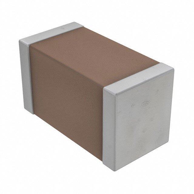
- 太阳诱电将投资9.5亿元在常州建新厂生产MLCC 预计2023年完工
- 英特尔发布欧洲新工厂建设计划 深化IDM 2.0 战略
- 台积电先进制程称霸业界 有大客户加持明年业绩稳了
- 达到5530亿美元!SIA预计今年全球半导体销售额将创下新高
- 英特尔拟将自动驾驶子公司Mobileye上市 估值或超500亿美元
- 三星加码芯片和SET,合并消费电子和移动部门,撤换高东真等 CEO
- 三星电子宣布重大人事变动 还合并消费电子和移动部门
- 海关总署:前11个月进口集成电路产品价值2.52万亿元 增长14.8%

PDF Datasheet 数据手册内容提取
Energy-saving fans version 2012-10 with ESM, ACi and iQ/iQ2-motor The engineer’s choice
The new generation of energy-saving fans Energy savings have become an important topic in almost every aspect of life. Our extended energy saving fan series, based on the energy saving motor (ESM) and the iQ-motor, offers high efficiency throughout a long service life and a significant decrease in energy consumption along with it. This is precisely what is required for refrigeration systems, such as in refrigerated and freezer cases or for condensing units. Comprehensive series The series of these energy saving fans includes the compact fan series of ACi 4400 as well as based on the energy saving motor (ESM), axial fans and centrifugal modules as well as the iQ-motor as an energy saving variant of the Q-motor. Axial fans are available in sizes of 130, 172, 200, 230, 250 and 300 mm plus the compact fan ACi 4400 with the dimensions 119 x 119 x 38 mm. With their new rotors and wall rings, which have been optimised according to aerodynamic criteria, the fans now work even more quietly and require no varnish, a particularly environmentally friendly feature. Energy saving centrifugal modules are available in sizes of 190 and 220 mm. These are especially appealing due to their compact and aerodynamically optimised design, which allows customers to install them quickly and hassle-free. The K1G200 energy saving centrifugal module in a diagonal impeller design rounds out the ESM series. It particularly distinguishes itself due to noise-optimised and air flow-optimised performance in the medium pressure range. ebm-papst sets the benchmark here, too. The existing series was expanded with additional versions and functions to meet new market de- mands. Among other things, this includes a 24 VDC design with an integrated 0-10 VDC open loop speed control and a speed monitoring output. A 0-10 VDC open loop speed control is now possible even for the existing line-fed designs by using an ESM+ plug-in module. This series is supplemented by the energy saving iQ-motor based on ebm-papst's GreenTech EC technology. The iQ2series further expands the offering with additional functions. Due to its dimen- sions and mounting options, which are identical to the Q-motor already established on the market, customers are given the possibility of a 1:1 replacement without extensive renovations. The iQ-motor can be readily installed with normal axial impellers with a 154 to 254 mm diameter. Maximum efficiency Our fans and motors achieve a maximum motor efficiency of over 70% and thus only need 1/3 to 1/6 of the power of an otherwise normal shaded-pole motor. Higher efficiency also means lower int- rinsic heating during operation at the same time, which dissipates less heat into the surrounding area. This means that less cooling power must be generated, thus resulting in additional energy savings. 2
Table of contents The new generation of energy-saving fans 2 Green Tech: The Green Company 4 Energy-saving axial fans 6 Energy-saving centrifugal modules 32 ESM/ACi accessories 40 ESM electrical connections 46 iQ/iQ2-motor 48 iQ/iQ2-motor accessories 58 Technical parameters & scope 62 ebm-papst representatives & subsidiaries 66 3
Sustainability is at the centre of our thoughts and actions. Out of conviction! Eco-friendliness and sustainability have always been at the core of our thoughts and actions. For decades, we have worked according to the simple but strict creed of our co-founder Gerhard Sturm: “Each new product we develop has to be better than the last one in terms of economy and ecology.” GreenTech is the ultimate expression of our corporate philosophy.
GreenTech is pro-active development. GreenTech is acknowledged and certified. Even in the design phase, the materials and processes we use are optimi- Every step in our chain of production meets the stringent standards of sed for the greatest possible eco-friendliness, energy balance and – environmental specialists and the public. The 2008 Environmental Prize wherever possible – recyclability. We continually improve the material of Baden-Wuerttemberg, the Green Award 2009, the Energy Efficiency and performance of our products, as well as the flow and noise charac- Award 2009 of the dena – to give just a few examples – testify to this. teristics. At the same time, we significantly reduce energy consumption. The environmental advantage gained in the performance of the products Close co-operation with universities and scientific institutes and the pro- developed from our GreenTech philosophy can also be measured in the fessorship we endow in the area of power engineering and regenerative fulfilment of the most stringent energy and environmental standards. energies allows us to profit from the latest research findings in these In many instances, our products are already well below the thresholds fields – and at the same time ensure highly qualified young academics. energy legislation will impose a few years from now – several times over. GreenTech is eco-friendly production. Our customers profit from this every day. GreenTech also stands for maximum energy efficiency in our production The heart of GreenTech is future-oriented EC technology from ebm- processes. There, the intelligent use of industrial waste heat and ground- papst. The EC technology at the core of our most efficient motors and water cooling, photovoltaics and, of course, our own cooling and venti - fans allows efficiency of up to 90%, saves energy at a very high level, lation technology are of the utmost importance. Our most modern plant, significantly extends service life and makes our products maintenance- for instance, consumes 91% less energy than currently specified and free. These values pay off not only for the environment, but every cent al- required. In this way, our products contribute to protecting the environ- so pays off for the user! All ebm-papst products – even those for which ment, from their origin to their recyclable packaging. GreenTech EC technology does not (yet) make sense from an application viewpoint – feature the greatest possible connection of economy and ecology. 5
Series: The existing series of energy saving axial fans was expanded by adding the ACi 4400 series and a compact fan with size 130. In addition, the ESM series is now available as a 24 VDC version with an integrated 0-10 VDC open loop speed control output and a speed monitoring signal. These control options have also become possible for line-fed designs via an additional ESM+ plug-in module. System: Not just our existing shaded-pole motors were replaced by high-efficiency GreenTech EC motors for our fans, but a complete new system was developed as a whole consisting of an EC motor, impeller and wall ring. Optimum efficiency for the best possible noise behaviour was only able to be achieved by having all of the components perfectly harmonised together. Energy efficiency: The energy saving motors achieve a maximum efficiency of over 70%. So they only need 1/3 to 1/6 the power of an otherwise normal shaded-pole motor. But higher efficiency also means lower intrinsic heating during operation at the same time, which dissipates less heat into the surrounding area. This results in further energy savings, since less cooling capacity needs to be put in place from the beginning. Easy installation: Effort needed by the customer for installation and logistics is reduced to a mini- mum due to the complete system. In addition to the fan itself, only screws are needed for mounting. Further savings result from the pluggable connection line. For example, this allows installation time to be drastically reduced due to a pre-installed cable harness. The number of variants can be sub- stantially reduced by subsequent programming as well by having different air performance levels customised accordingly – even at a later point in time. An earth wire can be omitted due to a design in protection class 2. Robust design (ESM): Ten years of field experience with more than 3 million energy saving motors shows that the system is robust, maintenance-free and durable. Depending on environmental condi- tions, the service life usually exceeds 60,000 hours. The stator, which is hermetically sealed with a coat of plastic, is optimally protected from ambient influences. And the electronics are protected from humidity with a sealed off cover, so that IP 54 protection requirements are fulfilled. Shock loads of more than 50g have no effect on the fan due to the stable design. Certifications: ACi 4400: UL (507), VDE (EN 60950), CSA ESM: All of the approvals required in the refrigerated case industry are present or in progress. VDE: EN 60335-1, -2-24, -2-80, -2-89 UL 1004-1, 1004-3, UL 60730 and GOST 6
The new energy-saving axial fans ACI 4400 8 ESM Size 130, 172 10 ESM Size 200, 230, 250 14 ESM Size 300 28 7
Energy-saving axial fans Series ACi 4400 119 x 119 x 38 mm – Material: Housing: Plastic PBT – Bearings:Maintenance-free ball bearings fibreglass-reinforced – Motor protection:Via electronics Blade: Plastic PA, – Moisture protection:Motor and circuit fibreglass-reinforced board are coated – Number of blades:5 – Electrical connection:Plug-in connection – Direction of air flow: lateral "V", exhaust over struts – Protection class:II – Direction of rotation:Clockwise, seen – Product conforming to standard:CE on rotor – Approvals:UL (507), VDE (EN 60950), – Insulation class:"E" CSA – Mounting position:Any – Condensate discharges:None – Mode of operation:Con. operation (S1) el Nominal data Curve Nominal voltage Nominal voltagerange Frequency Speed/rpm Input power Current draw Sound pressure lev Sound power level Perm. amb. temp. Mass Type VAC VAC Hz rpm W mA dB(A) Bel(A) °C kg ACi 4420 ML A 1~ 230 195...265 50/60 1850 1,4 17 25 4,1 -20..+75 0,25 ACi 4420 H B 1~ 230 195...265 50/60 3000 3,3 35 39 5,1 -20..+75 0,25 ACi 4420 HH C 1~ 230 195...265 50/60 3350 4,4 41 42 5,3 -20..+75 0,25 ACi 4410 HH D 1~ 115 85...132 50/60 3350 4,4 82 42 5,3 -20..+75 0,25 subject to alterations n P I Curves e rpm W mA Pa in HO2 Aasir ppeerr:f oISrmO a5n8c0e1 m,easured AA 12 11885500 11,,45 1178 Installation category A, 70 D and without protection against A 3 1850 1,6 19 C accidental contact A 4 1850 1,7 19 60 B 1 3000 3,3 35 The acoustic values given are only valid under the measur- B 2 3000 3,9 39 B ment conditions listed and B 3 3000 3,9 44 50 0,2 may vary depending on the B 4 3000 4,7 46 installation situation. C 1 3350 4,4 41 40 With any deviation to the stan- C 2 3350 5,1 48 4 dard setup, the specific values C 3 3350 5,7 53 have to be checked and re- 30 4 viewed once installed or fitted! C 4 3350 5,9 55 0,1 A 3 3 For detailed information DD 12 33335500 45,,41 8926 20 see Compact fans catalogue 2 version 2011, p. 8-16 D 3 3350 5,7 106 2 D 4 3350 5,9 110 4 10 3 2 1 1 1 pfs 0 20 40 60 80 100 cfm qV 25 50 75 100 125 150 175 m3/h 8
– Electr. connection: L ACi 4400 N 119±0.3 104.8±0.2 A-A 38±0.5 A 6 ±0.3 3 0. Ø4.3±0.15 R A 6 ±0.3 R 0.3 Ø4.3±0.15 "B" "A" ❮ "V" Plug connection on both sides possible. 9 Accessories p. 44 ff.
Energy-saving axial fans Ø 130 – Material: Wall ring: Plastic PP, fibreglass- – Bearings:Maintenance-free ball bearings reinforced; Blade:Plastic PA, – Motor protection:Via electronics and fibreglass-reinforced TOP – Number of blades:7 – Electrical connection:Plug-in connection – Direction of air flow: on motor side "V", exhaust over struts – Protection class:II – Direction of rotation:Counter-clockwise, – Product conforming to standard:CE; seen on rotor EN 60335-1 – Type of protection:IP 54 – Approvals:VDE, UL, CSA, GOST are – Insulation class:"B" applied for – Mounting position:Any – Speed:Using the programming unit, 2 – Condensate discharges:None speeds between n and n can be min max – Mode of operation:Con. operation (S1) programmed. e Nominal data Curve Nominal voltage Frequency (1)Speed/rpm Max. input power(1) Max. current draw(1) Max. back pressur Perm. amb. temp. Mass Type Motor VAC Hz rpm W A Pa °C kg W1G130-AA49-01 M1G055-AI A 1~ 115 50/60 3200 24 0,38 90 -30..+60 0,75 W1G130-AA25-01 M1G055-AI B 1~ 230 50/60 3200 24 0,19 90 -30..+70 0,75 subject to alterations (1)Nominal data in operating point with maximum load and 115 or 230 VAC n P I L A Curves e W rpm W A dB(A) Pa in HO2 AB Aasir ppeerr:f oISrmO a5n8c0e1 m,easured AA 12 33220000 2234 00,,3388 6631 90 4 Installation category A, in ebm-papst full nozzle A 3 3200 24 0,38 60 and without protection against A 4 3200 24 0,38 63 80 accidental contact 0,3 A 5 2800 16 0,26 60 70 8 Suction-side noise levels: A 6 2800 16 0,26 58 LWA as per ISO 13347, A 7 2800 16 0,26 57 60 3 LpA measured at 1 m distance A 8 2800 16 0,26 60 to fan axis B 1 3200 23 0,19 63 50 0,2 7 The acoustic values given are B 2 3200 24 0,19 61 only valid under the measur- B 3 3200 24 0,19 60 ment conditions listed and 40 B 4 3200 24 0,19 63 may vary depending on the installation situation. B 5 2800 16 0,13 60 30 2 B 6 2800 16 0,13 58 20 0,1 6 dWairthd asentyu dpe, vthiaet isopne tcoi fitch ev asltuaens- B 7 2800 16 0,13 57 have to be checked and re- B 8 2800 16 0,13 60 viewed once installed or fitted! 10 For detailed information 5 1 see page 62 ff. pfs 0 40 80 120 160 200 cfm qV 50 100 150 200 250 300 350 m3/h nmax. = 3200 min-1 n = 2800 min-1 nmin. = 1100 min-1 10
– Electr. connection: L1 black Mains supply Energy-saving voltage blue motor / fan N (ESM) Speed selection brown L1 or N S S off on (L1 or N) Speed selection n1 n2 A-A Ø151±0.5 1.5 10 5 Ø 58-1 4.2±0.1 Ø 55±0.3 1.5 10 Ø17Ø21±60.2+50-.01.3 A Ø4.2±0.1Ø5 A +20 0 ❮ "V" 45 ±5 0 4 6 Connection lead (total length 450 mm) is fitted ex works and can be detached. 11 Handheld Pro- grammer p. 41
Energy-saving axial fans Ø 172 – Material: Wall ring: Plastic PP – Bearings:Maintenance-free ball bearings Blade:Plastic PA, – Motor protection:Via electronics and fibreglass-reinforced TOP – Number of blades:5 – Electrical connection:Plug-in connection – Direction of air flow: on motor side "V", exhaust over struts – Protection class:II – Direction of rotation:Counter-clockwise, – Product conforming to standard:CE seen on rotor – Approvals:VDE, UL, CSA, GOST – Type of protection:IP 54 – Speed:Using the programming unit, 2 – Insulation class:"B" speeds between n and n can be min max – Mounting position:Any programmed. – Condensate discharges:None – Mode of operation:Con. operation (S1) e Nominal data Curve Nominal voltage Frequency (1)Speed/rpm Max. input power(1) Max. current draw(1) Max. back pressur Perm. amb. temp. Mass Type Motor VAC Hz rpm W A Pa °C kg W1G172-EC95 -01 M1G055-BD A 1~ 115 50/60 2500 21 0,30 60 -30..+50 0,95 W1G172-EC91 -01 M1G055-BD B 1~ 230 50/60 2500 22 0,18 60 -30..+50 0,95 subject to alterations (1)Nominal data in operating point with maximum load and 115 or 230 VAC n P I L A Curves e W rpm W A dB(A) Pa in HO2 AB Aasir ppeerr:f oISrmO a5n8c0e1 m,easured AA 12 22550000 2201 00,,2380 6623 Installation category A, 60 0,24 4 iann de bwmit-hpoaupts pt rfoutlel cntoioznzl eagainst AA 34 22550000 2211 00,,3300 6633 accidental contact A 5 1700 9 0,14 54 50 0,20 Suction-side noise levels: A 6 1700 10 0,16 53 LWA as per ISO 13347, A 7 1700 10 0,16 53 LpA measured at 1 m distance A 8 1700 10 0,16 54 40 0,16 3 to fan axis B 1 2500 21 0,17 62 The acoustic values given are B 2 2500 22 0,18 63 30 0,12 8 omnelyn tv caolindd uitniodnesr tlihsete md eaansdur- BB 34 22550000 2222 00,,1188 6633 may vary depending on the installation situation. B 5 1700 9 0,07 54 20 0,08 7 2 With any deviation to the stan- B 6 1700 10 0,08 53 dard setup, the specific values B 7 1700 10 0,08 53 have to be checked and re- B 8 1700 10 0,08 54 10 0,04 6 viewed once installed or fitted! For detailed information 5 1 see page 62 ff. pfs 0 50 100 150 200 250 300 cfm qV 100 200 300 400 500 m3/h nmax. = 2500 min-1 n = 1700 min-1 nmin. = 900 min-1 12
– Electr. connection: L1 black Mains supply Energy-saving voltage blue motor / fan N (ESM) Speed selection brown L1 or N S S off on (L1 or N) Speed selection n1 n2 78.5 35 4x Ø4.3 2 9 1 Ø 2 8 2 7 0 2 1 2 2 Ø Ø Ø +20 0 5 4 4 0±5 4 6 ❮ "V" Connection lead (total length 450 mm) is fitted ex works and can be detached Other lengths available as accessory. 13 Accessories p. 40 ff.
Energy-saving axial fans Ø 200 – Material: Wall ring: A Plastic PP – Mode of operation:Con. operation (S1) B epylen – Bearings:Maintenance-free ball bearings Blade:Plastic PA, – Motor protection:Via electronics and fibreglass-reinforced TOP – Number of blades:5 – Electrical connection:Plug-in connection – Direction of air flow: on motor side "V", exhaust over struts – Protection class:II – Direction of rotation:Counter-clockwise, – Product conforming to standard:CE seen on rotor – Approvals:VDE, UL, CSA, GOST – Type of protection:IP 54 – Speed:Using the programming unit, 2 – Insulation class:"B" speeds between n and n can be min max – Mounting position:Any programmed. – Condensate discharges:None e Nominal data Curve Nominal voltage Frequency (1)Speed/rpm Max. input power(1) Max. current draw(1) Max. back pressur Perm. amb. temp. Mass Type Motor VAC Hz rpm W A Pa °C kg W1G200-EC91 -27 M1G055-BD A 1~ 115 50/60 1300 8,0 0,11 23 -30..+50 1,0 W1G200-EC87 -25 M1G055-BD B 1~ 230 50/60 1300 8,0 0,07 23 -30..+50 1,0 subject to alterations (1)Nominal data in operating point with maximum load and 115 or 230 VAC n P I L A Curves e W rpm W A dB(A) Pa in HO2 AB Aasir ppeerr:f oISrmO a5n8c0e1 m,easured AA 12 11330000 78 00,,0190 5409 Installation category A, in ebm-papst full nozzle A 3 1300 8 0,10 48 25 0,10 and without protection against A 4 1300 8 0,11 51 accidental contact A 5 900 3 0,05 41 4 Suction-side noise levels: A 6 900 4 0,05 41 20 0,08 LWA as per ISO 13347, A 7 900 4 0,05 40 3 LpA measured at 1 m distance A 8 900 4 0,05 41 to fan axis B 1 1300 7 0,06 50 15 0,06 The acoustic values given are B 2 1300 8 0,07 49 only valid under the measur- B 3 1300 8 0,07 48 ment conditions listed and B 4 1300 8 0,07 51 may vary depending on the 10 0,04 8 2 installation situation. B 5 900 3 0,03 41 7 B 6 900 4 0,04 41 With any deviation to the stan- dard setup, the specific values B 7 900 4 0,04 40 5 0,02 6 hviaevwee tdo obnec ceh iencsktaeldle dan odr rfeit-ted! B 8 900 4 0,04 41 For detailed information 5 1 see page 62 ff. pfs 0 50 100 150 200 250 cfm qV 100 200 300 400 m3/h nmax. = 1300 min-1 n = 900 min-1 nmin. = 500 min-1 14
– Electr. connection: L1 black Mains supply Energy-saving voltage blue motor / fan N (ESM) Speed selection brown L1 or N S S off on (L1 or N) Speed selection n1 n2 78.5 40 4x Ø4.3 0 2 2 Ø 0 6 0 0 3 5 2 2 2 Ø Ø Ø +20 0 5 4 ±5 4 40 6 ❮ "V" Connection lead (total length 450 mm) is fitted ex works and can be detached Other lengths available as accessory. 15 Accessories p. 40 ff.
Energy-saving axial fans Ø 200 – Material: Wall ring: Plastic PP – Bearings:Maintenance-free ball bearings Blade:Plastic PA, – Motor protection:Via electronics and fibreglass-reinforced TOP – Number of blades:5 – Electrical connection:Plug-in connection – Direction of air flow: on motor side "V", exhaust over struts – Protection class:II – Direction of rotation:Counter-clockwise, – Product conforming to standard:CE seen on rotor – Approvals:VDE, UL, CSA, GOST – Type of protection:IP 54 – Speed:Using the programming unit, 2 – Insulation class:"B" speeds between n and n can be min max – Mounting position:Any programmed. – Condensate discharges:None – Mode of operation:Con. operation (S1) e Nominal data Curve Nominal voltage Frequency (1)Speed/rpm Max. input power(1) Max. current draw(1) Max. back pressur Perm. amb. temp. Mass Type Motor VAC Hz rpm W A Pa °C kg W1G200-EC95 -47 M1G055-BD A 1~ 115 50/60 2100 31 0,46 55 -30..+50 1,0 W1G200-EC91 -45 M1G055-BD B 1~ 230 50/60 2100 31 0,24 55 -30..+50 1,0 subject to alterations (1)Nominal data in operating point with maximum load and 115 or 230 VAC n P I L A Curves e W rpm W A dB(A) Pa in HO2 AB Aasir ppeerr:f oISrmO a5n8c0e1 m,easured AA 12 22110000 2380 00,,4425 6621 Installation category A, 60 0,24 iann de bwmit-hpoaupts pt rfoutlel cntoioznzl eagainst AA 34 22110000 3311 00,,4466 6602 4 accidental contact A 5 1500 14 0,22 54 50 0,20 Suction-side noise levels: A 6 1500 15 0,22 54 LWA as per ISO 13347, A 7 1500 16 0,26 53 LpA measured at 1 m distance A 8 1500 16 0,26 55 40 0,16 3 to fan axis B 1 2100 29 0,22 62 The acoustic values given are B 2 2100 30 0,23 61 30 0,12 8 omnelyn tv caolindd uitniodnesr tlihsete md eaansdur- BB 34 22110000 3311 00,,2244 6602 may vary depending on the installation situation. B 5 1500 14 0,11 54 20 0,08 7 2 With any deviation to the stan- B 6 1500 16 0,12 54 dard setup, the specific values B 7 1500 16 0,13 53 have to be checked and re- B 8 1500 16 0,13 55 10 0,04 6 viewed once installed or fitted! For detailed information 5 1 see page 62 ff. pfs 0 50 100 150 200 250 300 350 400 cfm qV 100 200 300 400 500 600 700 m3/h nmax. = 2100 min-1 n = 1500 min-1 nmin. = 800 min-1 16
– Electr. connection: L1 black Mains supply Energy-saving voltage blue motor / fan N (ESM) Speed selection brown L1 or N S S off on (L1 or N) Speed selection n1 n2 78.5 40 4x Ø4.3 0 2 2 Ø 0 6 0 0 3 5 2 2 2 Ø Ø Ø +20 0 5 4 ±5 4 40 6 ❮ "V" Connection lead (total length 450 mm) is fitted ex works and can be detached Other lengths available as accessory. 17 Accessories p. 40 ff.
Energy-saving axial fans Ø 200 – Material: Wall ring: epylen – Bearings:Maintenance-free ball bearings Blade:Plastic PA, – Motor protection:Via electronics and fibreglass-reinforced TOP – Number of blades:5 – Electrical connection:Plug-in connection – Direction of air flow: on motor side "V", exhaust over struts – Protection class:II – Direction of rotation:Counter-clockwise, – Approvals:VDE, UL, CSA, GOST are seen on rotor applied for – Type of protection:IP 54 – Technical features:Control input 0-10 – Insulation class:"B" VDC / PWM, Tach output – Mounting position:Any – Condensate discharges:None – Mode of operation:Con. operation (S1) e Nominal data Curve Nominal voltage Nominalvoltage range (1)Speed/rpm (1)Input power (1)current draw Max. back pressur Perm. amb. temp. Mass Type Motor VDC VDC rpm W A Pa °C kg W1G200-EF41 -01 M1G055-BD A 24 16-28 1550 11 0,50 30 -30..+50 1,0 W1G200-EF01 -01 M1G055-BD B 24 16-28 2130 29 1,50 55 -30..+50 1,0 subject to alterations (1)Nominal data running at free air. n P I L A Curves e W rpm W A dB(A) Pa Oin H2 Aasir ppeerr:f oISrmO a5n8c0e1 m,easured AA 12 11555300 1111 00,,5500 5543 Installation category A, 70 0,28 in ebm-papst full nozzle A 3 1510 11 0,51 52 and without protection against A 4 1515 11 0,51 55 accidental contact 60 0,24 B 1 2130 29 1,50 62 Suction-side noise levels: B 2 2085 30 1,56 62 4 B LWA as per ISO 13347, B 3 2050 31 1,61 61 50 0,20 LpA measured at 1 m distance B 4 2050 31 1,62 59 to fan axis 40 0,16 3 The acoustic values given are only valid under the measur- ment conditions listed and 30 0,12 4 A may vary depending on the installation situation. 20 0,08 3 2 With any deviation to the stan- dard setup, the specific values have to be checked and re- 10 0,04 2 viewed once installed or fitted! For detailed information 1 1 see page 62 ff. pfs 0 100 200 300 400 500cfm qV 100 200 300 400 500 600 700 800 m3/h 18
– Electr. connection: UN +24 VDC 1 UB PWM/0-10 VDC 4 RE>100K Tacho 3 680 R 47 V Tacho GND 2 GND1 Reverse-polarity protection 78.5 40 4xØ4.3 0 2 2 Ø 0 6 0 0 3 5 2 2 2 Ø Ø Ø +20 0 5 4 ±5 4 40 6 ❮ "V" Connection lead (total length 450 mm) is fitted ex works and can be detached Other lengths available as accessory. 19 Accessories Electr. connection p. 41 p. 46
Energy-saving axial fans Ø 200 – Material: Wall ring: epylen – Bearings:Maintenance-free ball bearings Blade:Plastic PA, – Motor protection:Via electronics and fibreglass-reinforced TOP – Number of blades:5 – Electrical connection:Plug-in connection – Direction of air flow: on motor side "V", exhaust over struts – Protection class:II – Direction of rotation:Counter-clockwise, – Product conforming to standard:CE; seen on rotor EN 60335-1 – Type of protection:IP 54 – Approvals:VDE, UL, CSA, GOST are – Insulation class:"B" applied for – Mounting position:Any – Technical features:Control input 0-10 – Condensate discharges:None VDC / PWM, Output 10 VDC max. 1.1 mA, – Mode of operation:Con. operation (S1) Tach output e Nominal data Curve Nominal voltage Frequency (1)Speed/rpm Max. input power(1) Max. current draw(1) Max. back pressur Perm. amb. temp. Mass Type Motor VAC Hz rpm W A Pa °C kg W1G200-EC87 -A2 M1G055-BD A 1~ 230 50/60 1300 8 0,07 23 -30..+50 1,0 W1G200-EC91 -A4 M1G055-BD B 1~ 230 50/60 2100 31 0,24 55 -30..+50 1,0 subject to alterations (1)Nominal data in operating point with maximum load and 115 or 230 VAC n P I L A Curves e W rpm W A dB(A) Pa in HO2 Aasir ppeerr:f oISrmO a5n8c0e1 m,easured AA 12 11330000 78,,00 00,,0067 5409 4 Installation category A, in ebm-papst full nozzle A 3 1300 8,0 0,07 48 50 0,20 and without protection against A 4 1300 8,0 0,07 48 accidental contact B 1 2100 29 0,23 62 B Suction-side noise levels: B 2 2100 30 0,24 62 40 0,16 3 LWA as per ISO 13347, B 3 2100 31 0,24 60 LpA measured at 1 m distance B 4 2100 31 0,24 59 to fan axis 30 0,12 The acoustic values given are only valid under the measur- ment conditions listed and 4 may vary depending on the 20 0,08 2 installation situation. 3 With any deviation to the stan- dard setup, the specific values 10 0,04 A 2 hviaevwee tdo obnec ceh iencsktaeldle dan odr rfeit-ted! For detailed information 1 1 see page 62 ff. pfs 0 100 200 300 400 cfm qV 100 200 300 400 500 600 700 m3/h 20
– Electr. connection: CON10 L AC1 1 P N 1.25A AC2 2 N CON50 +10V 1 Imax=1.1mA 10V/PWM 3 47k 47k 100μF GND 4 Tacho 2 1 680R ZMM47 2 105.5 78.5 40 Ø4.3(4x) 0 2 2 Ø 060 035 222 ØØØ 4 ❮ "V" +20 0 5 0+20 6 0±5 4 0 4 0 1 ±5 06 4 21 Accessories Electr. connection p. 40 ff. p. 47
Energy-saving axial fans Ø 200 – Material: Blade:Plastic PA, – Bearings:Maintenance-free ball bearings fibreglass-reinforced – Motor protection:Via electronics and Guard grille: epylen TOP – Number of blades:5 – Electrical connection:Plug-in connection – Direction of air flow:"A", intake over on motor side guard grille – Protection class:II – Direction of rotation:Counter-clockwise, – Product conforming to standard:CE seen on rotor – Approvals:VDE, UL, CSA, GOST – Type of protection:IP 54 – Speed:Using the programming unit, 2 – Insulation class:"B" speeds between n and n can be min max – Mounting position:Any programmed. – Condensate discharges:None – Mode of operation:Con. operation (S1) e Nominal data Curve Nominal voltage Frequency (1)Speed/rpm Max. input power(1) Max. current draw(1) Max. back pressur Perm. amb. temp. Mass Type Motor VAC Hz rpm W A Pa °C kg S1G200-CA95-02 M1G055-BD A 1~ 115 50/60 2000 31 0,43 45 -30..+50 0,95 S1G200-CA91-02 M1G055-BD B 1~ 230 50/60 2000 34 0,26 45 -30..+50 0,95 subject to alterations (1)Nominal data in operating point with maximum load and 115 or 230 VAC n P I L A Curves e W rpm W A dB(A) Pa in HO2 AB Aasir ppeerr:f oISrmO a5n8c0e1 m,easured AA 12 22000000 3300 00,,4433 6644 Installation category A, in ebm-papst short nozzle A 3 2000 30 0,43 63 50 0,20 and with protection against A 4 2000 31 0,43 64 accidental contact A 5 1500 17 0,28 59 4 Suction-side noise levels: A 6 1500 18 0,28 58 40 0,16 LWA as per ISO 13347, A 7 1500 19 0,28 58 LpA measured at 1 m distance A 8 1500 20 0,28 59 to fan axis B 1 2000 32 0,24 64 30 0,12 3 The acoustic values given are B 2 2000 33 0,25 64 8 only valid under the measur- B 3 2000 33 0,25 63 ment conditions listed and B 4 2000 34 0,26 64 may vary depending on the 20 0,08 installation situation. B 5 1500 18 0,16 59 7 B 6 1500 19 0,16 58 2 With any deviation to the stan- dard setup, the specific values B 7 1500 19 0,16 58 10 0,04 6 hviaevwee tdo obnec ceh iencsktaeldle dan odr rfeit-ted! B 8 1500 20 0,16 59 For detailed information 5 1 see page 62 ff. pfs 0 50 100 150 200 250 300 350 400 cfm qV 100 200 300 400 500 600 700 m3/h nmax. = 2000 min-1 n = 1500 min-1 nmin. = 800 min-1 22
– Electr. connection: L1 black Mains supply Energy-saving voltage blue motor / fan N (ESM) Speed selection brown L1 or N S S off on (L1 or N) Speed selection n1 n2 40 38.5 3 4x Ø6.5 0 08 0 67 2 22 Ø ØØ 37.5 ±20 3800±5 4 "A"❯ 6 Connection lead (total length 450 mm) is fitted ex works and can be detached Other lengths available as accessory. 23 Accessories p. 40 ff.
Energy-saving axial fans Ø 230 – Material: Wall ring: Plastic PP – Bearings:Maintenance-free ball bearings Blade:Plastic PA, – Motor protection:Via electronics and fibreglass-reinforced TOP – Number of blades:5 – Electrical connection:Plug-in connection – Direction of air flow: on motor side "V", exhaust over struts – Protection class:II – Direction of rotation:Counter-clockwise, – Product conforming to standard:CE seen on rotor – Approvals:VDE, UL, CSA, GOST – Type of protection:IP 54 – Speed:Using the programming unit, 2 – Insulation class:"B" speeds between n and n can be min max – Mounting position:Any programmed. – Condensate discharges:None – Mode of operation:Con. operation (S1) e Nominal data Curve Nominal voltage Frequency (1)Speed/rpm Max. input power(1) Max. current draw(1) Max. back pressur Perm. amb. temp. Mass Type Motor VAC Hz rpm W A Pa °C kg W1G230-EB97 -01 M1G055-BD A 1~ 115 50/60 1500 23 0,35 36 -30..+50 1,05 W1G230-EB89 -01 M1G055-BD B 1~ 230 50/60 1500 26 0,20 36 -30..+50 1,05 subject to alterations (1)Nominal data in operating point with maximum load and 115 or 230 VAC n P I L A Curves e W rpm W A dB(A) Pa in HO2 AB Aasir ppeerr:f oISrmO a5n8c0e1 m,easured AA 12 11550000 2233 00,,3355 5588 Installation category A, in ebm-papst full nozzle A 3 1500 23 0,35 58 and without protection against A 4 1500 23 0,35 57 40 0,16 accidental contact A 5 1000 9 0,15 48 4 Suction-side noise levels: A 6 1000 10 0,16 48 LWA as per ISO 13347, A 7 1000 10 0,16 48 30 0,12 3 Ltop Afa mn eaaxsisured at 1 m distance A 8 1000 10 0,16 48 B 1 1500 24 0,19 58 The acoustic values given are B 2 1500 25 0,19 58 only valid under the measur- B 3 1500 25 0,19 58 20 0,08 mmeayn tv caoryn ddietipoenns dliisntge do na nthde B 4 1500 26 0,20 57 8 installation situation. B 5 1000 10 0,09 48 2 B 6 1000 11 0,09 48 7 With any deviation to the stan- 10 0,04 dhaarvde stoe tbuep ,c thheec skpeedc aifnicd vrael-ues BB 78 11000000 1111 00,,1100 4488 6 viewed once installed or fitted! For detailed information 5 1 see page 62 ff. pfs 0 100 200 300 400 500 cfm qV 200 400 600 800 m3/h nmax. = 1500 min-1 n = 1000 min-1 nmin. = 700 min-1 24
– Electr. connection: L1 black Mains supply Energy-saving voltage blue motor / fan N (ESM) Speed selection brown L1 or N S S off on (L1 or N) Speed selection n1 n2 78.5 50 4x Ø4.3 0 5 2 Ø 0 6 0 3 6 8 2 2 2 Ø Ø Ø +20 0 5 4 4 0±5 4 6 ❮ "V" Connection lead (total length 450 mm) is fitted ex works and can be detached Other lengths available as accessory. 25 Accessories p. 40 ff.
Energy-saving axial fans Ø 250 – Material: Wall ring: Plastic PP – Bearings:Maintenance-free ball bearings Blade:Plastic PA, – Motor protection:Via electronics and fibreglass-reinforced TOP – Number of blades:5 – Electrical connection:Plug-in connection – Direction of air flow: on motor side "V", exhaust over struts – Protection class:II – Direction of rotation:Counter-clockwise, – Product conforming to standard:CE seen on rotor – Approvals:VDE, UL, CSA, GOST – Type of protection:IP 54 – Speed:Using the programming unit, 2 – Insulation class:"B" speeds between n and n can be min max – Mounting position:Any programmed. – Condensate discharges:None – Mode of operation:Con. operation (S1) e Nominal data Curve Nominal voltage Frequency (1)Speed/rpm Max. input power(1) Max. current draw(1) Max. back pressur Perm. amb. temp. Mass Type Motor VAC Hz rpm W A Pa °C kg W1G250-BB21-01 M1G055-BI A 1~ 115 50/60 1700 32 0,47 40 -30..+50 1,55 W1G250-BB17-01 M1G055-BI B 1~ 230 50/60 1700 32 0,24 40 -30..+50 1,55 subject to alterations (1)Nominal data in operating point with maximum load and 115 or 230 VAC n P I L A Curves e W rpm W A dB(A) Pa in HO2 AB Aasir ppeerr:f oISrmO a5n8c0e1 m,easured AA 12 11770000 3301 00,,4445 6623 Installation category A, in ebm-papst full nozzle A 3 1700 32 0,47 64 and with protection against A 4 1700 32 0,47 65 40 0,16 4 accidental contact A 5 1200 14 0,22 53 Suction-side noise levels: A 6 1200 15 0,24 54 LWA as per ISO 13347, A 7 1200 16 0,25 55 30 0,12 3 Ltop Afa mn eaaxsisured at 1 m distance A 8 1200 17 0,26 57 B 1 1700 30 0,24 62 The acoustic values given are B 2 1700 31 0,24 63 8 only valid under the measur- B 3 1700 32 0,24 64 20 0,08 mmeayn tv caoryn ddietipoenns dliisntge do na nthde B 4 1700 32 0,24 65 7 installation situation. B 5 1200 14 0,12 53 2 B 6 1200 15 0,13 54 With any deviation to the stan- 10 0,04 dhaarvde stoe tbuep ,c thheec skpeedc aifnicd vrael-ues BB 78 11220000 1167 00,,1144 5557 6 viewed once installed or fitted! For detailed information 5 1 see page 62 ff. pfs 0 100 200 300 400 500 cfm qV 200 400 600 800 1000 m3/h nmax. = 1700 min-1 n = 1200 min-1 nmin. = 900 min-1 26
– Electr. connection: L1 black Mains supply Energy-saving voltage blue motor / fan N (ESM) Speed selection brown L1 or N S S off on (L1 or N) Speed selection n1 n2 92 296 80 4x90˚ 4 45˚ 7 Ø x 4 0 0 8 5 2 2 Ø Ø Ø31Ø5295 40±5 6 ❮ "V" 340±20 27 Accessories p. 40 ff.
Energy-saving axial fans Ø 300 – Material: Wall ring: Plastic PP – Bearings:Maintenance-free ball bearings Blade:Plastic PA, – Motor protection:Via electronics and fibreglass-reinforced TOP – Number of blades:5 – Electrical connection:Plug-in connection – Direction of air flow: on motor side "V", exhaust over struts – Protection class:II – Direction of rotation:Counter-clockwise, – Product conforming to standard:CE seen on rotor – Approvals:VDE, UL, CSA, GOST – Type of protection:IP 54 – Speed:Using the programming unit, 2 – Insulation class:"B" speeds between n and n can be min max – Mounting position:Any programmed. – Condensate discharges:None – Mode of operation:Con. operation (S1) e Nominal data Curve Nominal voltage Frequency (1)Speed/rpm Max. input power(1) Max. current draw(1) Max. back pressur Perm. amb. temp. Mass Type Motor VAC Hz rpm W A Pa °C kg W1G300-BB23-01 M1G055-BI A 1~ 115 50/60 1300 35 0,50 35 -30..+50 1,75 W1G300-BB19-01 M1G055-BI B 1~ 230 50/60 1300 35 0,27 35 -30..+50 1,75 subject to alterations (1)Nominal data in operating point with maximum load and 115 or 230 VAC n P I L A Curves e W rpm W A dB(A) Pa in HO2 AB Aasir ppeerr:f oISrmO a5n8c0e1 m,easured AA 12 11330000 2381 00,,4416 5588 Installation category A, 35 0,14 4 in ebm-papst full nozzle A 3 1300 32 0,47 57 and with protection against A 4 1300 35 0,50 58 accidental contact 30 0,12 Suction-side noise levels: AA 56 990000 1124 00,,2245 5409 3 LWA as per ISO 13347, A 7 900 15 0,26 49 25 0,10 LpA measured at 1 m distance A 8 900 16 0,27 50 to fan axis B 1 1300 32 0,25 58 20 0,08 The acoustic values given are B 2 1300 34 0,27 58 only valid under the measur- B 3 1300 34 0,27 57 8 ment conditions listed and 15 0,06 2 may vary depending on the B 4 1300 35 0,27 58 installation situation. B 5 900 13 0,12 50 7 B 6 900 14 0,13 49 10 0,04 dWairthd asentyu dpe, vthiaet isopne tcoi fitch ev asltuaens- B 7 900 15 0,14 49 6 have to be checked and re- B 8 900 16 0,15 50 5 0,02 viewed once installed or fitted! For detailed information 5 1 see page 62 ff. pfs 0 100 200 300 400 500 600 700 800 cfm qV 200 400 600 800 1000 1200 m3/h nmax. = 1300 min-1 n = 900 min-1 nmin. = 700 min-1 28
– Electr. connection: L1 black Mains supply Energy-saving voltage blue motor / fan N (ESM) Speed selection brown L1 or N S S off on (L1 or N) Speed selection n1 n2 92 360 80 4x90˚ 4 45˚ 3 6. Ø x 4 0 0 5 0 3 3 Ø Ø Ø3Ø93780 40±56 ❮ "V" 290±20 29 Accessories p. 40 ff.
Energy-saving axial fans Ø 300 – Material: Blade:Plastic PA, – Bearings:Maintenance-free ball bearings fibreglass-reinforced – Motor protection:Via electronics and Guard grille: epylen TOP – Number of blades:5 – Electrical connection:Plug-in connection – Direction of air flow:"A", intake over on motor side guard grille – Protection class:II – Direction of rotation:Counter-clockwise, – Product conforming to standard:CE seen on rotor – Approvals:VDE, UL, CSA, GOST – Type of protection:IP 54 – Speed:Using the programming unit, 2 – Insulation class:"B" speeds between n and n can be min max – Mounting position:Any programmed. – Condensate discharges:None – Mode of operation:Con. operation (S1) e Nominal data Curve Nominal voltage Frequency (1)Speed/rpm Max. input power(1) Max. current draw(1) Max. back pressur Perm. amb. temp. Mass Type Motor VAC Hz rpm W A Pa °C kg S1G300-CA23-02 M1G055-BI A 1~ 115 50/60 1250 35 0,56 35 -30..+50 1,4 S1G300-CA19-02 M1G055-BI B 1~ 230 50/60 1250 35 0,27 35 -30..+50 1,4 subject to alterations (1)Nominal data in operating point with maximum load and 115 or 230 VAC n P I L A Curves e W rpm W A dB(A) Pa in HO2 AB Aasir ppeerr:f oISrmO a5n8c0e1 m,easured AA 12 11225500 3312 00,,4457 6642 Installation category A, in ebm-papst short nozzle A 3 1250 32 0,48 62 and with protection against A 4 1250 35 0,56 63 40 0,16 accidental contact A 5 900 13 0,24 55 4 Suction-side noise levels: A 6 900 14 0,26 54 LWA as per ISO 13347, A 7 900 16 0,30 53 30 0,12 Ltop Afa mn eaaxsisured at 1 m distance A 8 900 17 0,32 54 B 1 1250 27 0,21 64 3 The acoustic values given are B 2 1250 30 0,23 62 only valid under the measur- B 3 1250 32 0,24 62 20 0,08 mmeayn tv caoryn ddietipoenns dliisntge do na nthde B 4 1250 35 0,27 63 8 installation situation. B 5 900 13 0,12 55 2 B 6 900 14 0,13 54 7 With any deviation to the stan- 10 0,04 dhaarvde stoe tbuep ,c thheec skpeedc aifnicd vrael-ues BB 78 990000 1176 00,,1156 5534 6 viewed once installed or fitted! For detailed information see page 62 ff. 5 1 pfs 0 100 200 300 400 500 600 700 cfm qV 200 400 600 800 1000 1200m3/h nmax. = 1250 min-1 n = 900 min-1 nmin. = 700 min-1 30
– Electr. connection: L1 black Mains supply Energy-saving voltage blue motor / fan N (ESM) Speed selection brown L1 or N S S off on (L1 or N) Speed selection n1 n2 45 43 3 4x Ø6.5 Ø300 Ø360Ø377 38 330±20 40±5 "A"❯ 6 Connection lead (total length 450 mm) is fitted ex works and can be detached Other lengths available as accessory. 31 Accessories p. 40 ff.
The perfect combination! For the new energy saving centrifugal modules, we have combined a backward curved centrifugal impeller already established on the market with new compact modules. The result is a highly com- pact unit with an integrated inlet nozzle and motor suspension directly connected to the mounting plate. The mounting plate, inlet nozzle and motor suspension consist of a robust and durable plastic. This has the advantage that no compromises have to be made in the aero-acoustic design. The energy saving centrifugal modules are available with impellers with a 190 and 220 mm diame- ter. They are extremely compact and easy to install. Intricate adjustments to the impeller for the nozzle are not necessary. An inlet side guard grille is available for installation as an accessory. The new diagonal K1G200 with an energy saving motor rounds out the series. The diagonal impeller design particularly distinguishes itself through its noise-optimised and air flow-optimised perfor- mance in the medium pressure range and sets new benchmarks in the process. Take advantage of the benefits offered by a completely pre-installed functional unit: – Compact design – Optimised, tested and guaranteed functional unit – Plug-and-play characteristic – Easy installation – Energy saving motor (ESM) – Optional guard grille – Simple logistics Maximum efficiency The energy saving motors achieve a maximum efficiency of over 70%. So they only need 1/3 to 1/6 the power of an otherwise normal shaded-pole motor. But higher efficiency also means lower intrin- sic heating during operation at the same time, which dissipates less heat into the surrounding area. This means that less cooling power must be generated from the outset, thus resulting in additional energy savings. 32
The new energy-saving centrifugal modules Size 190, backward curved 34 Size 220, backward curved 36 Size 200, diagonal 38 33
EC centrifugal module backward curved, Ø 190 – Material: Housing:Plastic PA, – Bearings:Maintenance-free ball bearings fibreglass-reinforced – Motor protection:Via electronics and Impeller:Plastic PA, TOP fibreglass-reinforced – Electrical connection:Plug-in connection Rotor: Galvanised on motor side – Number of blades:7 – Protection class:II – Direction of rotation:clockwise, seen on – Product conforming to standard:CE rotor – Approvals:VDE, UL, CSA, GOST are – Type of protection:IP 54 applied for – Insulation class:"B" – Speed:Using the programming unit, 2 – Mounting position:Any speeds between n and n can be min max – Condensate discharges:None, open rotor programmed. – Mode of operation:Con. operation (S1) p. e m Nominal data Curve Nominal voltag Frequency Speed/rpm(1) Max. input power(1) Max. current draw(1) Perm. amb. te Type Motor VAC Hz rpm W A °C K1G190 M1G055-BD A 1~ 115 50/60 2000 30 0,45 -30..+50 K1G190 M1G055-BD B 1~ 230 50/60 2000 30 0,24 -30..+50 subject to alterations (1) Nominal data in operating point with maximum load and 115 or 230 VAC n P I L A Curves e W rpm W A dB(A) Pa in HO2 AB Aasir ppeerr:f oISrmO a5n8c0e1 m,easured AA 12 22000000 2215 00,,3348 6620 180 Installation category A, 0,7 without protection against acci- A 3 2000 30 0,45 59 dental contact A 4 2000 26 0,39 60 160 0,6 4 Suction-side noise levels: A 5 1600 13 0,19 57 140 LWA as per ISO 13347, A 6 1600 15 0,25 55 LpA measured at 1 m distance A 7 1600 17 0,27 53 120 0,5 to fan axis A 8 1600 15 0,26 55 3 The acoustic values given are B 1 2000 21 0,16 62 100 0,4 only valid under the measur- B 2 2000 25 0,19 60 8 ment conditions listed and B 3 2000 30 0,24 59 may vary depending on the 80 B 4 2000 26 0,20 60 0,3 7 installation situation. B 5 1600 13 0,10 57 60 2 With any deviation to the stan- B 6 1600 15 0,11 55 0,2 dhaarvde stoe tbuep ,c thheec skpeedc aifnicd vrael-ues B 7 1600 17 0,13 53 40 6 viewed once installed or fitted! B 8 1600 15 0,12 55 20 0,1 For detailed information see page 62 ff. 5 1 pfs 0 50 100 150 200 250 cfm qV 100 200 300 400 m3/h nmax. = 2000 min-1 n = 1600 min-1 nmin. = 700 min-1 34
– Electr. connection: L1 black Mains supply Energy-saving voltage blue motor / fan N (ESM) Speed selection brown L1 or N S S off on (L1 or N) Speed selection n1 n2 ntrifugalh support cewit ass of odule acket Mmbr Centrifugal module kg with support bracket K1G190-AD50-02 1,3 K1G190-AD73-02 1,3 109 16.5° 94 4xØ4.3 5° 4 8x 1 + 060 6 968 5 122 2 ØØØ Ø 0 2 + 0 5 4 5 ± 0 4 4 6 Connection lead (total length 450 mm) is fitted ex works and can be detached Other lengths available as accessory. 35 Accessories p. 40 ff.
EC centrifugal module backward curved, Ø 220 – Material: Housing:Plastic PA, – Bearings:Maintenance-free ball bearings fibreglass-reinforced – Motor protection:Via electronics and Impeller:Plastic PA, TOP fibreglass-reinforced – Electrical connection:Plug-in connection Rotor: Galvanised on motor side – Number of blades:11 – Protection class:II – Direction of rotation:clockwise, seen on – Product conforming to standard:CE rotor – Approvals:VDE, UL, CSA, GOST are – Type of protection:IP 54 applied for – Insulation class:"B" – Speed:Using the programming unit, 2 – Mounting position:Any speeds between n and n can be min max – Condensate discharges:None, open rotor programmed. – Mode of operation:Con. operation (S1) p. e m Nominal data Curve Nominal voltag Frequency Speed/rpm(1) Max. input power(1) Max. current draw(1) Perm. amb. te Type Motor VAC Hz rpm W A °C K1G220 M1G055-BD A 1~ 115 50/60 1600 32 0,50 -30..+50 K1G220 M1G055-BD B 1~ 230 50/60 1600 33 0,25 -30..+50 subject to alterations (1) Nominal data in operating point with maximum load and 115 or 230 VAC n P I L A Curves e W rpm W A dB(A) Pa in HO2 AB Aasir ppeerr:f oISrmO a5n8c0e1 m,easured AA 12 11660000 1286 00,,2357 5597 Installation category A, 140 0,56 without protection against A 3 1600 32 0,50 55 4 accidental contact A 4 1600 30 0,44 56 120 0,48 SLWucAt ioans -pseidr eI SnOo i1se3 3le4v7e,ls: AA 56 11220000 171 00,,1105 5520 LpA measured at 1 m distance A 7 1200 13 0,18 48 100 0,40 3 to fan axis A 8 1200 12 0,18 50 The acoustic values given are B 1 1600 18 0,14 59 80 0,32 only valid under the measur- B 2 1600 25 0,21 57 8 ment conditions listed and B 3 1600 33 0,25 55 may vary depending on the 60 0,24 installation situation. B 4 1600 30 0,25 56 7 2 B 5 1200 7 0,06 52 With any deviation to the stan- B 6 1200 10 0,08 50 40 0,16 dhaarvde stoe tbuep ,c thheec skpeedc aifnicd vrael-ues B 7 1200 13 0,11 48 6 viewed once installed or fitted! B 8 1200 12 0,10 50 20 0,08 For detailed information see page 62 ff. 5 1 pfs 0 50 100 150 200 250 300 cfm qV 100 200 300 400 500 m3/h nmax. = 1600 min-1 n = 1200 min-1 nmin. = 600 min-1 36
– Electr. connection: L1 black Mains supply Energy-saving voltage blue motor / fan N (ESM) Speed selection brown L1 or N S S off on (L1 or N) Speed selection n1 n2 ntrifugalh support cewit ass of odule acket Mmbr Centrifugal module kg with support bracket K1G220-AF90 -02 1,4 K1G220-AF92 -02 1,4 110153 4x90° 4xØ4.3 28.5° 1 + 050 1 291 8 223 Ø2 ØØØ 0 2 + 0 5 4 5 ± 0 4 4 6 Connection lead (total length 450 mm) is fitted ex works and can be detached Other lengths available as accessory. 37 Accessories p. 40 ff.
EC centrifugal module diagonal, Ø 200 – Material: Housing:Plastic PA, – Bearings:Maintenance-free ball bearings fibreglass-reinforced – Motor protection:Via electronics and Blades: Plastic PA, TOP fibreglass-reinforced – Electrical connection:Plug-in connection – Number of blades:7 on motor side – Direction of rotation:clockwise, seen on – Protection class:II rotor – Product conforming to standard:CE – Type of protection:IP 54 – Approvals:VDE, UL, CSA, GOST are – Insulation class:"B" applied for – Mounting position:Any – Speed:Using the programming unit, 2 – Condensate discharges:None, open rotor speeds between n and n can be min max – Mode of operation:Con. operation (S1) programmed. e Nominal data Curve Nominal voltage Frequency Speed/rpm(1) Max. input power(1) Max. current draw(1) Max. back pressur Perm. amb. temp. Type Motor VAC Hz rpm W A PA °C K1G200 M1G055-BD A 1~ 115 50/60 2000 31 0,50 120 -30..+50 K1G200 M1G055-BD B 1~ 230 50/60 2000 35 0,30 120 -30..+50 subject to alterations (1) Nominal data in operating point with maximum load and 115 or 230 VAC n P I L A Curves e W rpm W A dB(A) Pa in HO2 AB Aasir ppeerr:f oISrmO a5n8c0e1 m,easured AA 12 22000000 2279 00,,3482 6632 120 0,5 4 wInistthaolluatt iporno tceactteiogno rayg Aa,inst A 3 2000 31 0,50 62 accidental contact A 4 2000 30 0,43 62 A 5 1500 14 0,22 57 Suction-side noise levels: 100 0,4 LWA as per ISO 13347, A 6 1500 16 0,24 56 LpA measured at 1 m distance A 7 1500 17 0,26 55 to fan axis A 8 1500 16 0,25 55 80 3 0,3 The acoustic values given are B 1 2000 31 0,24 63 8 only valid under the measur- B 2 2000 33 0,26 62 ment conditions listed and B 3 2000 35 0,30 62 60 may vary depending on the B 4 2000 35 0,27 62 installation situation. 0,2 7 B 5 1500 16 0,13 57 40 2 With any deviation to the stan- B 6 1500 19 0,14 56 dard setup, the specific values have to be checked and re- B 7 1500 20 0,18 55 20 0,1 6 viewed once installed or fitted! B 8 1500 18 0,14 55 For detailed information see page 62 ff. 5 1 pfs 0 50 100 150 200 250 300 cfm qV 100 200 300 400 500 m3/h nmax. = 2000 min-1 n = 1500 min-1 nmin. = 700 min-1 38
– Electr. connection: L1 black Mains supply Energy-saving voltage blue motor / fan N (ESM) Speed selection brown L1 or N S S off on (L1 or N) Speed selection n1 n2 ntrifugalh support cewit ass of odule acket Mmbr Centrifugal module kg with support bracket K1G200-AA95-02 1,2 K1G200-AA73-02 1,2 4xØ5 4xØ4.3 Ø220 Ø250 Ø236 4 450+2040±5 78.5 6 Connection lead (total length 450 mm) is fitted ex works and can be detached Other lengths available as accessory. 39 Accessories p. 40 ff.
Connection leads (ESM) a – Design:Cable conforms to UL standards, 31,5 40 0 sealed plug. Custom-built connection leads 6 1 on request. 5 7, 5 2 2, 2 9,3 Jacketed cable, internal line Brass lead tips (UL Style 2464/1061) 3 x AWG20 (approx. 0.5 mm2) Connection lines for energy-saving motors 115/230 VAC Part no. a 10637-4-1040 450 10640-4-1040 600 10638-4-1040 1500 10639-4-1040 2000 subject to alterations Guard grilles (ESM) a b – Material:Plastic PA, fibreglass-reinforced Guard grille (sucking side) for energy-saving centrifugal modules Part no. Size a b 19051-2-2929 190 133,0 9,0 22051-2-2929 220 166,0 8,7 subject to alterations 40
Connection leads (ESM) a – Design:Cable conforms to UL standards, 31,5 40 0 sealed plug. Custom-built connection leads 6 1 5 on request. 7, 5 2 2, 2 9,3 Jacketed cable, internal line Brass lead tips (UL Style 2464/1061) 4 x AWG20 (approx. 0.5 mm2) Connection lines for energy-saving motors 24 VDC Part no. a 10710-4-1040 450 10711-4-1040 1500 subject to alterations Handheld Programmer – Easy speed programming – Battery operated – User-friendly navigation menu – Protective boot with kickstand For Energy Saving Motor (ESM) based products Part no. CBC 000-AF08-01 subject to alterations Makes quick work of programming the two ESM selectable operating speeds. Eliminates the need for a personal computer, software, power adapter and 2nd cable. Good for production line or field service use. Automatic shut-off function for an extended battery life. Mini-USB connector for uploading software upgrades. Batteries, programming cable and operating manual included. 41
Pressure sensor for pressure-controlled speed control – Material: Housing made of PA Pressure connection made of brass – Type of protection:IP 65 according to EN 60529 / IEC 529 – Suitable for commonly used refrigerants (A R134A; B R407C, R404A, R507) – Easy installation via pressure connection with 7/16”-20 UNF female thread with Schrader valve opener – Power supply via10 VDC – 0-10 VDC control output signal for pressure-dependent speed control of the fan – Delivered in individual packaging Nominal data Nominal voltage Max. power input Setting rangecut-off Factory settingcut-off Test pressure Max. operatingpressure Max. mediumtemperature Perm. amb. temp. Mass Part no. VDC mA bar bar bar bar °C °C g 40100-4-7380 A 10 1 4 to12.5 7.8 30 27 70 -20 to +65 125 40101-4-7380 B 10 1 10 to 21 15.5 36 32 70 -20 to +65 125 subject to alterations Connecting cable with plug (1.5 m) not included in scope of delivery. Part No.: 24010-4-1040 1 2 4 1 = Signal 0-10 V 2 = 10 V 4 = GND (55) 54 0 7 – Electr. connection: 5 Pressure sensor Connection fan 1 20 39 L AC1 P 48 N 2AT AC2 N PE PE1 Control voltage 2 +10V 0-10 VDC Imax=1.1mA 1 10V/PWM 47k 47k 1μF 4 GND Proportional Tacho 3 1 Hysteresis band 680R 1 bar 4 2 ZMM47 Cut-off Condensation pressure, bar 42
Connection lead (Pressure sensor) 45.5±0.5 1500±20 – Design:Single packed in plastic bag. 70±10 6 28.3±0.5 31±0.5 Jacketed cable, internal line Brass lead tips (UL Style 2464), 4 x AWG18 Connection line for pressure sensor Part no. a 24010-4-1040 1500 subject to alterations 43
Guard grilles (ACi) – Guard grille acc. to DIN EN ISO 13857 (previously EN 294), made of galvanised or nickel- plated and passivated steel wire for device fans. – Additional guard grilles that do not conform to DIN EN ISO 13857 are available on request. – Our guard grilles are specially designed for use with ebm-papst fans. Their design ensures maximum safety with minimum effect on the operating noise level. Note that when using guard grilles from other manufacturers, compliance with safety-related distances will not always be present. LZ30 Fan size 119 x 119 Fan series Guard grilles ACi 4400 LZ30 Intake side ACi 4400 LZ30 Outlet side 3,5±1 5±1 5 1 1 1 3±0,25 4,3+0,2 5+1 Connector cables (ACi) – Connector cable with injection-moulded plug in various lengths. – Strand ends with core-crimping sleeve, core-end sleeve or tin-plated. Plug model L1 (mm) Leads Plug Leads end Lead colour Receptacle for tabs Application LZ120 610 0,5 mm2 straight C black/black 2,8 x 0,5 AC LZ120-4 2 000 0,5 mm2 straight A black/black 2,8 x 0,5 AC LZ120-16 800 0,5 mm2 straight B black/black 2,8 x 0,5 AC LZ120-18 4 000 0,5 mm2 straight A black/black 2,8 x 0,5 AC LZ126 1 000 0,5 mm2 straight C black/black 2,8 x 0,5 AC LZ127 1 600 0,5 mm2 straight B black/black 2,8 x 0,5 AC LZ130-1 610 0,82 mm2 straight C black/black 2,8 x 0,5 AC Core crimp sleeve Leads end A Tin-plated Leads end B Core end sleeve Leads end C 5 5 1, 1, Ø Ø (cid:2) (cid:2) 10+5 –2 6 6 44
Fan filter guard drilles (ACi) – Filter guard grille consisting of 3 parts: outer grille barrier, inner fastening plate and repla- ceable filter mat. – Grille barrier made of moulded polycarbonate (PC), with matted surface. – Fast and easy exchange of filter mat via a quick release on the grille barrier. – Fastening plate made of wire netting, with black powder coating. – Filter mat can be replaced while the fan is running, protection provided by welded wire netting. – Filter mat made of white, synthetically bonded fibres. Protection filter Fan size A B C D Replacement filter* FF119 119 x 119 mm 162 136 18,5 104,5 RF 119 * Replacement filters only in packs of 5. FF 119 Fan size: 119 x 119 mm Filter capacity A fan filter guard filters out up to 75% of dust particles up to a size of 5-10 microns and withstands temperatures of up to 100°C. Flame retardant in accordance with DIN 53438, grade F1. For installed, clean filters, an air flow reduction of 20 – 30% can be assumed. 45
Electrical connections W1G 200 - EF41 - 01 / W1G 200 - EF01 - 01 Customer circuit Connection Fan / Motor Full Speed Speed setting with UN +24 VDC speed setting fixed resistance 1 UB 1 4 1 4.7K 1-10V 4 2 PWM/0-10 VDC 10V -> n = max 4 RE>100K 1V -> n = min 4 < 1V -> n = 0 10K Safe start up at Unom -30% from 40% PWM 2 Tacho 3 680 R Tacho 47 V Speed Setting of values via GND setting via ebm temperature 2 GND1 Reverse-polarity PWM 1-10kHz controller protection 1 1 33K P OUT 4 T 4 12V N 2 2 100% PWM -> n = max 10% PWM -> n = min < 10% PWM -> n = 0 Safe start-up at Unom -30% from 40% PWM Line No. Connection Colour Assignment / function 1 1 Un +24 VDC red Power supply 24 VDC, residual ripple 3.5 %, see type plate for voltage range 1 2 GND blue Reference ground 1 3 Tacho white Tacho output: Open Collector, 1 pulse per revolution, Isink max = 10 mA 1 4 PWM / 0-10 VDC yellow Control input PWM or 0-10 V, RE > 100K 46
Electrical connections W1G 200 - EC87 - A2 / W1G 200 - EC91 - A4 Customer circuit Connection Fan / Motor CON10 max. Adjustable L AC1 P speed speed 1 50.1 50.3 1.25A AC2 N N 1-10V 2 50.3 50.4 10V -> n = max 1V -> n = min < 1V -> n = 0 CON50 +10V 1 Imax=1.1mA 10V/PWM 3 47k 47k 100μF Speed Speed GND setting via setting via 4 PWM 1-10kHz potentiometer 15V Tacho 1 50.1 2 680R Imax=10mA 2 ZMM47 50.3 50.3 10K 12V 50.4 50.4 100% PWM -> n = max 10% PWM -> n = min < 10% PWM -> n = 0 Line No. Connection Colour Assignment / function CON10 1 L black Power supply 230 VAC, 50 - 60 Hz, see type plate for voltage range CON10 2 N blue Neutral conductor CON50 1 10V/max.1.1mA red Voltage output 10V / 1.1mA, electrically isolated CON50 2 Tacho white Tacho output: Open Collector, 1 pulse per revolution, electrically isolated CON50 3 0-10V PWM yellow Control input 0 - 10 V or PWM, electrically isolated CON50 4 GND blue GND - Connection for control interface 47
The smart way to save energy Classic shaded-pole motors (Q motors) have reached the end of their usefulness. The new iQ motors are just as compact, but they are significantly more intelligent, energy-saving and environmentally friendly. Thanks to ebm-papst GreenTech EC technology, the efficiency has been increased by some 70%. This means that the switch pays off extremely quickly. And that’s not all: With the additional functions of the latest iQ² generation, you can increase the efficiency even more with intelligent control options. Exchange your old motor for 70% more efficiency From the outside, the iQ and iQ² motors are barely distinguishable from conventional shaded-pole motors. Thus the identical dimensions enable easy replacement without structural modifications or other obstacles. Axial impellers with diameters from 154 to 300 mm can be installed on the iQ motor as usual. The same applies to the mounting flange, the wall ring and the guard grille. Thus the efficiency of many applications can be increased drastically without any development effort. One design – thousands of applications Just one design is compatible with the entire range of impellers, from 154 to 300 mm. This makes logistics easier and keeps your development effort low. Moreover, the smallest size, the iQ 3608, is the most compact version of an EC motor in the area of refrigeration technology. With an axial installation depth of only 74 mm, it guarantees the bit of air that is so badly needed in tight spaces. Energy-saving and quiet – throughout its long service What all variants have in common is their low-noise performance and very long service life.A critical role is played by a particularly low-friction bearing system with ball bearings.This enables the iQ motors to continue to deliver their enormous savings potential for a very long time. All advantages at a glance – High efficiency of up to 70% – Constant speed, even in the event of voltage fluctuations – High running smoothness due to low-friction bearing system – Intelligent electronics with n-control, overload and locked-rotor protection – Conventional AC technology can be replaced easily – Identical accessories and dimensions to Q motor – Long service life due to maintenance-free ball bearings – One solution replaces multiple sizes of comparable AC motors –Available in 24 V, 115 V and 230 V 48
The new generation of iQ motors Quadratic. Practical. Intelligent. Savings potential 51 Technical data 52 Air performance curves 56 49
The smart square: The new additional functions of the iQ² The new iQ² motors can do everything the “normal” iQ motors can do – and more, which makes appli- cations such as those in refrigeration technology more efficient. Additional functions enable different operating modes, like one that is customised to your needs or automated reverse operation. Simply select the motor variant that best suits your application. iQ² safety class II. iQ² reverse on start. iQ² reverse on demand. iQ² two speeds. The iQ² safety class II features a The iQ² reverse on start runs back- With the iQ² reverse on demand, The special performance feature of special design with plastic housing wards automatically for a pre-pro- you determine the time and the iQ² two speeds is its two factory- parts. This makes extra steps such grammed time at each start-up. duration of the reverse operation. programmed speed steps. For ex- as installing the protective earth This is an important function for For example, you can use the ample, if you want your application conductor (protection class II) cooling units, as it allows accumu - defrost cycle of the evaporator torun in different daytime and unnecessary – and saves you a lot lated dust to be blown from the heat to eliminate dust from the heat nighttime modes to save additional of money. exchanger of the condenser – for exchanger of the condenser. energy, it is the right choice. long-lasting high cooling capacity. General overview of data: iQ and iQ² Material: Die-cast aluminium housing Protection class: I, for iQ² plastic housing II on request Direction of air flow: Sucking or blowing Approvals: UL, TÜV in accordance with DIN EN (depending on axial impeller used) 60335-2-24, DIN EN 60335-2-89, Direction of rotation: Counterclockwise, seen on shaft end DIN EN 60075-15, in progress for iQ² System of protection: IP54 Mounting attachment parts: Guard grille and wall ring are attached Insulation class: "H" to the projecting thread ends on Mounting position: Any the A side Mode of operation: Continuous operation (S1) Axial impeller attachment: A plastic adapter with catching peg Bearings: Maintenance-free ball bearings and M4 screw is used to secure the Motor protection: Via electronics impeller on the motor shaft Electrical connection: Mains cable 50
iQ – Intelligence that pays A quick example calculation: A typical supermarket operates 200 AC fans with 200 mm blades (blade angle 28°) in its refrigeration units. If the shaded-pole motors were to be replaced by iQ or iQ²motors, the energy consumption would be reduced by 39 megawatt hours. That is an annual saving of more than 5.000 euros* and a good 23 tonnes of CO. 2 Reduction in Annual reduction Annual reduction Annual reduction power input: in energy consumption: in energy costs: in emissions: 70 % 39 MWh ≈5.000 euro total 23 tonnes CO 2 *Assumptions: electricity price 0.13 euros per kWh, continuous operation 24 hours a day, 365 days a year If you look at the figures for the iQ-motor over a prolonged period, its considerable energy-savings potential becomes especially obvious. 350 Electricity price: 0.13 euro per kWh 300 Number of motors: 200 Savings 250 h] potential Continuous operation (24 h/365 d) W M on [ 200 ≈138 t CO2 Axial blades: 200 mm/28° blade angle mpti 150 ≈30.600 euro CO emissions factor: 0.596 kg per kWh su (Fed2eral Environment Agency, Dessau, May 2008) n o C 100 iQ 3612 AC-shaded-pole motor 50 (comparable) 0 0 1 2 3 4 5 6 Service life [years] iQ motor in energy-saving calculator: How much energy and money could an iQ motor save in your company? By what amount could you decrease CO emissions in the process? 2 You can get a good idea of this with the ebm- papst energy savings calculator at www.green- tech.info.Go for your energy cost calculation there and the numbers will speak for them- selves! 51
Technical data p. e m Nominal data Nominal voltag Frequency Speed/rpm Output power Perm. amb. te Mass Dimensions Type Features V Hz rpm W °C kg a b c 220-240 50/60 1300 5 -40..+50 0,5 Standard, ROS, ROD, 2 Speeds 115* 50/60 1550 5 -40..+50 0,5 iQ/iQ23608 74 43,5 30,5 220-240 50/60 1300 5 -40..+50 0,4 Hybrid 115* 50/60 1550 5 -40..+50 0,4 220-240 50/60 1300 15 -40..+50 0,6 Standard, ROS, ROD, 2 Speeds 115* 50/60 1550 15 -40..+50 0,6 220-240 50/60 1300 15 -40..+50 0,5 iQ/iQ23612 Hybrid 82 43,5 30,5 115* 50/60 1550 15 -40..+50 0,5 24 -- 1300 11 -40..+50 0,6 24 V 24 -- 400-1300 11 -40..+50 0,6 220-240 50/60 1300 20 -40..+50 0,8 Standard, ROS, ROD, 2 Speeds 115* 50/60 1550 20 -40..+50 0,8 220-240 50/60 1300 20 -40..+50 0,7 iQ/iQ23620 Hybrid 90 51,5 38,5 115* 50/60 1550 20 -40..+50 0,7 24 -- 1300 15,5 -40..+50 0,8 24 V 24 -- 400-1300 15,5 -40..+50 0,8 subject to alterations *With 2 Speeds: upper speed A-side 83 a 67 c Ø41 15 M 4 (4x) Standard version Ø3,625,4 Ø 1 5 0 0 5 00 / 1 11,5 10 26 M4 0 / b 8 4 B-side A-side Standard direction of rotation 52
Multi function version (only iQ 3612) A-side B-side 83 82 67 48,9 Ø41 30,5 M4 (3x) 18 M4 Depth of screw 15 max. 5 mm 3 1 3x120° 48 Ø3,625,4 Ø 1 5 M4 (4x) 5 1, 1 0 0 5 1 26 M4 Ø41 B-side A-side Ø71,4 43,4 Standard direction of rotation 24 V version; 400 - 1300 rpm; 0-10 V interface Speed vs. control voltage: 1200 1000 800 m] Speed [rp 600 400 200 0 0 1 2 3 4 5 6 7 8 9 Control voltage [V] 53 Axial impeller Mounting bracket Guard grille Basket guard grille Wall ring p. 58 p. 59 p. 60 p. 60 p. 61
iQ/iQ2-motor – combination with axial impellers Power input and air flow e Motor Axial impellerdiameter Axial impellerblade angle Curves Input powerrunning at full throttl Input powerrunning at free air Air flow running at free airat n=1300 rpm iQ/iQ23608 mm ° W W m3/h 154 22 3,0 2,0 170 154 28 A 3,8 2,8 190 154 34 4,1 3,3 220 172 22 4,6 2,6 230 172 28 6,1 3,8 270 B 172 34 7,8 5,0 310 200 22 9,2 4,5 360 C 200 28 9,2 5,5 410 iQ/iQ23612 mm ° W W m3/h 172 28 4,2 2,9 270 B 172 34 5,7 3,8 310 200 22 5,1 3,4 360 200 28 D 8,3 5,3 410 200 34 12,1 7,3 470 230 22 9,6 6,0 520 230 28 19,0 13,1 710 E 230 34 20,5 16,9 750 254 22 21,2 11,3 710 F 254 * 28 19,3 21,2 980 iQ/iQ23620 mm ° W W m3/h 230 22 16,1 8,3 520 230 28 E 21,2 11,9 710 230 34 25,0 13,9 750 254 22 26,5 12,3 710 254 28 G 27,4 23,1 980 254 * 34 25,7 28,4 1010 300 * 22 H 23,7 24,3 1380 subject to alterations * Depending on back pressure, full nominal speed of 1300 min-1is not reached to some part. Depending on mounting situation and version, a speed of approx.1200 min-1(+/- 100 min-1)is reached. Due to the intelligent electronics, however, safe (permanent) operation is still guaranteed. Power ratings(220 - 240 V design): Power input and air flow at 230 V / 50 Hz and a constant speed of1300 min-1. 54 Axial impeller Mounting bracket Guard grille Basket guard grille Wall ring p. 58 p. 59 p. 60 p. 60 p. 61
55
iQ/iQ2-motor Air performance curves measured in wall ring, at a constant speed of 1,300 rpm. iQ/iQ23608, Ø 154 iQ/iQ23608 / 3612, Ø 172 Pa A Pa B 90 50 80 70 40 60 50 30 40 20 30 20 10 10 pfs pfs qV 50 100 150 200 250 m3/h qV 50 100 150 200 250 300 m3/h 22° 28° 34° 22° 28° 34° iQ/iQ23608, Ø 200 iQ/iQ23612, Ø 200 Pa C Pa D 70 50 60 40 50 40 30 30 20 20 10 10 pfs pfs qV 50 100 150 200 250 300 350 m3/h qV 100 200 300 400 m3/h 22° 28° 22° 28° 34° 56
iQ/iQ23612 / 3620, Ø 230 iQ/iQ23612, Ø 254 Pa E Pa F 100 80 70 80 60 50 60 40 40 30 20 20 10 pfs pfs qV 100 200 300 400 500 600 700 m3/h qV 200 400 600 800 m3/h 22° 28° 34° 22° 28° iQ/iQ23620, Ø 254 iQ/iQ23620, Ø 300 Pa G Pa H 100 100 80 80 60 60 40 40 20 20 pfs pfs qV 200 400 600 800 m3/h qV 200 400 600 800 1000 1200 m3/h 22° 28° 34° 22° 57
Axial impellers b b – Material:Sheet aluminium a c c n o ati ot n of r 6,6 o cti e Dir ❮ ❮ "V" "A"❯ 4 x Ø 4.0 with pitch circle for holes Ø 25.4 mm Axial impellers Part no. for dir. of air flow "V" Part no. for dir. of air flow "A" Blade angle α a b c 27453.34001 27453.34201 22° ± 1°30’ 154,0 27,5 14,0 27453.34002 27453.34202 28° ± 1°30’ 154,0 32,0 16,0 27453.34003 27453.34203 34° ± 1°30’ 154,0 37,0 18,0 27453.34004 27453.34204 22° ± 1°30’ 172,0 31,0 14,5 27453.34005 27453.34205 28° ± 1°30’ 172,0 36,0 17,0 27453.34006 27453.34206 34° ± 1°30’ 172,0 42,0 21,0 27453.34007 27453.34207 22° ± 1°30’ 200,0 32,0 15,5 27453.34008 27453.34208 28° ± 1°30’ 200,0 37,5 18,0 27453.34009 27453.34209 34° ± 1°30’ 200,0 45,0 22,0 27453.34010 27453.34210 22° ± 1°30’ 230,0 35,0 17,5 27453.34011 27453.34211 28° ± 1°30’ 230,0 43,0 21,5 27453.34012 27453.34212 34° ± 1°30’ 230,0 50,0 24,0 27453.34013 27453.34213 22° ± 1°30’ 254,0 37,0 19,0 27453.34014 27453.34214 28° ± 1°30’ 254,0 45,0 23,5 27453.34015 27453.34215 34° ± 1°30’ 254,0 52,0 26,0 27453.34016 27453.34216 22° ± 1°30’ 300,0 43,0 21,5 27453.34017 27453.34217 28° ± 1°30’ 300,0 53,5 26,5 27453.34018 27453.34218 34° ± 1°30’ 300,0 61,0 30,0 subject to alterations 58
Mounting bracket Vers. 1 Vers. 2 Vers. 3 – Material:Sheet steel, galvanized and blue chromated b b 5 a 5 a 109° 2, 2, c c 26 d d 18 18 1188 4,2 8,2 8,2 6,2 24 5 6 5 0 2 1 2 4 14 4,3 8 14 4,3 5 18 16,2 Mounting bracket - foot measure 18 mm (multi-function design) Part no. Size Vers. a b c d 27452.71002 172 1 56,0 51,0 78,0 100,0 27452.71005 200 1 67,0 51,0 78,0 100,0 27452.71003 230 1 74,5 51,0 78,0 100,0 27452.71004 254 2 85,5 51,0 78,0 100,0 27452.71001 300 3 112,0 — 150,0 172,0 subject to alterations Vers. 1 Vers. 2 Vers. 3 – Material:Sheet steel, galvanized and blue chromated 51 51 51 5 a 5 a 5 a 2, 2, 2, 78 78 78 100 100 100 26 26 26 7 2 2 2 8, 8, 8, 14 4,3 524 82140 1331,850,3 1, 14 4,3 14 4,3 Mounting bracket - foot measure 26 mm (standard design or multi-function design) Part no. Size Vers. a 27452.71201 154 1 39,0 27452.71202 172 1 52,0 200 1 72,0 27452.71203 230 1 72,0 27452.71204 254 1 84,0 27452.71205 254 2 84,0 27452.71206 300 2 109,0 27452.71207 300 3 109,0 subject to alterations 59
Guard grille – Material:Steel, galvanized and blue chromated 94,5 a Ø b 2,7 5 c Guard grille Part no. Size Max. blade angle αat "V" Max. blade angle αat "A" a b c 27452.70002 154 34° 34° 170,0 190,0 11,5 27452.70003 172 34° 34° 188,0 208,0 11,5 27452.70004 200 34° 28° 214,0 236,0 11,5 27452.70005 230 28° 28° 246,0 266,0 17,5 27452.70006 254 28° 28° 270,0 290,0 17,5 27452.70007 300 — 22° 324,0 344,0 17,5 subject to alterations 2,7 – Material:Steel, galvanized and blue chromated 94,5 2 9 ab ØØ c 5 Basket guard grille Part no. Size Max. blade angle αat "V" Max. blade angle αat "A" a b c 27452.70201 172 34° 34° 188,0 208,0 37,5 27452.70202 200 34° 28° 212,0 236,0 37,5 27452.70203 230 28° 28° 246,0 266,0 40,0 27452.70204 254 28° 28° 270,0 290,0 40,0 27452.70205 300 — 22° 324,0 344,0 46,8 subject to alterations 60
Wall rings – Material:Sheet steel, coated in grey plastic 7 6 6 7 a d Ø ❮ "V" 4,3 b 5 3, R 4,3 2 1 c 48 Wall rings, direction of air flow "V" Part no. (sheet steel) Part no. (plastic) Size Max. blade angle α a b c d d (plastic) 27452.70501 27452.70802 154 34° 164,0 190,0 200,0 24,0 26,0 27452.70502 27452.70803 172 34° 182,0 208,0 223,0 24,0 26,0 27452.70503 27452.70804 200 34° 210,0 236,0 246,0 24,0 26,0 27452.70504 --- 230 28° 240,0 266,0 276,0 24,0 --- 27452.70505 27452.70805 254 28° 264,0 290,0 300,0 24,0 26,0 27452.70506 27452.70806 300 22° 308,0 344,0 356,0 24,0 26,0 subject to alterations 1 36 R4,5 – Material:Sheet steel, coated in grey plastic 7 6 6 7 d "A"❯ 4,3 2 a b Ø 4,3 c Wall rings, direction of air flow "A" Part no. (sheet steel) Part no. (plastic) Size Max. blade angle α a b c d d (plastic) 27452.70701 --- 154 34° 162,0 190,0 200,0 24,0 --- 27452.70702 --- 172 34° 180,0 208,0 223,0 24,0 --- 27452.70703 --- 200 28° 208,0 236,0 246,0 24,0 --- 27452.70704 --- 230 28° 238,0 266,0 276,0 24,0 --- 27452.70705 27452.70807 254 28° 262,0 290,0 300,0 24,0 26,0 27452.70706 --- 300 22° 308,0 344,0 356,0 24,0 --- subject to alterations 61
Technical parameters & scope High standards for all ebm-papst products Here at ebm-papst, we constantly strive to further improve our products in order to be able to offer you the best possible product for your application. Careful monitoring of the market ensures that technical innovations are reflected in the improvements of our products. Based on the technical parameters listed below and the ambience you want our product to operate in, we here at ebm-papst can always work out the best solution for your specific application. General performance parameters Service life Any deviations from the technical data and parameters described here The service life of ebm-papst products depends on two major factors: are listed on the product-specific data sheet. – The service life of the insulation system – The service life of the bearing system Type of protection The service life of the insulation system mainly depends on voltage level, The type of protection is specified in the product-specific data sheets. temperature and ambient conditions, such as humidity and condensation. The service life of the bearing system depends mainly on the thermal load Insulation class on the bearing. The insulation class is specified in the product-specific data sheets. The majority of our products use maintenance-free ball bearings for any mounting position possible. As an option, sleeve bearings can be Mounting position used, which is indicated on the product-specific data sheet wherever The mounting position is specified in the product-specific data sheets. applicable. The service life L10 of the ball bearings can be taken as approx. 40,000 Condensate discharge holes operating hours at an ambient temperature of 40 °C, yet this estimate Information on the condensate discharge holes is provided in the can vary according to the actual ambient conditions. product-specific data sheets. We will gladly provide you with a lifetime calculation taking into account your specific operating conditions. Mode of operation The mode of operation is specified in the product-specific data sheets. Motor protection / thermal protection Information on motor protection and thermal protection is provided in the Protection class product-specific data sheets. The protection class is specified in the product-specific data sheets. Depending on motor type and field of application, the following protective features are realised: – Thermal overload protection (TOP), either in-circuit or external – PTC with electronic diagnostics – Impedance protection – Thermal overload protection (TOP) with electronic diagnostics – Current limitation via electronics If an external TOP is connected, the customer has to make sure to connect a conventional trigger device for switching it off. Products without fitted TOP and without protection against improper use, a motor protection complying with the valid standards has to be installed. 62
Left: Endurance test room Middle: Shock test Right: Chamber test rig Mechanical strain / performance parameters Legal and normative directives All ebm-papst products are subjected to comprehensive tests complying The products described in this catalogue are designed, developed and with the normative specifications. In addition to this, the tests also reflect produced in keeping with the standards in place for the relevant product the vast experience and expertise of ebm-papst. and, if known, the conditions governing the relevant fields of application. Vibration test Standards Vibration tests are carried out in compliance with Information on standards is provided in the product-specific data sheets. – Vibration test in operation according to DIN IEC 68, parts 2-6 – Vibration test at standstill according to DIN IEC 68, parts 2-6 EMC Information on EMC standards is provided in the product-specific data Shock load sheets. Shock load tests are carried out in compliance with Complying with the EMC standards has to be established on the final – Shock load according to DIN IEC 68, parts 2-27 appliance, as different mounting situations can result in changed EMC properties. Balancing quality Testing the balancing quality is carried out in compliance with Leakage current – Residual imbalance according to DIN ISO 1940 Information on the leakage current is provided in the product-specific – Standard balancing quality level G 6.3 data sheets. Should you require a higher balancing quality level for your specific Measuring is according to IEC 60990. application, please let us know and specify this when ordering your product. Approvals In case you require a specific approval for your ebm-papst product Chemo-physical strain / performance parameters (VDE, UL, GOST, CCC, CSA, etc.) please let us know. Should you have questions about chemo-physical strain, please direct Most of our products can be supplied with the relevant approval. them to your ebm-papst contact. Information on existing approvals is provided in the product-specific data sheets. Fields of application, industries and applications Our products are used in various industries and applications: Air performance measurements Ventilation, air-conditioning and refrigeration technology, clean room All air performance measurements are carried out on suction side and on technology, automotive and rail technology, medical and laboratory tech - chamber test beds conforming to the specifications as per ISO 5801 and nology, electronics, computer and office technology, telecommunications, DIN 24163. The fans under test are installed in the measuring chamber at household appliances, heating, machines and plants, drive engineering. free air intake and exhaust (installation category A) and are operated at Our products are not designed for use in the aviation and aerospace nominal voltage, with AC also at nominal frequency, and without any industry! additional components such as guard grilles. As required by the standard, the air performance curves correspond to an air density of 1.2 kg/m3. 63
Room for precision noise measuring Measurement conditions for air and noise measurement ebm-papst products are measured under the following conditions: – Axial and diagonal fans in direction of rotation “V” in full nozzle and without guard grille – Backward curved centrifugal fans, free-running and with inlet nozzle – Forward curved single and dual inlet centrifugal fans with housing Noise measurements All noise measurements are carried out in low-reflective test rooms with reverberant floor. Thus the ebm-papst acoustic test chambers meet the requirements of precision class 1 according to DIN EN ISO 3745. For noise measurement, the fans being tested are placed in a reverberant wall and operated at nominal voltage (for AC, also at nominal frequency) without additional attachments such as the guard grille. Sound pressure level and sound level All acoustic values are established according to ISO 13347, DIN 45635 and ISO 3744/3745 to accuracy class 2 and given in A-rated form. When the sound pressure level (L ) is measured, the microphone is on p the intake side of the fan being tested, usually at a distance of 1 m on the fan axis. To measure the sound power level (L ), 10 microphones are distributed w over an enveloping surface on the intake side of the fan being tested (see graphic). The sound power level measured can be roughly calculated from the sound pressure level by adding 7 dB. d Measuring configurationas per ISO 13347-3 respectively DIN 45635-38: 1,5 D 10 measuring points d ≥D h = 1,5d ... 4,5d Measurement areaS = 6d2+ 7d (h + 1,5d) 3d h 2d 64
CAdodminbgin 2e dn oliesvee sl ooufr mceusl twipitlhe tshaem sea-mleev leelv seol urensdu lstso uinr cae lsevel increase of approx. 3 dB. [dB][dB(A)] 15 The noise characteristics of multiple identical fans can be determined in advance based on el ev the noise values specified in the data sheet. This is shown in the diagram opposite. wer l 10 Example: 8 A3G800 axial fans are on a condenser. According to the data sheet, the sound po 9 d n pressure level of a fan is approximately 75 dB(A). The level increase measured from the dia- ou gram is 9 dB. Thus the overall sound level of the installation can be expected to be 84 dB(A). ure / s press 5 d n u o n s e i as ncre 01 2 3 4 5 6 7 8 910 15 20 25 I Number of sources of sound with identical level CThoem abcionuesdt ilce vpeelr foofr mtwanoc dei foffe trwenot d-lieffveerel nsto fuannds scaonu rbcee spredetermined based on the sound [dB][dB(A)] 3 levels given in the data sheet. This is shown in the diagram opposite. el ev Example: There is an axial fan A3G800 with a sound pressure level of 75dB(A) at the oper- er l 2 w ating point and an axial fan A3G710 with 71 dB(A) in a ventilation unit. The level difference is po d n 4th ed Bo.v Tehrael ll esvoeuln idn clerevaesl eo fc tahne nuonwit bcea nr ebaed einxp tehcet eddia tgor abme 7a6s. 5a pdpBr(oAx).. 1.5 dB. This means that ure / sou 1,5 press 1 d n u o n s e i as ncre 00 4 8 12 16 20 24 I Difference in level with two sources of sound [dB] [dB(A)] DSoisutnadn cpeo wlaewr slevel is independent of distance to the sound source. In contrast to this, sound [dB][dB(A)] 0 pressure level decreases the further away the noise source is. The adjacent diagram shows -10 the decrease in level under far sound field conditions. Far sound field conditions apply when- ever the distance between microphone and fan is big when compared to fan diameter and wavelength to be considered. For more information on far sound field, please consult the rele- evel -20 vdaenctr eliateserast ubrye 6o nd Bth. iIsn cthoem npeleaxr tfoieplidc .o Pf ethr ed ofaunb,l iontgh eorf cdoisrtraenlacteio, nthse a lpepvleyl ainn dth teh efa dr escoruenadse f iienld pressure l -26 levels can be considerably smaller. The following example only applies to far sound field ound -30 n s conditions and can vary strongly depending on the installation effects: e i as With an axial fan A3G300, a sound pressure level of 65 dB(A) was measured at a distance of ecre -401 2 5 10 20 50 100 D 1 m. According to the adjacent diagram, at a distance of 20 m we would get a reduction by Distance [m] 26 dB, i.e. a sound pressure level of 39 dB(A). 65
ebm-papst in Germany fan agent compact fan agent motor specialist motor agent Germany ebm-papst ebm-papst ebm-papst Mulfingen GmbH & Co. KG St. Georgen GmbH & Co. KG Landshut GmbH Bachmühle 2 Hermann-Papst-Straße 1 Hofmark-Aich-Straße 25 D-74673 Mulfingen D-78112 St. Georgen D-84030 Landshut Phone +49 7938 81-0 Phone +49 7724 81-0 Phone +49 871 707-0 Fax +49 7938 81-110 Fax +49 7724 81-1309 Fax +49 871 707-465 info1@de.ebmpapst.com info2@de.ebmpapst.com info3@de.ebmpapst.com www.ebmpapst.com www.ebmpapst.com www.ebmpapst.com Berlin Heilbronn / Heidelberg Ulm Dipl.-Ing. (TH) Jens Duchow Dipl.-Ing. Mark Gartner M.Sc. Reinhard Sommerreißer Händelstraße 7 Gehrweg 12 Am Silbermannpark 10 D-16341 Panketal D-74199 Unterheinriet D-86161 Augsburg Phone +49 30 944149-62 Phone +49 7130 404569-1 Phone +49 821 6610-7023 Fax +49 30 944149-63 Fax +49 7130 404569-2 Fax +49 821 6610-7024 Jens.Duchow@de.ebmpapst.com Mark.Gartner@de.ebmpapst.com Reinhard.Sommerreisser@de.ebmpapst.com Bielefeld Kassel Distributors Dipl.-Ing. (FH) Wolf-Jürgen Weber Dipl.-Ing. (FH) Ralph Brück Niehausweg 13 Hoherainstraße 3 b Frankfurt D-33739 Bielefeld D-35075 Gladenbach R.E.D. Handelsgesellschaft mbH Phone +49 5206 91732-31 Phone +49 6462 4071-10 Gutenbergstraße 3 Fax +49 5206 91732-35 Fax +49 6462 4071-11 D-63110 Rodgau - Jügesheim Wolf-Juergen.Weber@de.ebmpapst.com Ralph.Brueck@de.ebmpapst.com Phone +49 6106 841-0 Dortmund Koblenz Fax +49 6106 841-111 Dipl.-Ing. (FH) Hans-Joachim Pundt Winfried Schaefer info@red-elektromechanik.de Auf den Steinern 3 Hinter der Kirch 10 www.red-elektromechanik.de D-59519 Möhnesee-Völlinghausen D-56767 Uersfeld Hamburg Phone +49 2925 800-407 Phone +49 2657 16-96 Breuell + Hilgenfeldt GmbH Fax +49 2925 800-408 Fax +49 2657 16-76 Grützmühlenweg 48 Hans-Joachim.Pundt@de.ebmpapst.com Winfried.Schaefer@de.ebmpapst.com D-22339 Hamburg Frankfurt Munich Phone +49 40 538092-20 Dipl.-Ing. Christian Kleffmann Dipl.-Wirt.-Ing. (FH) Jens Peter Fax +49 40 538092-84 Dr.-Hermann-Krause-Straße 23 Landsbergerstraße 14 info@breuell-hilgenfeldt.de D-63452 Hanau D-86932 Pürgen Munich Phone +49 6181 1898-12 Phone +49 8196 99877-54 A. Schweiger GmbH Fax +49 6181 1898-13 Fax +49 8196 99877-55 Ohmstraße 1 Christian.Kleffmann@de.ebmpapst.com Jens.Peter@de.ebmpapst.com D-82054 Sauerlach Halle Nuremberg Phone +49 8104 897-0 Dipl.-Ing. (TU) Michael Hanning Dipl.-Wirt.-Ing. (FH) Axel Resch Fax +49 8104 897-90 Lercheneck 4 Dr.-August-Koch-Str. 1 info@schweiger-gmbh.de D-06198 Salzatal / OT Lieskau D-91639 Wolframs-Eschenbach www.schweiger-gmbh.com Phone +49 345 55124-56 Phone +49 9875 9783-170 Fax +49 345 55124-57 Fax +49 9875 9783-171 (1 to 5 pieces) Michael.Hanning@de.ebmpapst.com Axel.Resch@de.ebmpapst.com North Hamburg Offenburg Breuell + Hilgenfeldt GmbH Ingenieurbüro Breuell GmbH Dipl.-Ing. (FH) Ralf Braun Grützmühlenweg 48 Ing. Dirk Kahl Hubeneck 21 D-22339 Hamburg Elektroingenieur D-77704 Oberkirch Phone +49 40 538092-20 Grützmühlenweg 48 Phone +49 7802 9822-52 Fax +49 40 538092-84 D-22339 Hamburg Fax +49 7802 9822-53 ebmpapst@breuell-hilgenfeldt.de Phone +49 40 538092-19 Ralf.Braun@de.ebmpapst.com South Fax +49 40 538092-84 Stuttgart HDS Ventilatoren Vertriebs GmbH Dirk.Kahl@de.ebmpapst.com Dipl.-Ing. (FH) Rudi Weinmann Glaswiesenstraße 1 Hindenburgstraße 100/1 D-74677 Dörzbach D-73207 Plochingen Phone +49 7937 80355-20 Phone +49 7153 9289-80 Fax +49 7937 80355-25 Fax +49 7153 9289-81 info@hds-gmbh.net Rudi.Weinmann@de.ebmpapst.com www.hds-gmbh.net 66
ebm-papst in Europe Europe Czech Republic / Slovakia Hungary ebm-papst CZ s.r.o. ebm-papst Industries Kft. Austria Kaštanová 34a Ezred u. 2. ebm-papst Motoren & Ventilatoren GmbH CZ-620 00 Brno H-1044 Budapest Straubingstraße 17 Phone +420 544 502-411 Phone +36 1 8722-190 A-4030 Linz Fax +420 547 232-622 Fax +36 1 8722-194 Phone +43 732 321150-0 info@ebmpapst.cz office@hu.ebmpapst.com Fax +43 732 321150-20 www.ebmpapst.cz info@at.ebmpapst.com Iceland www.ebmpapst.at Denmark RJ Engineers ebm-papst Denmark ApS Stangarhyl 1a Belarus Vallensbækvej 21 IS-110 Reykjavik ebm-papst Bel AgmbH DK-2605 Brøndby Phone +354 567 8030 P.O. Box 117 Phone +45 43 631111 Fax +354 567 8015 BY-220138 Minsk Fax +45 43 630505 rj@rj.is Phone +375 17 3851556 mail@dk.ebmpapst.com www.rj.is Fax +375 17 3851556 www.ebmpapst.dk info@by.ebmpapst.com Ireland www.ebmpapst.by Estonia ebm-papst UK Ltd. ebm-papst Oy, Eesti Filiaal Chelmsford Business Park Belgium Kesk tee 13 GB-Chelmsford Essex CM2 5EZ ebm-papst Benelux B.V. Aaviku küla, Jüri Tehnopark Phone +44 1245 468555 Sales office Belgium-Luxemburg EST-75301 Rae Vald, Harjumaa Fax +44 1245 466336 Romeinsestraat 6/0101 Phone +372 65569-78 sales@uk.ebmpapst.com Research Park Haasrode Fax +372 65569-79 www.ebmpapst.co.uk B-3001 Heverlee-Leuven www.ebmpapst.ee Phone +32 16 396-200 AuBren Limited Fax +32 16 396-220 Finland Portlaoise Business & Technology Park info@be.ebmpapst.com ebm-papst Oy Mountrath Road www.ebmpapst.be Puistotie 1 IRL-Portlaoise, Co. Laois FIN-02760 Espoo Phone +353 57 8664343 Bulgaria Phone +358 9 887022-0 Fax +353 57 8664346 ebm-papst Romania S.R.L. Fax +358 9 887022-13 sales@ie.aubren.com Str. Tarnavei No. 20 mailbox@ebmpapst.fi www.aubren.com RO-500327 Brasov www.ebmpapst.fi Phone +40 268 331859 Italy Fax +40 268 312805 France ebm-papst Srl dudasludovic@xnet.ro ebm-papst sarl Via Cornaggia 108 ZI Nord - rue A. Mohler I-22076 Mozzate (Co) Croatia BP 62 Phone +39 0331 836201 ebm-papst Industries Kft. F-67212 Obernai Cedex Fax +39 0331 821510 Ezred u. 2. Phone +33 820 326266 info@it.ebmpapst.com H-1044 Budapest Fax +33 3 88673883 www.ebmpapst.it Phone +36 1 8722-190 info@ebmpapst.fr Fax +36 1 8722-194 Macedonia www.ebmpapst.fr office@hu.ebmpapst.com ebm-papst Industries Kft. Greece Ezred u. 2. Helcoma H-1044 Budapest Th. Rotas & Co OE Phone +36 1 8722-190 Davaki 65 Fax +36 1 8722-194 GR-17672 Kallithea-Attiki office@hu.ebmpapst.com Phone +30 210 9513-705 Fax +30 210 9513-490 contact@helcoma.gr www.helcoma.gr 67
ebm-papst in Europe fan agent compact fan agent motor specialist motor agent Netherlands Russia Switzerland ebm-papst Benelux B.V. ebm-papst Ural GmbH ebm-papst AG Engelseweg 127 Posadskaja-Strasse, 23(E), 3 Rütisbergstrasse 1 NL-5705 AC Helmond RU-620102 Ekaterinburg CH-8156 Oberhasli Phone +31 492 502-900 Phone +7 343 2338000 Phone +41 44 73220-70 Fax +31 492 502-950 Fax +7 343 2337788 Fax +41 44 73220-77 verkoop@nl.ebmpapst.com Konstantin.Molokov@ru.ebmpapst.com verkauf@ebmpapst.ch www.ebmpapst.nl www.ebmpapst.ur.ru www.ebmpapst.ch Norway ebm-papst Rus GmbH Turkey ebm-papst AS proezd 4529, vladenie 5, stroenie 1 Akantel Elektronik San. Tic. LTD. Sti. P.B. 173 Holmlia RU-141000 Mytistschi, Oblast Moskau Atatürk Organize Sanayi N-1203 Oslo Phone +7 495 9807524 Bölgesi 10007 SK. No.:6 Phone +47 22 763340 Fax +7 495 5140924 TR-35620 Cigli-Izmir Fax +47 22 619173 info@ebmpapst.ru Phone +90 232 3282090 mailbox@ebmpapst.no www.ebmpapst.ru Fax +90 232 3280270 www.ebmpapst.no akantel@akantel.com.tr Serbia & Montenegro www.ebmpapst.com.tr Poland ebm-papst Industries Kft. ebm-papst Polska Sp. z o.o. Ezred u. 2. Ukraine ul. Annopol 4A H-1044 Budapest ebm-papst Ukraine LLC PL-03236 Warszawa Phone +36 1 8722-190 Lepse Boulevard, 4, Building 21 Phone +48 22 6757819 Fax +36 1 8722-194 UA-03067 Kiev Fax +48 22 6769587 office@hu.ebmpapst.com Phone +38 044 2063091 office@ebmpapst.pl Fax +38 044 2063091 Spain www.ebmpapst.pl mail@ebmpapst.ua ebm-papst Ibérica S.L. www.ebmpapst.ua Portugal Avda. del Sistema Solar, 29 ebm-papst (Portugal), Lda. E-28830 San Fernando de Henares (Madrid) United Kingdom Centro Empresarial de Alverca Phone +34 91 6780894 ebm-papst UK Ltd. Rua de Adarse, Vale D’Ervas Fax +34 91 6781530 Chelmsford Business Park Corpo D / Fracção 3 ventas@ebmpapst.es GB-Chelmsford Essex CM2 5EZ P-2615-178 Alverca do Ribatejo www.ebmpapst.es Phone +44 1245 468555 Phone +351 218 394 880 Fax +44 1245 466336 Sweden Fax +351 218 394 759 sales@uk.ebmpapst.com ebm-papst AB info@pt.ebmpapst.com www.ebmpapst.co.uk Äggelundavägen 2 www.ebmpapst.pt S-17562 Järfälla ebm-papst Automotive & Drives (UK) Ltd. Romania Phone +46 10 4544400 The Smithy ebm-papst Romania S.R.L. Fax +46 8 362306 Fidlers Lane Str. Tarnavei Nr. 20 info@ebmpapst.se GB-East Ilsley, Berkshire RG20 7LG RO-500327 Brasov www.ebmpapst.se Phone +44 1635 2811-11 Phone +40 268 331859 Fax +44 1635 2811-61 Fax +40 268 312805 A&Dsales@uk.ebmpapst.com dudasludovic@xnet.ro www.ebmpapst-ad.com 68
ebm-papst in America and Africa America USA Africa ebm-papst Inc. Argentina South Africa P.O. Box 4009 ebm-papst de Argentina S.A. ebm-papst South Africa (Pty) Ltd. 100 Hyde Road Hernandarias 148 Lomas del Mirador P.O. Box 3124 USA-Farmington, CT 06034 Pcia. de Buenos Aires (1752) 1119 Yacht Avenue Phone +1 860 674-1515 Phone +54 11 46576135 ZA-2040 Honeydew Fax +1 860 674-8536 Fax +54 11 46572092 Phone +27 11 794-3434 sales@us.ebmpapst.com ventas@ar.ebmpapst.com Fax +27 11 794-5020 www.ebmpapst.us www.ebmpapst.com.ar info@za.ebmpapst.com ebm-papst Automotive & Drives, Inc. www.ebmpapst.co.za Brazil 3200 Greenfield, Suite 255 ebm-papst Motores Ventiladores Ltda. USA-Dearborn, MI 48120 Av. José Giorgi, 301 Galpões B6+B7 Phone +1 313 406-8080 Condominio Logical Center Fax +1 313 406-8081 BR-06707-100 Cotia - São Paulo automotive@us.ebmpapst.com Phone +55 11 4613-8700 www.ebmpapst-automotive.us Fax +55 11 4777-1456 vendas@br.ebmpapst.com www.ebmpapst.com.br Canada ebm-papst Canada Inc. 1800 Ironstone Manor, Unit 2 CDN-Pickering, Ontario, L1W3J9 Phone +1 905 420-3533 Fax +1 905 420-3772 sales@ca.ebmpapst.com www.ebmpapst.ca Mexico ebm Industrial S. de R.L. de C.V. Paseo de Tamarindos 400-A-5toPiso Col. Bosques de las Lomas MEX-Mexico 05120, D.F. Phone +52 55 3300-5144 Fax +52 55 3300-5243 sales@mx.ebmpapst.com www.ebmpapst.com.mx 69
ebm-papst in Asia and Australia fan agent compact fan agent motor specialist motor agent Asia Japan Thailand ebm-papst Industries Japan K.K. ebm-papst Thailand Co., Ltd. China 12th Floor, Benex S-3 Bldg. 99/9 Moo 2, Central Chaengwattana Tower ebm-papst Ventilator (Shanghai) Co., Ltd. 3-20-8 Shinyokohama, Kohoku-ku 14th Floor, Room 1402 No. 418, Huajing Road J-222-0033 Yokohama Chaengwattana Road Bangtarad, Pakkret WaiGaoQiao Free Trade Zone Phone +81 45 47057-51 THA-11120 Nonthaburi No. 2001, Yang Gao (N) Road Fax +81 45 47057-52 Phone +66 2 8353785-7 VRC-200131 Shanghai, P.R. of China info@jp.ebmpapst.com Fax +66 2 8353788 Phone +86 21 5046-0183 www.ebmpapst.jp salesdept@th.ebmpapst.com Fax +86 21 5046-1119 sales@cn.ebmpapst.com Korea United Arab Emirates www.ebmpapst.com.cn ebm-papst Korea Co. Ltd. ebm-papst Middle East FZE 6F, Trutec Bldg. PO Box 17755 Hong Kong B 6-2, Digital Media City (DMC) Jebel Ali Free Zone / FZS1 / AP05 ebm-papst Hong Kong Ltd. Sangam-Dong, Mapo-Gu UAE-Dubai Unit No. 13,9 / F ROK-Seoul 121-270 Phone +971 4 88608-26 Technology Park, 18 On Lai Street Phone +82 2 366213-24 Fax +971 4 88608-27 Siu Lek Yuen, Shatin N.T. Fax +82 2 366213-26 info@ae.ebmpapst.com Hong Kong - P.R. of China info@kr.ebmpapst.com www.ebmpapst.ae Phone +852 2145-8678 www.ebmpapst.co.kr Fax +852 2145-7678 Vietnam info@hk.ebmpapst.com Malaysia ebm-papst Vietnam ebm-papst Malaysia Representative Office India Representative Office Room #102, 25 Nguyen Van Thu Street ebm-papst India Pvt. Ltd. Unit 12-2, Jalan USJ Sentral 3 District 1 26/3, G.N.T. Road, Erukkencherry Persiaran Subang, Selangor Darul Ehsan VN-Ho Chi Minh City IND-Chennai-600118 MAL-47600 Subang Jaya Phone +84 8 39104099 Phone +91 44 25372556 Phone +60 3 8024-1680 Fax +84 8 39103970 Fax +91 44 25371149 Fax +60 3 8024-8718 linh.nguyen@vn.ebmpapst.com sales@in.ebmpapst.com salesdept@my.ebmpapst.com www.ebmpapst.in Singapore Indonesia ebm-papst SEA Pte. Ltd. ebm-papst Indonesia No. 23 Ubi Road 4 Representative Office #06-00 Olympia Industrial Building German Centre, 4th Floor, Suite 4470 SGP-Singapore 408620 Jl. Kapt. Subijono Dj. Bumi Serpong Damai Phone +65 65513789 RI-15321 Tangerang Fax +65 68428439 Phone +62 21 5376250 salesdept@sg.ebmpapst.com Fax +62 21 5388305 salesdept@id.ebmpapst.com Taiwan ETECO Engineering & Trading Corp. Israel 10F-I, No. 92, Teh-Wei Str. Polak Bros. Import Agencies Ltd. RC-Tsow-Inn District, Kaohsiung 9 Hamefalsim Street Phone +886 7 557-4268 IL-Kiryat Arie, Petach-Tikva 49514 Fax +886 7 557-2788 Phone +972 3 9100300 eteco@ms22.hinet.net Fax +972 3 5796679 www.ebmpapst.com.tw polak@polak.co.il www.polak.co.il 70
Australia Australia ebm-papst A&NZ Pty Ltd. 10 Oxford Road AUS-Laverton North, Victoria, 3026 Phone +61 3 9360-6400 Fax +61 3 9360-6464 sales@ebmpapst.com.au www.ebmpapst.com.au New Zealand ebm-papst A&NZ Pty Ltd. 102 Henderson Valley Road NZ-Henderson, Auckland 1230 Phone +64 9 837-1884 Fax +64 9 837-1899 sales@ebmpapst.com.au www.ebmpapst.com.au 71
37804-7-8811 · 2012-10 · KD-3’ Printed in Germany ebm-papst ebm-papst ebm-papst Mulfingen GmbH & Co. KG St. Georgen GmbH & Co. KG Landshut GmbH Bachmühle 2 Hermann-Papst-Straße 1 Hofmark-Aich-Straße 25 D-74673 Mulfingen D-78112 St. Georgen D-84030 Landshut Phone +49 7938 81-0 Phone +49 7724 81-0 Phone +49 871 707-0 Fax +49 7938 81-110 Fax +49 7724 81-1309 Fax +49 871 707-465 info1@de.ebmpapst.com info2@de.ebmpapst.com info3@de.ebmpapst.com www.ebmpapst.com
Mouser Electronics Authorized Distributor Click to View Pricing, Inventory, Delivery & Lifecycle Information: e bm-papst: 10637-4-1040 10640-4-1040 10638-4-1040 FF119 RF119