ICGOO在线商城 > 电容器 > 双电层电容器 (EDLC),超级电容器 > FCS0H104ZFTBR24
 Datasheet下载
- 型号: FCS0H104ZFTBR24
- 制造商: Kemet
- 库位|库存: xxxx|xxxx
- 要求:
| 数量阶梯 | 香港交货 | 国内含税 |
| +xxxx | $xxxx | ¥xxxx |
查看当月历史价格
查看今年历史价格
FCS0H104ZFTBR24产品简介:
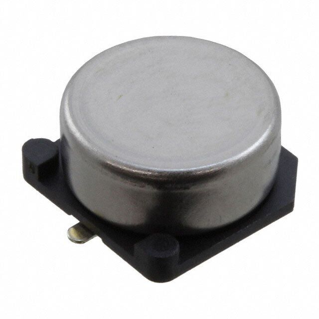
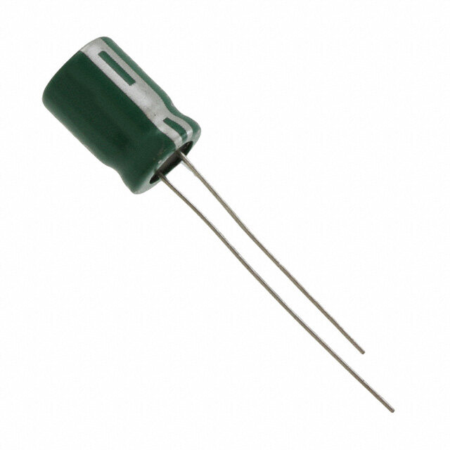
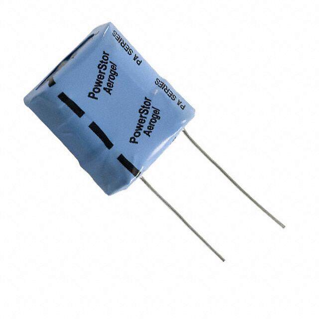
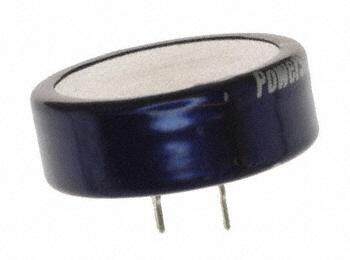
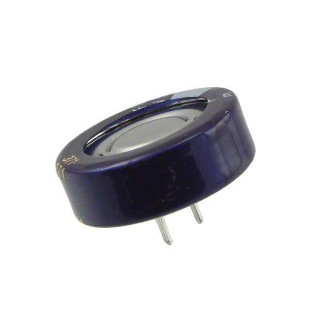
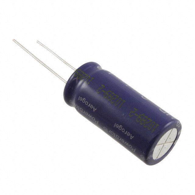
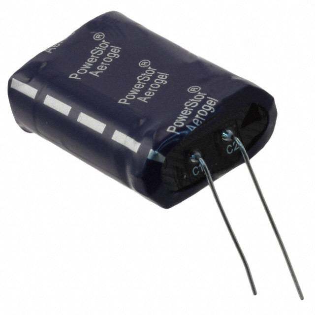
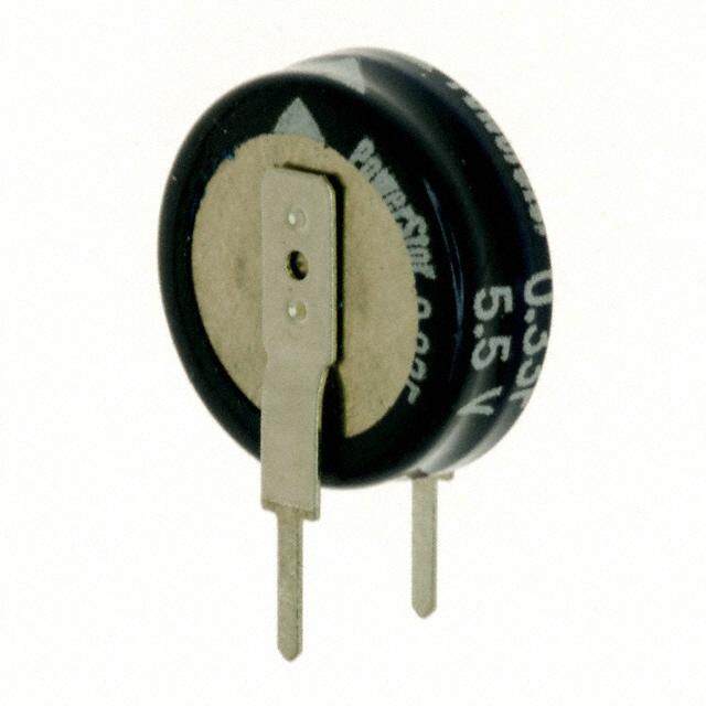
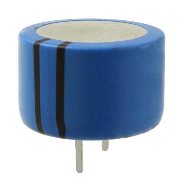
ICGOO电子元器件商城为您提供FCS0H104ZFTBR24由Kemet设计生产,在icgoo商城现货销售,并且可以通过原厂、代理商等渠道进行代购。 FCS0H104ZFTBR24价格参考。KemetFCS0H104ZFTBR24封装/规格:双电层电容器 (EDLC),超级电容器, 100mF (EDLC) Supercapacitor 5.5V Radial, Can - SMD 50 Ohm @ 1kHz 。您可以下载FCS0H104ZFTBR24参考资料、Datasheet数据手册功能说明书,资料中有FCS0H104ZFTBR24 详细功能的应用电路图电压和使用方法及教程。
| 参数 | 数值 |
| 产品目录 | |
| 描述 | CAP SUPER 0.1F 5.5V SMD VCHIP超级电容/超级电容器 0.1F 5.5volts SMD Super Capacitor |
| ESR | 100 Ohms |
| ESR(等效串联电阻) | 50 欧姆 |
| 产品分类 | |
| 品牌 | KemetKEMET NEC TOKIN |
| 产品手册 | http://www.kemet.com/docfinder?Partnumber=FCS0H104ZFTBR24 |
| 产品图片 |
|
| rohs | 符合RoHS无铅 / 符合限制有害物质指令(RoHS)规范要求 |
| 产品系列 | 超级电容/超级电容器,KEMET NEC TOKIN FCS0H104ZFTBR24FC |
| 数据手册 | http://www.kemet.com/docfinder?Partnumber=FCS0H104ZFTBR24 |
| 产品型号 | FCS0H104ZFTBR24FCS0H104ZFTBR24 |
| 不同温度时的使用寿命 | - |
| 产品 | Supercapacitors |
| 产品培训模块 | http://www.digikey.cn/PTM/IndividualPTM.page?site=cn&lang=zhs&ptm=30276 |
| 产品种类 | 超级电容/超级电容器 |
| 其它名称 | 399-10940-6 |
| 包装 | Digi-Reel® |
| 商标 | KEMET NEC TOKIN |
| 外壳宽度 | 10.8 mm |
| 外壳长度 | 10.8 mm |
| 外壳高度 | 5.5 mm |
| 大小/尺寸 | 0.421" 直径(10.70mm) |
| 安装类型 | 表面贴装 |
| 容差 | -20%,+80%- 20 %, + 80 % |
| 封装 | Reel |
| 封装/外壳 | 径向,Can - SMD |
| 工作温度 | -25°C ~ 70°C |
| 工作温度范围 | - 25 C to + 70 C |
| 工厂包装数量 | 1000 |
| 引线间距 | - |
| 标准包装 | 1 |
| 特色产品 | http://www.digikey.cn/product-highlights/cn/zh/kemet-super-capacitors/3964 |
| 电压-额定 | 5.5V |
| 电压额定值 | 5.5 V |
| 电压额定值DC | 5.5 V |
| 电容 | 0.1 Farad100mF |
| 端接类型 | SMD/SMT |
| 高度-安装(最大值) | 0.217"(5.50mm) |


- 商务部:美国ITC正式对集成电路等产品启动337调查
- 曝三星4nm工艺存在良率问题 高通将骁龙8 Gen1或转产台积电
- 太阳诱电将投资9.5亿元在常州建新厂生产MLCC 预计2023年完工
- 英特尔发布欧洲新工厂建设计划 深化IDM 2.0 战略
- 台积电先进制程称霸业界 有大客户加持明年业绩稳了
- 达到5530亿美元!SIA预计今年全球半导体销售额将创下新高
- 英特尔拟将自动驾驶子公司Mobileye上市 估值或超500亿美元
- 三星加码芯片和SET,合并消费电子和移动部门,撤换高东真等 CEO
- 三星电子宣布重大人事变动 还合并消费电子和移动部门
- 海关总署:前11个月进口集成电路产品价值2.52万亿元 增长14.8%


PDF Datasheet 数据手册内容提取
Supercapacitors FC Series Overview Applications FC Series Supercapacitors, also known as Electric Supercapacitors have characteristics ranging from Double-Layer Capacitors (EDLCs), are surface mount type traditional capacitors and batteries. As a result, components intended for high energy storage applications. supercapacitors can be used like a secondary battery The FC Series is designed specifically for reflow soldering, when applied in a DC circuit. These devices are best suited allowing them to be attached to a printed circuit board for use in low voltage DC hold-up applications such as (PCB) directly. embedded microprocessor systems with flash memory. Benefits • Surface mount without holder • Wide range of temperature from −25°C to +70°C • Maintenance free • Operational Voltage: 3.5 – 5.5 VDC • Highly reliable against liquid leakage • Lead-free and RoHS Compliant Part Number System FC 0H 104 Z F TB R 24 –SS Series Maximum Capacitance Capacitance Code (F) Environmental Tape Type Orientation Tape Width C-Spec Surface Mount Operating Voltage Tolerance FCS 0V = 3.5 VDC First two digits Z = −20/+80% F = Lead-free TB = R = Positive 24 = 24 mm –SS = 3 digit FC 0H = 5.5 VDC represent significant Embossed electrode 32 = 32 mm serial number figures. Third digit forward 44 = 44 mm marked on top specifies number of Blank = No serial zeros. number marking One world. One KEMET © KEMET Electronics Corporation • P.O. Box 5928 • Greenville, SC 29606 • 864-963-6300 • www.kemet.com S6011_FC • 3/29/2017 1
Supercapacitors – FC Series Dimensions – Millimeters B ±0.2 D ±0.5 A ±0.2 H Maximum Negative W ±0.1 L Terminal K Positive Terminal I P I Part Number D H A B I W P K L FC0H473ZFTBR24 10.5 5.5 10.8 10.8 3.6±0.5 1.2 5.0 0.7±0.3 0 (+0.3/−0.1) FC0H104ZFTBR24 10.5 5.5 10.8 10.8 3.6±0.5 1.2 5.0 0.7±0.3 0 (+0.3/−0.1) FC0H224ZFTBR24 10.5 8.5 10.8 10.8 3.6±0.5 1.2 5.0 0.7±0.3 0 (+0.3/−0.1) FC0H474ZFTBR32–SS 16.0 9.5 16.3 16.3 6.8±1.0 1.2 5.0 1.2±0.5 0 (+0.5/−0.1) FC0H105ZFTBR44–SS 21.0 10.5 21.6 21.6 7.0±1.0 1.4 10.0 1.2±0.5 0 (+0.5/−0.1) FC0V104ZFTBR24 10.5 5.5 10.8 10.8 3.6±0.5 1.2 5.0 0.7±0.3 0 (+0.3/−0.1) FC0V224ZFTBR24 10.5 5.5 10.8 10.8 3.6±0.5 1.2 5.0 0.7±0.3 0 (+0.3/−0.1) FC0V474ZFTBR24 10.5 8.5 10.8 10.8 3.6±0.5 1.2 5.0 0.7±0.3 0 (+0.3/−0.1) FCS0H473ZFTBR24 10.7 5.5 10.8 10.8 3.9±0.5 1.2 5.0 0.9±0.3 0 (+0.3/−0.1) FCS0H104ZFTBR24 10.7 5.5 10.8 10.8 3.9±0.5 1.2 5.0 0.9±0.3 0 (+0.3/−0.1) FCS0H224ZFTBR24 10.7 8.5 10.8 10.8 3.9±0.5 1.2 5.0 0.9±0.3 0 (+0.3/−0.1) FCS0V104ZFTBR24 10.7 5.5 10.8 10.8 3.9±0.5 1.2 5.0 0.9±0.3 0 (+0.3/−0.1) FCS0V224ZFTBR24 10.7 5.5 10.8 10.8 3.9±0.5 1.2 5.0 0.9±0.3 0 (+0.3/−0.1) FCS0V474ZFTBR24 10.7 8.5 10.8 10.8 3.9±0.5 1.2 5.0 0.9±0.3 0 (+0.3/−0.1) © KEMET Electronics Corporation • P.O. Box 5928 • Greenville, SC 29606 • 864-963-6300 • www.kemet.com S6011_FC • 3/29/2017 2
Supercapacitors – FC Series Performance Characteristics Supercapacitors should not be used for applications such as ripple absorption because of their high internal resistance (several hundred mΩ to a hundred Ω) compared to aluminum electrolytic capacitors. Thus, its main use would be similar to that of secondary battery such as power back-up in DC circuit. The following list shows the characteristics of supercapacitors as compared to aluminum electrolytic capacitors for power back-up and secondary batteries. Secondary Battery Capacitor NiCd Lithium Ion Aluminum Electrolytic Supercapacitor Back-up ability – – – – Eco-hazard Cd – – – Operating Temperature Range −20 to +60°C −20 to +50°C −55 to +105°C −40 to +85°C (FR, FT) Charge Time few hours few hours few seconds few seconds approximately 500 to 1,000 Charge/Discharge Life Time approximately 500 times limitless (*1) limitless (*1) times Restrictions on yes yes none none Charge/Discharge Flow Soldering not applicable not applicable applicable applicable applicable Automatic Mounting not applicable not applicable applicable (FM and FC series) leakage, combustion, Safety Risks leakage, explosion heat-up, explosion gas emission (*2) explosion, ignition (*1) Aluminum electrolytic capacitors and supercapacitors have limited lifetime. However, when used under proper conditions, both can operate within a predetermined lifetime. (*2) There is no harm as it is a mere leak of water vapor which transitioned from water contained in the electrolyte (diluted sulfuric acid). However, application of abnormal voltage surge exceeding maximum operating voltage may result in leakage and explosion. Typical Applications Intended Use (Guideline) Power Supply (Guideline) Application Examples of Equipment Series CMOS microcomputer, CMOS microcomputer, Long time back-up 500 μA and below static RAM/DTS FC series IC for clocks (digital tuning system) Environmental Compliance All KEMET supercapacitors are RoHS Compliant. RoHS Compliant © KEMET Electronics Corporation • P.O. Box 5928 • Greenville, SC 29606 • 864-963-6300 • www.kemet.com S6011_FC • 3/29/2017 3
Supercapacitors – FC Series Table 1 – Ratings & Part Number Reference Nominal Maximum Maximum Voltage Holding Capacitance Maximum ESR Part Number Operating Current at 30 Characteristic Weight (g) Discharge at 1 kHz (Ω) Voltage (VDC) Minutes (mA) Minimum (V) System (F) FC0V104ZFTBR24 3.5 0.10 50 0.09 — 1.0 FCS0V104ZFTBR24 3.5 0.10 100 0.09 — 1.0 FC0V224ZFTBR24 3.5 0.22 25 0.20 — 1.0 FCS0V224ZFTBR24 3.5 0.22 50 0.20 — 1.0 FC0V474ZFTBR24 3.5 0.47 25 0.42 — 1.4 FCS0V474ZFTBR24 3.5 0.47 50 0.42 — 1.4 FC0H473ZFTBR24 5.5 0.047 50 0.071 4.2 1.0 FCS0H473ZFTBR24 5.5 0.047 100 0.071 4.2 1.0 FC0H104ZFTBR24 5.5 0.10 25 0.15 4.2 1.0 FCS0H104ZFTBR24 5.5 0.10 50 0.15 4.2 1.0 FC0H224ZFTBR24 5.5 0.22 25 0.33 4.2 1.4 FCS0H224ZFTBR24 5.5 0.22 50 0.33 4.2 1.4 FC0H474ZFTBR32–SS 5.5 0.47 13 0.71 4.2 4.0 FC0H105ZFTBR44–SS 5.5 1.0 7 1.50 4.2 6.7 Part numbers in bold type represent popularly purchased components. Land Pattern C Logo B A B Land Pattern Lead Terminal Diameter (mm) A B C A B C 10.5 5.0 4.6 2.5 5.0 3.6 1.2 10.7 5.0 4.9 2.5 5.0 3.9 1.2 16 5.0 10.0 2.5 5.0 6.8 1.2 21 10.0 10.5 3.5 10.0 7.0 1.4 © KEMET Electronics Corporation • P.O. Box 5928 • Greenville, SC 29606 • 864-963-6300 • www.kemet.com S6011_FC • 3/29/2017 4
Supercapacitors – FC Series Precautions for Use • This series is exclusively for reflow soldering. It is designed for thermal conduction system such as combination use of infrared ray and heat blow. Consult with KEMET before applying other methods. • The reflow condition must be kept within reflow profile graphs shown below. • Applying reflow soldering is limited to 2 times. After the first reflow, cool down the capacitor thoroughly to 5 – 35°C before the second reflow. Always consult with KEMET when applying reflow soldering in a more severe condition than the condition described here. FCS Type FC Type Reflow Profile Temperature on the Reflow Profile Capacitor Top 300 Peak temperature Peak Temperature: 235°C, within 10 seconds 260°C 250 250 Temperature (°C) 112050000 125000°°CC se1co5n0ds217°C sec7o0n ds mperature on thepacitor Top (°C) 211050000 160°C 120 s econds 50 TeCa 50 0 Tp Time exceeding 200°C 0 50 100 150 200 250 300 350 400 0 Time (seconds) Time ( seconds) Above "Reflow Profile" graph indicates temperature at the terminals and Above "Reflow Profile" graph indicates temperature at the terminals capacitor top. and capacitor top. Peak Temperature Below +260°C Over +255°C Within 10 seconds Over +230°C Within 45 seconds Tp Time Exceeding 200°C Over +220°C Within 60 seconds 250 C) Over +217°C Within 70 seconds e (° 240 ur Time between +150°C to 150 seconds at 230 +200°C (temperature zone per m 220 over +170°C within 50 Te seconds) ak 210 e P 200 0 10 20 30 40 50 60 Tp (seconds) © KEMET Electronics Corporation • P.O. Box 5928 • Greenville, SC 29606 • 864-963-6300 • www.kemet.com S6011_FC • 3/29/2017 5
Supercapacitors – FC Series Specifications Test Conditions Item FC 5.5 V Type, 3.5 V Type (conforming to JIS C 5160-1) Category Temperature Range −25°C to +70°C Maximum Operating Voltage 5.5 VDC, 3.5 VDC Capacitance Refer to Table 1 Refer to “Measurement Conditions” Capacitance Allowance +80%, −20% Refer to “Measurement Conditions” Measured at 1 kHz, 10 mA; See also ESR Refer to Table 1 “Measurement Conditions” Current (30 minutes value) Refer to Table 1 Refer to “Measurement Conditions” Surge voltage: 4.0 V (3.5 V type,3.6 Capacitance > 90% of initial ratings V type) Charge: 6.3 V (5.5 V type) Discharge: 30 seconds Number of cycles: 9 minutes 30 seconds ESR ≤ 120% of initial ratings Series resistance: 1,000 0.043 F, 0.047 F 300 Ω * Surge 0.068 F 240 Ω 0.10 F 150 Ω Current (30 minutes value) ≤ 120% of initial ratings 0.22 F 56 Ω 0.47 F 30 Ω 1.0 F 15 Ω Discharge Appearance No obvious abnormality resistance: 0 Ω Temperature: 70±2°C Capacitance ≥ 50% of initial value Conforms to 4.17 Phase 2 Phase 1: +25±2°C ESR ≤ 400% of initial value Phase 2: −25±2°C Capacitance Phase 4: +25±2°C Phase 3 ESR Phase 5: +70±2°C Phase 6: +25±2°C * Characteristics in Capacitance ≤ 200% of initial value Different Temperature ESR Phase 5 Satisfy initial ratings Current (30 minutes value) 1.5 CV (mA) or below Capacitance Within ±20% of initial value ESR Phase 6 Satisfy initial ratings Current (30 minutes value) Satisfy initial ratings Capacitance Conforms to 4.13 Frequency: 10 to 55 Hz ESR Satisfy initial ratings * Vibration Resistance Testing Time: 6 hours Current (30 minutes value) Appearance No obvious abnormality Capacitance Cooled down to ambient temperature after ESR Satisfy initial ratings reflow soldering, then the product must * Solder Heat Resistance Current (30 minutes value) fulfill the condition stated left. (See Precautions for Use) Appearance No obvious abnormality Capacitance Conforms to 4.12 Temperature ESR Satisfy initial ratings Condition: −25°C » Room * Temperature Cycle temperature » Current (30 minutes value) +70°C » Room temperature Appearance No obvious abnormality Number of cycles: 5 cycles * Must fulfill the above condition after reflow soldering. © KEMET Electronics Corporation • P.O. Box 5928 • Greenville, SC 29606 • 864-963-6300 • www.kemet.com S6011_FC • 3/29/2017 6
Supercapacitors – FC Series Specifications cont’d Test Conditions Item FC 5.5 V Type, 3.5 V Type (conforming to JIS C 5160-1) Capacitance Within ±20% of initial value Conforms to 4.14 Temperature: +40±2°C * High Temperature and ESR ≤ 120% of initial ratings Relative humidity: 90 to 95% RH High Humidity Resistance Current (30 minutes value) ≤ 120% of initial ratings Testing time: 240±8 hours Appearance No obvious abnormality Capacitance Within ±30% of initial value Conforms to 4.15 Voltage applied: Maximum operating ESR < 200% of initial ratings voltage * High Temperature Load Series protection Current (30 minutes value) < 200% of initial ratings resistance: 0 Ω Testing time: 1,000+48 (+48/−0) Appearance No obvious abnormality hours Charging condition Voltage applied: 5.0 VDC (Terminal at Voltage between terminal leads the case side must be 5.5 V type: > 4.2 V negative) Series resistance: 0 Ω * Self Discharge Characteristics Charging time: 24 hours (Voltage Holding Characteristics) Storage Let stand for 24 hours in condition described below with terminals opened. 3.5 V type: Not specified Ambient < 25°C temperature: < 70% RH Relative humidity: * Must fulfill the above condition after reflow soldering. Marking D = 10.5 mm D = 16 & 21 mm D = 10.7 mm Polarity Nominal Series Name Logo Polarity Nominal (negative) (negative) Capacitance Capacitance Maximum Maximum N T Operating Voltage Maximum Polarity 473 Operating Voltage FC 5.5V 473 Operating Voltage (negative) 5.5V 474 Nominal 5.5V A1 A1-001 Capacitance A1 S FCS Type Date Code Serial Number Date Code Date Code Displays nominal capacitance, maximum operating voltage serial number, polarity, etc. © KEMET Electronics Corporation • P.O. Box 5928 • Greenville, SC 29606 • 864-963-6300 • www.kemet.com S6011_FC • 3/29/2017 7
Supercapacitors – FC Series Tape & Reel Packaging Information – Millimeters E C B D R:10 t A W Mark TBR24 TBR32 TBR44 A 380±2 330±2 380±2 Product height 5.5 mm 80±1 B 100±1 100±1 Product height 8.5 mm 100±1 C 13±0.5 13±0.5 13±0.5 D 21±0.8 21±0.8 21±0.8 E 2±0.5 2±0.5 2±0.5 Product height 5.5 mm 25.5±0.5 W 33.5±1.0 45.5±1.0 Product height 8.5 mm 25.5±1.0 t 2.0 2.0 2.0 © KEMET Electronics Corporation • P.O. Box 5928 • Greenville, SC 29606 • 864-963-6300 • www.kemet.com S6011_FC • 3/29/2017 8
Supercapacitors – FC Series Tape & Reel Packaging Information – Millimeters cont'd ø D t1 Sprocket holeP P ø D0 t1 P2 P0 0 2 0 E E A A F F W G B W B t Ifnodr efinttteindg s squupaerre -chaoplaecitors P1 Forward direction t2 Super capacitors fitting P1 2 Super capacitors fitting on square-hole R0.75 0.2 on square-hole Mark TBR24 TBR32 TBR44 W 24.0 32.0 44.0 A 11.4 18.0 23.0 B 13.0 20.0 25.0 P 4.0 4.0 4.0 0 P 16.0 24.0 32.0 1 P 2.0 2.0 2.0 2 F 11.5 14.2 20.2 ø D 1.55 1.55 1.55 0 t 0.4 0.5 0.5 1 E 1.75 1.75 1.75 Product height 5.5 mm 6.0 t 10.0 12.0 2 Product height 8.5 mm 8.4 G – 28.4 40.4 Ammo Pack Packaging Information Part Number Quantity per Reel FC0H473ZFTBR24 1,000 pieces/reel FC0H104ZFTBR24 1,000 pieces/reel FC0H224ZFTBR24 500 pieces/reel FC0H474ZFTBR32–SS 200 pieces/reel FC0H105ZFTBR44–SS 150 pieces/reel FC0V104ZFTBR24 1,000 pieces/reel FC0V224ZFTBR24 1,000 pieces/reel FC0V474ZFTBR24 500 pieces/reel FCS0H473ZFTBR24 1,000 pieces/reel FCS0H104ZFTBR24 1,000 pieces/reel FCS0H224ZFTBR24 500 pieces/reel FCS0V104ZFTBR24 1,000 pieces/reel FCS0V224ZFTBR24 1,000 pieces/reel FCS0V474ZFTBR24 500 pieces/reel © KEMET Electronics Corporation • P.O. Box 5928 • Greenville, SC 29606 • 864-963-6300 • www.kemet.com S6011_FC • 3/29/2017 9
Supercapacitors – FC Series List of Plating & Sleeve Type By changing the solder plating from leaded solder to lead-free solder and the outer tube material of can-cased conventional supercapacitor from polyvinyl chloride to polyethylene terephthalate (PET), our supercapacitor is now even friendlier to the environment. a. Iron + copper base + lead-free solder plating (Sn-1Cu) b. SUS nickel base + copper base + reflow lead-free solder plating (100% Sn, reflow processed) Series Part Number Plating Sleeve FC0H473ZFTBR24 b No tube used FC0H104ZFTBR24 b No tube used FC0H224ZFTBR24 b No tube used FC0H474ZFTBR32–SS a No tube used FC0H105ZFTBR44–SS a No tube used FC0V104ZFTBR24 b No tube used FC0V224ZFTBR24 b No tube used FC FC0V474ZFTBR24 b No tube used FCS0H473ZFTBR24 b No tube used FCS0H104ZFTBR24 b No tube used FCS0H224ZFTBR24 b No tube used FCS0V104ZFTBR24 b No tube used FCS0V224ZFTBR24 b No tube used FCS0V474ZFTBR24 b No tube used Recommended Pb-free solder : Sn/3.5Ag/0.75Cu Sn/3.0Ag/0.5Cu Sn/0.7Cu Sn/2.5Ag/1.0Bi/0.5Cu © KEMET Electronics Corporation • P.O. Box 5928 • Greenville, SC 29606 • 864-963-6300 • www.kemet.com S6011_FC • 3/29/2017 10
Supercapacitors – FC Series Measurement Conditions Capacitance (Charge System) Capacitance is calculated from expression (9) by measuring the charge time constant (τ) of the capacitor (C). Prior to measurement, the capacitor is discharged by shorting both pins of the device for at least 30 minutes. In addition, use the polarity indicator on the device to determine correct orientation of capacitor for charging. Capacitance: τ Eo: 3.0 (V) Product with maximum operating voltage of 3.5 V (F) (9) C = Rc 5.0 (V) Product with maximum operating voltage of 5.5 V 6.0 (V) Product with maximum operating voltage of 6.5 V Switch 10.0 (V) Product with maximum operating voltage of 11 V 12.0 (V) Product with maximum operating voltage of 12 V Rc τ: Time from start of charging until Vc becomes 0.632 Eo (V) + Eo C Vc (seconds) – Rc: See table below (Ω). Charge Resistor Selection Guide FY FM, FME FG Cap FA FE FS FR FMC FGH FT FC, FCS HV FYD FYH FYL FMR, FML FGR 0.010 F – – – – – 5,000 Ω – 5,000 Ω – 5,000 Ω – – – – 0.022 F 1,000 Ω – 1,000 Ω2,000 Ω2,000 Ω2,000 Ω2,000 Ω 2,000 Ω – 2,000 Ω – – Discharge – 0.033 F – – – – – – – Discharge – – – – – – 0.047 F 1,000 Ω1,000 Ω1,000 Ω2,000 Ω1,000 Ω2,000 Ω1,000 Ω 2000 Ω 1,000 Ω 2,000 Ω – – – – 0.10 F 510 Ω 510 Ω 510 Ω 1,000 Ω 510 Ω – 1,000 Ω 1000 Ω 1,000 Ω 1,000 Ω Discharge 510 Ω Discharge – 0H: Discharge 0.22 F 200 Ω 200 Ω 200 Ω 510 Ω 510 Ω – 510 Ω – 1,000 Ω Discharge 200 Ω Discharge – 0V: 1000 Ω 0.33 F – – – – – – – – Discharge – – – – – 0.47 F 100 Ω 100 Ω 100 Ω 200 Ω 200 Ω – 200 Ω – – 1,000 Ω Discharge 100 Ω Discharge – 1.0 F 51 Ω 51 Ω 100 Ω 100 Ω 100 Ω – 100 Ω – – 510 Ω Discharge 100 Ω Discharge Discharge 1.4 F – – – 200 Ω – – – – – – – – – – 1.5 F – 51 Ω – – – – – – – 510 Ω – – – – 2.2 F – – – 100 Ω – – – – – 200 Ω – 51 Ω – – 2.7 F – – – – – – – – – – – – – Discharge 3.3 F – – – – – – – – – – – 51 Ω – – 4.7 F – – – – – – – – – 100 Ω – – – Discharge 5.0 F – – 100 Ω – – – – – – – – – – – 5.6 F – – – – – – – – – – – 20 Ω – – 10.0 F – – – – – – – – – – – – – Discharge 22.0 F – – – – – – – – – – – – – Discharge 50.0 F – – – – – – – – – – – – – Discharge 100.0 F – – – – – – – – – – – – – Discharge 200.0 F – – – – – – – – – – – – – Discharge *Capacitance values according to the constant current discharge method. *HV Series capacitance is measured by discharge system © KEMET Electronics Corporation • P.O. Box 5928 • Greenville, SC 29606 • 864-963-6300 • www.kemet.com S6011_FC • 3/29/2017 11
9. Measurement Conditions (1) Capacitance ( Charge System ) Capacitance is calculated from expression (9) by measuring the charge time constant (τ) of the capacitor (C). Prior to measurement, short between both pins of the capacitor for 30 minutes or more to let it discharge. In addition, follow the indication of the product when determining the polarity of the capacitor during charging. τ Capacitance: C = (F) (9) EO: 3.0 (V) … Product with maximum operating voltage RC 3.5 V 5.0 (V) … Product with maximum operating voltage 5.5 V 6.0 (V) … Product with maximum operating voltage Swich 6.5 V 10.0 (V) … Product with maximum operating voltage RC + EO C VC 11 V – 12.0 (V) … Product with maximum operating voltage 12 V τ: Time from start of charging until Vc becomes 0.632E0 (V) (sec) RC: See table below (Ω). FY FM, FME FG FC, FA FE FS FR FMC FGH FT FYD FYH FYL FMR, FML FGR FCS 0.010F – – – – – 5000 Ω – 5000 Ω – 5000 Ω – – – 0.022F 1000 Ω – 1000 Ω 2000 Ω 2000 Ω 2000 Ω 2000 Ω 2000 Ω – 2000 Ω – – Discharge 0.033F – – – – – – – Discharge – – – – – 0.047F 1000 Ω 1000 Ω 1000 Ω 2000 Ω 1000 Ω 2000 Ω 1000 Ω 2000 Ω 1000 Ω 2000 Ω – – – 0.10F 510 Ω 510 Ω 510 Ω 1000 Ω 510 Ω – 1000 Ω 1000 Ω 1000 Ω 1000 Ω Discharge 510 Ω Discharge 0H: Discharge 0.22F 200 Ω 200 Ω 200 Ω 510 Ω 510 Ω – 510 Ω – 1000 Ω Discharge 200 Ω Discharge 0V: 1000 Ω 0.33F – – – – – – – – Discharge – – – – 0.47F 100 Ω 100 Ω 100 Ω 200 Ω 200 Ω – 200 Ω – – 1000 Ω Discharge 100 Ω Discharge 1.0F 51 Ω 51 Ω 100 Ω 100 Ω 100 Ω – 100 Ω – – 510 Ω Discharge 100 Ω Discharge 1.4F – – – 200 Ω – – – – – – – – – 1.5F – 51 Ω – – – – – – – 510 Ω – – – 2.2F – – – 100 Ω – – – – – 200 Ω – 51 Ω – 3.3F – – – – – – – – – – – 51 Ω – 4.7F – – – – – – – – – 100 Ω – – – 5.0F – – 100 Ω – – – – – – – – – – 5.6F – – – – – – – – – – – 20 Ω – Sup*eCrcaappaacciittaonrsc e– FvCa luSeersie asccording to the constant current discharge method. *HV series capacitance is measured by discharge system. Measurement Conditions cont’d Table 3 Capacitance measurement CapCaaciptaancciet a(Dniscceh a(rDgies Scyhsatermg)e System) As shown in the diagram below, charging is performed for a duration of 30 minutes once the voltage of the capacitor In Cthae pdaiacgriatman bceleo w(,D cihsacrghinag rigs epe Srfoyrmsteed mfor: 3a. 5duVra)tion of 30 minutes, once the voltage of the condensor terminal terminal reaches 5.5 V. Then, use a constant current load device and measure the time for the terminal voltage to drop reaches 5.5 V. In the diagram below, charging is performed for a duration of 30 minutes, once the voltage of the capacitor terminal reaches 3.5V. from 3.0 to 2.5 V upon discharge at 0.22 mA per 0.22 F, for example, and calculate the static capacitance according to the Then, use a constant current load device and measure the time for the terminal voltage to drop from 3.0 to 2.5 V upon Then, use a constant current load device and measure the time for the terminal voltage to drop from 1.8 to 1.5V upon equation shown below. discharge at 0.22 mA for 0.22 F, for example, and calculate the static capacitance according to the equation shown below. discharge at 1 mA per 1F, and calculate the static capacitance according to the equation shown below. Note: The current value is 1 mA discharged per 1 F. Note: The current value is 1 mA discharged per 1F. (V) 0.22mA(I) SW SW A A 3.5V 5.5V V1 : 1.8V V1 : 3.0V CaCpa=ct a In × c V e( 1T : - 2 -C V = T2 1 ) I × V ( (1T F - 2) - V T2 1 ) 3(.F5)V 5.5VV C V C R R VV12 VoltageVV12 V2 : 1.5V V1 : 2.5V 30T m1in. T2 T1Time T(s2ec.)Duration (sec.) 30 minutes Capacitance (Discharge System – 3.5 V) As 3s6h o wSnuCC pinaae ptprh aCae ccadCpiiiattaaaagcprnniatacocmcree sbi t e((VaDDloonwlii.css1, ecc3ch hh(aDaargrriigsgngcee h isSSa pyyresgsrftteoee rmSmmye::dHs3 ft.Vo5ersVm ae) :dr3uie.r5astVi)o)n of 30 minutes once the voltage of the capacitor terminal rCeaacpIhnea tschC e3it .ad5aip aVnga.c rTcaehmi te( anbD,ne uilocssweec, hac( hDacaorirnsggsicentagh Sn iasty rcpgsuerterrfeoe Smrnmty :elos3dat .fd5eo Vrmd ae) :vd3icu.er5a atVino)nd omf e3a0s murien uthtees ,t iomnec efo thr eth veo tlteargmei noaf lt hveo lctaapgaec tioto dr rteorpm firnoaml r eaches In the diaIng rtahme dbiealgorwa,m c hbaerlogwin,g c ihsa prgeirnfogr mis epde rfoforr am deudr faotrio an douf r3a0ti omni nouf t3e0s ,m oinncuete tsh,e o vnocleta tghee ovfo tlhtaeg cea opfa tchieto cr atepramciintoarl treeramcihneasl r3e.a5cVh.es 3.5V. 1.8 to 1.5 V upMTInoh atnehx n.ed , oi dspuicaeTIsnhgerh aart eahtarinmgen , ceg dbou iaveansotlgseo l1rtt waaa.a0,mng c ctem hbo.caenAurlso rgprtwiaene,nng rc tt 1 i hscl.ao 0upra rgeFdrir,en ffondgorte mi rsv loe eipcaxdeead rf m ofaodrnrp eamdlv e deimc,ud ear efa noaatdrisno aucdn ra deomlucf rteu3aha0lteais o mtutneirim neotuhf e tte3 hef 0seos , rtm taoitimnthnicecuee t ce tftesaohr,pre m oa tvnhicnoceialtet aal t tegnvhrecoem el otvi afnao gtalchtealce gov tceoora d lotpdiafnar gtogchepi ett o o tfcror aott ehpdmrearmo ce1piintq.o 8afurr l a ottroetemir aom1 cn1.ih5n .e8Vas l t uro3ep .a51ocV.nh5. eVs u3p.5oVn. shown below.TdTihhseecnnh,,a urugsdTseeeih s aa eca tnhc 1,aoc rnoumgsnseAtsea ta npaatten 1crct u1omcrFnruAe,sr n ratpaetn ennldortt a 1ccldoaFu a,ldrc draeue nvlndadictet eecvl oaitachalnceedud a lsdamtnetaedevt ia ictmchs ecuee ar aeasps tnaatuhdctrei icetm a t cintemhacapeees a uftacoirmciret cat ehont hercfdeo eti ren tarigtmmch cteieono atrtfedhol rievrnm o gtelhit nqateoaug laet tehtv itreooom nl etdi anqsrgoahuepola wtvftirooono nl mtdb asr ego2hleop.o0 w w tfot.rnoo dmb1re.o 5l1opV.w 8fu.r potoom n1 1d.5.is8Vc htuoap r1og.ne5 V upon adti s1c hmaArg pdeeis rac 1th F1a, rmagneAd a pcte a1rl c 1muFlAa, t aepn etdhr e1c aFs,tlca autinclad ct eac apthalcecui tlsaatntaect iecth aceca cspotaarcdtiicitna gcna ctope a tahcceitc aeonqrcudeain taigoc ncto os rthdhoienw gen q tboue atlhotieow n.e qshuoawtionn b sehlooww.n below. (V) (V) CCC=== III ××× VVV CC((( 111T TT ---== 222 --- VVV II T TT222 ×× 111 VV))) (( 11TT -- 22 (((-- FFFVV ))) TT22 11 )) ((FF))333...555VVV 33..55VVVVV SSSWWWCCCVV AAASSWWCC RRRAA RR333...((555VVVVVVVVVVV121212)) 33..(55VVVVVVV1212) VVVVVV212121 :::::: 121111......505858VVVVVV VVVV2121 :::: 1111....5858VVVV T1 T2 TT1ime (Tse2c.) Time (sec.) 30 minutes30 mTTi11nutesTT22 TTT1iimmee ((Tssee2cc..)) Time (sec.) 3300 mmiinnuutteess30 minutes CapacCitaapnaccei t(aDnicsec h(Darisgceh Sayrgstee Smy:sHtVesme:rHieVss)eries) Capacitance (Discharge System – HV Series) ECqaupiavcCailtaeapnnatc cseie t(arDineicssec r h(eDasriisgscetah Snaycrgset e(e ESmSy:RsHt)Vesme:rHieVss)eries) As shown in tIhne t hdeia dgiIranag mtrha emb ed blioaewglor,aw cm,h c abhreaglriognwign, gics hi spa eprgrefirnofgorm rimse epdde f rfofoorrr ama dedudu rrfaaottrii ooann d oouffr a33t00io mnm ioninfu u3tet0es s,m ooinnnuccetee tsth,h eoe nv vocoeltla ttaghgeee ov oof fltth atehg eec acopaf apthcaietco icrta otper armciitnoar lt erermacinhaels r eaches terminal reacEMIhneSa tsRxh .me so dhapiaxMIeanlirglm a abtrxhtauei.nemm ocg d ap bovileaecoprgullaeotrlatarawiagnmt,et egci d.n bhv gefaor lorlvotgmaowignl ,tt egahc. gheisae epr. qgeTuirnhafgoet irnoims,n eup bdsee erffl oooarwr mca.o edndus rftaoatrni oatn cd ouufrr ra3et0ino mtn l ioonafu d3te 0ds ,em voiinncuceet ea tsnh, edo nvmoceeltaa tsghueer eov oft lththaeeg tecim aopef a tfhcoietro ctrha tepe armciitnoar lt erermacinhaels r eaches terminal voltaTMghaeex nt.o ,o udpsrTMeeorh apaaext nif.cnr ,oo ogunp msvseeot ra2 laatn.at0 ticgn coteguon. rv sr1oet.al5ntnat tVg loc euau.pdrr oednnet v dlioicsaecd ah dnaedrgv miec eea atas n1ud.r0e m mtheAea s tpuimerere 1tfho.0er Ftthi,m eae nt edfor mrc atinhlaecl u tvelaormtlteai ngtahel e tv oso tdltaarotgipce fctrooa mpdar o2cp.i0t f artoonm c1e .52 aV.0c cutoop or1dn.5i ndVgis ucphoanrg dei scharge to the equatioaTnth 1es nhm,o Auw spaTneeth Vbr1ae eC 1nmclF,oo ,Au nwa sspn.etead ran c 1tca Fcol,cu naursrnlaetadtnen tc tat lhoclceauu drsrl aetdatneettiv ctlih occ1eaea0 d pmsa tadAnacedtiivtc ami ccneeac apeasa naucdcrite cam ontrhecdeaein s taguimc rtecoe o ttfrhhodeerin tteghimq etuoe ta etfthoriomer n tien hsqaehul otavewtoriomnltna bin gseaehlol otvwowo .dnltar bogepel o ftrwoo .mdr o2p.0 f rtoom 1 .52V.0 utop o1n.5 dVis ucphoanrg dei scharge aEtS 1R m=A pa 0et r.1 0 1 m1 F ,A a( Ωpned)r c1aFl,c aunladte c atfh:l1ceku Hslaztateti cth cea pstaaCctiitca cnacpea accitcaonrcdeVin Cagc tcoo trhdein egq tuoa t(thVio)en e sqhuoaw(tVion)n b sehlooww.n below. SSWW ASSWW A 3.(5VV) 3.(5VV) V1 : 2.0V V1 : 2.0V CurCCCru==errn e IItn ×× t (VV sCC((a 11TT h --==t 22a -- l3VV l bII TT220 ×× e 11 VV)) m(( c 11TT a -- 22 il ((--c nFFVV u ))u TT22l a 11t t)) ee d s ((f FFrao))33mf..55t VVethre ceqh33..u55aaVVrtVVigonin bgelCCo)VVw. A CC RRA RR 3.5VVVVV1212 3.5VVVVV1212 VVV221 ::: 112...550VVV VVV221 ::: 112...550VVV Prior to measurement, both lead terminals must be short-circuited for a minimum of 30T 1minTu2tesTT1.ime (Tse2c.) Time (sec.) The lead terminal connected to the metal can case is connected to the nega3t0i vmein usteidse30 omTfi1 ntuhteesT 2powTT1iemre (sTse2ucp.)pTliym.e (sec.) 30 minutes30 minutes EquivEalqeunitv saelerniets s reersieisst raenscies t(aEnScRe )(ESR) EquEiov:Ea 2lq.e5uVnidtvc sa (HeleVrniseetsr ise rsee r5si0eFiss)t raenscies t(aEnScRe )(ESR) ESR shaEllS bRe schaalcllu blaet ecda lfcruolmat ethde f reoqmu athtieo ne qbuealotwio.n below. ESR 2s.h7aEVllSd bcRe ( sHchaValsclleu brlaieet esc dae lxfcrcuoelmapt tet h5de0 f Freo)qmu athtieo ne qbuealotwio.n below.VR SW 3.0Vdc (3.5V type) R EEcSS:RR ==1510.00 00 VEE 0Ω 00 dSSΩVV .. c 00RR CC( 110( ==( 5.0 1 .. ((500 ΩΩ VF1 00 , 0VV )).. t 000yF CC 11p., 2 e0 2 ).((F0ΩΩ,2 02)).F4,ff7 ::011Fkk.0HH)4zz7F)ff::1111kk00HHmmzzAACC 11E00OmmAACC VVRCCC VVCC C+- 10Ω (1.0F, 1.5F, 2.2F, 4.7F) 2.2Ω (HVseries) CurreCntu (raret n3t0 (mati n3u0 tmesin auftteers cahftaerrg cinhga)rging) © KEMET ElCecutrornrices CnCotur p(roarraetti on3nV t0•R P (.mOa. tBi on3x u059 t2me8 s•i Gn areuefnttveeillrse , cSaCh f2ta9e6r0rg6 ci• n8h6g4a-)9r6g3-i6n30g0) • www.kemet.com S6011_FC • 3/29/2017 12 CCuurrrreenntt =Cshu ar r ll e b n e t sc h a(aAlcl)lu blaet ecda lfcruolmat ethde f reoqmu athtieo ne qbuealotwio.n below. PCruiorrre tnot mPCshrueiaorarlrsleR tubnoCret e m scmhaeaelaclnslu tub,l arebet oecmtdahe l fcnlreuot,alm abdt oe tthtdehe r fm lreeoiqanmuda a lttshtei eomrm neu iqbsnueta alblostewi om s.nhu bosetr tlb-ocewi rs.chuoitretd-c firocru ait emdi nfoimr uam m oinfi m30u mm ionfu 3te0s .minutes. TPhrieo rl etoa dmTP htreeieoar rmsl etuioanr edamm lt eeceaornmsntu,ni nrbeeaocmlt techeod nlne tt,nao bed toc httteeehr d mmle teiaontd aat hllts eec mar mmnu eiscnttaaa bslls eec ma issnhu coscotar tnbs-cneeie risccshut ecoitodretn d-tcno fie rotcchrut eeai td nem edtoig nf aoitmhtri evuae m nm se oiigdnfaei m3t io0vufe m mt hs ioinedfu e p3t eoo0swf .methrine su uptpeopsw.ley.r supply. Self-discharge characteristic (0H: 5.5V products) The leadT hteer mleianda lt ecormnnineaclt ecodn tnoe tchtee dm teot athl eca mn ectaasl ec aisn ccoansnee icst ecodn tnoe tchtee dn etog athtieve n seigdaet iovfe t hsied ep oowf ethre s uppopwley.r supply. TEhoe: s2e.l5f-EVdodis:cc (h2Ha.5VrgVsede crci eh(Hsa rV5a0sceFter)ireisst i5c 0isF )measured by charging a voltage of 5.0 Vdc (charge protection resistance: 0Ω) according t Eoo t:he 22 c..57a EVVpodda:ccc i ((t22oHH..r57VV pVVssoddeelccrraii eer((iHHssty VV5e f0xossceeFr err)2iipee4tss h5 5eo00xuFcFr)es),p tth 5e0nF r)eleasing betweVeRn the VpRins fSoWr 24 hoSuWrs and measuring the pin-to-pin voltage. T he t32e..s07t VVsddhcco u((323Hld...07V5 bVVsVedde tccrcyi eap((3Hsrer .)iVe5exsVdce oteryiupepttse i5 n)e0 xaFcn)e epnt v5i0roFn)ment with an aVmR bient VtRempSeWrature SoWf 25℃ or below and relative humidity of 70% R H o53r ..b00e VVloddwcc .((5353....0055VVVVdd ttccyy pp((53ee..))55VV ttyyppee)) RC RC R Rcc:: 1115000.0000R RV00ΩccdΩΩ::c ( 0 (((11155.00000.1.0..5000000VV00ΩF11d,ΩΩ 00 tc 0yFF( 0p.,,(((2 5.00e0012...)..5000F00V,F1122 ,0 0022 t0.yFFFF4p.,,,,2 7 e00002F)....F0000),2244 02277.FFFF4,,))7 00F..00)4477FF)) EEOO EEOORC RC CC+-+ CC+-+Super Capacitors Vol.13 37 1100Ω0 Ω ( 1(.0110.00F1,Ω00 1ΩF .,(5 10(F.0.,02 .2F12,.0F 21,FF .,0,5 0.4F4.,.27 722FF.F)2),F 0, .44.77FF)) - - 21.02Ω Ω ((1H.210V.0F2s,Ωe Ω1r .i (e5(1HsF.),0V 2Fs,.e 21rF.i,e5 4sF),. 72F.2)F, 4.7F) CCuurrrree2nn.2tt== CCΩuu rr( rrH eeRVV2 V nn.RR C2s tt ==eΩ r i(( eAA( H s)) RVV) V RR Cs e r i((eAAs))) RC RC Self-dSiseclfh-adrisgceh cahragrea cchtearriasctitce r(0isHti:c 5 (.05HV: p 5r.o5dVu pcrtosd) ucts) Self-dSiseclfh-adrisgceh cahragrea cchtearriasctitce r(0isHti:c 5 (.05HV: p 5r.o5dVu pcrtosd) ucts) The selfT-dhisec shealrf-gdeis cchhaarragcet ecrhisatrica ciste mrisetaics uisr emde bays ucrheadr gbiny gc haa vroglitnagg ea ovof l5ta.0g eV docf 5(c.0h aVrdgce (pcrhoatergceti opnr orteescistitoann crees: i0stΩan) caec:c 0oΩrd)in agc cording tToh teh ese clfatT-opdh aitsehcc ieshtoe acrlrfa -gppdeoais lacccihrhtioatayrrr afgpoceort le ac2rhr4iisat ythri caof ocuisrtre s2mr,4i set hthaiecosn uuis rrr seem,dl eet hbaaeyssn iunc rhgreea bdlree gbatinwys igenc ehgana bv rteoghtlitenwa gegp eeiann sov toffh ol5tera. 0gp2 ei4Vn dsoh cfof o5u(cr.r 0sh2 a4Var ndghdceo um(pcrrseho aataesrngcudetri i omnpngre o rattehessecui strpiitonianngn- tcrtoehe-se:p i 0sipntΩia nvn)-o tcaolteac-:pcg 0ioenΩr. dv)ion algtac cgoer.ding Ttoh teh ete csatTt opsh hatehoc ieutteo ldcsra tbp pseoha laocciarutiotrldyrri efbpodeor l oac2uar4ittr yrhini eof odaur nr os2 u,e4 ttn hhivneoir nauo nrnrse m,el etnehavnesitrn ionw ngrietm hble eeaantnwst iaenwmegitn hbb iteaehtnnew t ae ptmeeinnmbs itpefhoenerrt a p2ttei4unm rshe po fooeufrrr as22t 54ua℃ rnhedo ooumfrr se2b a5eas℃lnoudwr oimn arg enb atdehs leroue wrplian iantgin-v tetdoh -herpeu iplnmai ntviid-voteioltty a-hp gouienfm . 7vi0do%ilttya goef .70% RThHe o tre sbteRT slhoHhewo o .utrel dsb teb sleoh woc.aurldri ebde ocuatr rinie da no uetn ivnir aonn menevnitr ownitmh eannt awmithb iaenn ta tmembipeenrta tteumrep oefr a2t5u℃re oofr 2b5e℃low o ar nbde lroewla atinved hreulmatiidveity h oufm 7i0d%ity of 70% RH or beRloHw o.r below. Super CSauppaecr iCtoarpsa Vcoitlo.1r3s V 3o7l.13 37 Super CSauppaecr iCtoarpsa Vcoitlo.1r3s V 3o7l.13 37
Capacitance (Discharge System:3.5V) In the diagram below, charging is performed for a duration of 30 minutes, once the voltage of the capacitor terminal reaches 3.5V. Then, use a constant current load device and measure the time for the terminal voltage to drop from 1.8 to 1.5V upon discharge at 1 mA per 1F, and calculate the static capacitance according to the equation shown below. (V) Capacitance (Discharge System:3.5V) SW Capacitance (Discharge System:3.5V) A 3.5V V1 : 1.8V In the diagram below,I ×ch(aTr2g-inTg 1i)s performed for a duration of 30 minutes, once the voltageV1 of the capacitor teV2r m: 1.i5nVal reaches 3.5V. ITnh tehne, duiasger aam c boenlsoTdtwaihs,n ecctn hhc,aa urrurggsrieene nga at ti s l1oc p oamCendr=As fo dtp are me nv r tei Vc 1dc e1 F u -f , ora ra rVn e n ad n2d td mc ul oar e aal ac(tdiFuso lu)ndar eteoevf itt3chh0eee mast3itni.man5dVutei ctm e fcsoea,r a potsnahuccerei eVt at tehntrhecme ev i notaiCalmctalc egov eorfd olotiranf ggtthhe tee oR tc otteah prdemar oecinqpitaou flrar ottveimVoor2nlmt a1sing.h8aeo l wtrtooen a 1 dbc.rh5eoeVlops w uf3.rp.o5omVn. 1.8 to 1.5V upon discharge at 1 mA per 1F, and calculate the static capacitance according to the equation shown below. (V) T1 T2 Time (sec.) SW (VA) 3.5V V13 :0 1 m.8Vinutes SW I×(T2C-aTp1)acitance (DisAcharge Syst3.e5Vm:HVseries)VV11 : 1.8V V2 : 1.5V C= I × V ( 1T - 2 - V T2 1 ) C (F=) V 1 - 3 V . 5 2V IM n a t xh .(e Fo d)pieaVrgartainmg 3 bCv.5eoVllotawg, ec.harRgVing is CperfVVo12rmed Rfor a duratiVoV22n : 1 o.5Vf 30 minutes, once the voltage of the capacitor terminal reaches Then, use a constant current load device and measure the time for the teTrm1 inaT2l voTlitmaeg (ese ct.o) drop from 2.0 to 1.5V upon discharge at 1 mA per 1F, and calculate the static capacitance accTo1rdinT2g t3o0T itmmheien (u steeecsq.)uation shown below. 30 minutes Capacitance (Discharge System:HVseries) (V) Capacitance (DiIsnc thhea driaggera Sm ybseltoewm, c:hHarVginsge irsi epesrf)ormed for a duration ofS 3W0 minAutes, once the v3o.5ltVage of the capacVit1o : r2 .0teVrminal reaches In the diagram beloMwa,x c. hoapregriantgin igs vpoelrtfaoIgr×me.(eTd2 -foTr 1a) duration of 30 minutes, once the voltage of the capaciVto1r terminal reachVe2s : 1.5V Max. operating volTtahgeen., use a conCs=tan t c Vu r1 r -e n V t 2l o a d d(eFv)ice and 3m.5eVasure theV time foCr the terminRal voltage tVo2 drop from 2.0 to 1.5V upon discharge Then, use a constaantt 1c umrrAe npte rlo 1aFd, adnedvi ccea lcaunlda tme ethaes usrtaet itch ec atipmaec itfaonr cthee a tcecromrdininagl vtoo lttahgee e qtou adtrioopn fsrhoomw 2n. 0b etolo w1..5V upon discharge at 1 mA per 1F, and calculate the static capacitance according to the equation shown below. (V) T1 T2 Time (sec.) SW (VA) 3.5V V13 :0 2 m.0Vinutes SW I×(T2E-qTu1)ivalent seriesA resistance3 .(5EV SR) VV11 : 2.0V V2 : 1.5V SupercapacitorsC –= FC IS × e V r( i1T e -s 2 - V T2 1 ) C (F=) V 1 - 3 V . 5 2V E S R ( Fsh)aVll be c3aC.l5cVulated froRVm the eCquaVVt12ion beRlow. VV22 : 1.5V Measurement Conditions cont’d 10mA T1 T2 Time (sec.) ESR= 0 V . 0 C 1 (Ω) f:1kHz 3C0 minutes T1 VTC2 30T immein (usteecs.) Equivalent series resistance (ESR) Equivalent Series Resistance (ESR) Equivalent series resistance (ESR) ESR shall be calculated from the equation below. ESR shall be calculated from the equation below. ESR shall be calculated from the equation below. Current (at 30 minutes after charging) 10mA VC ESR= 0 V . 0 C 1 C(Ωur)re1n0tm sAhall bf:e1 kcHazlculated Cfrom the equaVtioCn below. ESR= 0 . 0 1 (Ω) f:1kHzPrior to mCeasurement, bVoCth lead terminals must be short-circuited for a minimum of 30 minutes. The lead terminal connected to the metal can case is connected to the negative side of the power supply. Current (at 30E mo:i n2.u5Vtedcs ( HaVftseerrie cs h50aFr)ging) Current (aCt u30rr meinntu t(east a 3ft0er m chianrugitnegs) afte r ch2.a7rVgdcin (HgV)series except 50F) VR SW Current shall be calculated from the equation below. Current shall be calculated from the equation belo3w.0.V Pdrcio (r3 t.5oV m teypaes)urement, both lead terminals must be short-circuited for Current shall be caPlcriuolra tteod m freoamsu trheem eeqnut,a btioonth b leealodw t.erminals must be short-circuited for a minimum of 30 minutes. a minimum of 30 minutes. The lead terminal conn5e.c0tVeddc t (o5 .t5hVe mtypeeta)l can case is connected to the nReCgative side of the power supply. Prior to measuremTehnet, lbeoatdh tleeramdi ntReacrlm :cio n1na0nl0se0 cmΩteu ds(0 tt .ob0 e1th 0seFh ,mo 0ret.-0tca2ilr2 ccFua,i nt0e .cd0a 4fso7erF ai)s mcoinninmeucmteE dOo ft o3 0th me inneugteast.ive side of the powCe+r supply. The lead terminal connected to the metal can case is connected to the negative side of the power supply. 100Ω (0.10F, 0.22F, 0.47F) - Eo: 2.5Vdc (HVseries 50F) Eo: 2.5 VDECo (:H V2 .S5eVridesc 5(0H FV)se ries 520.7FV)dc (H Vseri1e0sΩ ex (c1e.0pFt ,5 10.F5)F, 2.2F, 4.7F) VR SW 23..07 VVDD CC ((3H.V52 .SV7e tVryidpesec ) e(xHcVepste 5ri0e Fs) e3x.0cVedpct 5(30. F5)V ty2p.2eΩ) (HVseries) VR SW Rc: 51,.000 V0D ΩC ((05..05351 ..V000 FtVVy, ddp0e.cc0) 2((352.. F55,VV 0 R.tt0yyc4pp:7ee F ))15)0.00V0dΩc ((50.C.50uV1r 0rteyFp,n e0t=).0 2 2 FRV ,R C 0 . 0 (4A7)F)RC EO RC C+ 100 Ω R(0c.1:0 1F,0 00.202Ω F, (00.4.071 F0 )F, 0.100202ΩF, 0(0.0.1407FF, )0.22F, 0.4E7OF) C+ - 10 Ω (1 .0 F, 11.050 FΩ, 2. 2(0 F.,1 40.7F ,F 0).221F0, Ω0.4 (S71F.e0)lFf,- 1d.5isF,c 2h.2aF,r 4g.e7F c) haracteristic (0H: 5.5-V products) 2.2 Ω (HV Series) 10Ω (1.0F, 1. 5F, 22.2.2FΩ, 4 .(7HFV)Tsehreie sse)lf-discharge characteristic is measured by charging a voltage of 5.0 Vdc (charge protection resistance: 0Ω) according 2.2Ω (HVseries) VRto the capacitor polarity for 24 hours, then releasing between the pins for 24 hours and measuring the pin-to-pin voltage. STheelf -sDeilsf-cdhisacrghCeau rCrgrheea ncrth=aac rt ae c rV it sR e t ri ic s (tC(Ai0cu)H rirs e– mn 5t=e.5a s V u Rr Pe CrTd o h b de (yu A tcce)thssta) srghionugld a b veo lctaargriee do fo 5u.t0 in V aDnC e (ncvhiraorngme epnrot tweictht iaonn aremsbisietannt cteem: 0pe Ωra) ture of 25℃ or below and relative humidity of 70% RC RH or below. according to the capacitor polarity for 24 hours, then releasing between the pins for 24 hours and measuring the pin-to- Self-discharge characteristic (0H: 5.5V products) pin voltagSee. Tlfh-ed tiessct hshaoruglde b ce hcaarrriaedc toeurt iisn tainc e(n0vHiro:n 5m.e5nVt wpitrho adnu acmtbsie)nt temperature of 25° C or below and relative Super Capacitors Vol.13 37 The self-discharge characteristic is measured by charging a voltage of 5.0 Vdc (charge protection resistance: 0Ω) according humidity of 70% RH or below. The self-discharget oc hthaera ccatepraisctiitco ris p moleaaristyu rfoerd 2b4y hcohuarrsg,i nthge an vreolletaagsein ogf b5e.0tw Vedecn (tchhea prgines p froort e2c4t ihoonu rress aisntadn mcee:a 0sΩuri)n agc tchoer dpiinng-t o-pin voltage. the soldering is checked. to the capacitor poTlahreit yt efostr s2h4o huoldu rbse, tchaernri eredl eoaust iinng a bne etwnveieronn tmhee npti nwsi tfho ra 2n4 a hmobuiersn ta tnedm mpeeraastuurrien go ft h2e5 ℃pin o-tro b-peilno wvo altnadg ere.lative humidity of 70% The test should beR cHa rorire bde olouwt i.n an environment with an ambient temperature of 25℃ or below and relative humidity of 70% 4. DismantlinRgH or below. There is a small amount of electrolyte stored within the capacitor. Do not attempt to dismantle as direct skin contactS wuipthe r Capacitors Vol.13 37 the electrolyte will cause burning. This product should be treated as industrial waste and not is not Stou bpee rd iCspaopsaecdi toofr bsy V fiorle..1 3 37 © KEMET Electronics Corporation • P.O. Box 5928 • Greenville, SC 29606 • 864-963-6300 • www.kemet.com S6011_FC • 3/29/2017 13
Supercapacitors – FC Series Notes on Using Supercapacitors or Electric Double-Layer Capacitors (EDLCs) 1. Circuitry Design 1.1 Useful life The FC Series Supercapacitor (EDLC) uses an electrolyte in a sealed container. Water in the electrolyte can evaporate while in use over long periods of time at high temperatures, thus reducing electrostatic capacity which in turn will create greater internal resistance. The characteristics of the supercapacitor can vary greatly depending on the environment in which it is used. Basic breakdown mode is an open mode due to increased internal resistance. 1.2 Fail rate in the field Based on field data, the fail rate is calculated at approximately 0.006 Fit. We estimate that unreported failures are ten times this amount. Therefore, we assume that the fail rate is below 0.06 Fit. 1.3 Exceeding maximum usable voltage Performance may be compromised and in some cases leakage or damage may occur if applied voltage exceeds maximum working voltage. 1.4 Use of capacitor as a smoothing capacitor (ripple absorption) As supercapacitors contain a high level of internal resistance, they are not recommended for use as smoothing capacitors in electrical circuits. Performance may be compromised and, in some cases, leakage or damage may occur if a supercapacitor is used in ripple absorption. 1.5 Series connections As applied voltage balance to each supercapacitor is lost when used in series connection, excess voltage may be applied to some supercapacitors, which will not only negatively affect its performance but may also cause leakage and/or damage. Allow ample margin for maximum voltage or attach a circuit for applying equal voltage to each supercapacitor (partial pressure resistor/voltage divider) when using supercapacitors in series connection. Also, arrange supercapacitors so that the temperature between each capacitor will not vary. 1.6 Case Polarity The supercapacitor is manufactured so that the terminal on the outer case is negative (-). Align the (-) symbol during use. Even though discharging has been carried out prior to shipping, any residual electrical charge may negatively affect other parts. 1.7 Use next to heat emitters Useful life of the supercapacitor will be significantly affected if used near heat emitting items (coils, power transistors and posistors, etc.) where the supercapacitor itself may become heated. 1.8 Usage environment This device cannot be used in any acidic, alkaline or similar type of environment. © KEMET Electronics Corporation • P.O. Box 5928 • Greenville, SC 29606 • 864-963-6300 • www.kemet.com S6011_FC • 3/29/2017 14
Supercapacitors – FC Series Notes on Using Supercapacitors or Electric Double-Layer Capacitors (EDLCs) cont’d 2. Mounting 2.1 Mounting onto a reflow furnace Except for the FC series, it is not possible to mount this capacitor onto an IR / VPS reflow furnace. Do not immerse the capacitor into a soldering dip tank. 2.2 Flow soldering conditions See Recommended Reflow Curves in Section – Precautions for Use 2.3 Installation using a soldering iron Care must be taken to prevent the soldering iron from touching other parts when soldering. Keep the tip of the soldering iron under 400°C and soldering time to within 3 seconds. Always make sure that the temperature of the tip is controlled. Internal capacitor resistance is likely to increase if the terminals are overheated. 2.4 Lead terminal processing Do not attempt to bend or polish the capacitor terminals with sand paper, etc. Soldering may not be possible if the metallic plating is removed from the top of the terminals. 2.5 Cleaning, Coating, and Potting Except for the FM series, cleaning, coating and potting must not be carried out. Consult KEMET if this type of procedure is necessary. Terminals should be dried at less than the maximum operating temperature after cleaning. 3. Storage 3.1 Temperature and humidity Make sure that the supercapacitor is stored according to the following conditions: Temperature: 5 – 35°C (Standard 25°C), Humidity: 20 – 70% (Standard: 50%). Do not allow the build up of condensation through sudden temperature change. 3.2 Environment conditions Make sure there are no corrosive gasses such as sulfur dioxide, as penetration of the lead terminals is possible. Always store this item in an area with low dust and dirt levels. Make sure that the packaging will not be deformed through heavy loading, movement and/or knocks. Keep out of direct sunlight and away from radiation, static electricity and magnetic fields. 3.3 Maximum storage period This item may be stored up to one year from the date of delivery if stored at the conditions stated above. © KEMET Electronics Corporation • P.O. Box 5928 • Greenville, SC 29606 • 864-963-6300 • www.kemet.com S6011_FC • 3/29/2017 15
Supercapacitors – FC Series KEMET Electronic Corporation Sales Offi ces For a complete list of our global sales offi ces, please visit www.kemet.com/sales. Disclaimer All product specifi cations, statements, information and data (collectively, the “Information”) in this datasheet are subject to change. The customer is responsible for checking and verifying the extent to which the Information contained in this publication is applicable to an order at the time the order is placed. All Information given herein is believed to be accurate and reliable, but it is presented without guarantee, warranty, or responsibility of any kind, expressed or implied. Statements of suitability for certain applications are based on KEMET Electronics Corporation’s (“KEMET”) knowledge of typical operating conditions for such applications, but are not intended to constitute – and KEMET specifi cally disclaims – any warranty concerning suitability for a specifi c customer application or use. The Information is intended for use only by customers who have the requisite experience and capability to determine the correct products for their application. Any technical advice inferred from this Information or otherwise provided by KEMET with reference to the use of KEMET’s products is given gratis, and KEMET assumes no obligation or liability for the advice given or results obtained. Although KEMET designs and manufactures its products to the most stringent quality and safety standards, given the current state of the art, isolated component failures may still occur. Accordingly, customer applications which require a high degree of reliability or safety should employ suitable designs or other safeguards (such as installation of protective circuitry or redundancies) in order to ensure that the failure of an electrical component does not result in a risk of personal injury or property damage. Although all product–related warnings, cautions and notes must be observed, the customer should not assume that all safety measures are indicted or that other measures may not be required. KEMET is a registered trademark of KEMET Electronics Corporation. © KEMET Electronics Corporation • P.O. Box 5928 • Greenville, SC 29606 • 864-963-6300 • www.kemet.com S6011_FC • 3/29/2017 16
Mouser Electronics Authorized Distributor Click to View Pricing, Inventory, Delivery & Lifecycle Information: K EMET: FC0H104ZFTBR24 FC0V474ZFTBR24 FC0H473ZFTBR24 FC0H224ZFTBR24 FCS0H104ZFTBR24 FCS0V474ZFTBR24 FCS0V224ZFTBR24 FC0H105ZFTBR44-SS FC0H474ZFTBR32-SS FCS0V104ZFTBR24 FC0V224ZFTBR24 FC0V104ZFTBR24 FCS0H224ZFTBR24 FCS0H473ZFTBR24