ICGOO在线商城 > F0104
- 型号: F0104
- 制造商: C&K Components
- 库位|库存: xxxx|xxxx
- 要求:
| 数量阶梯 | 香港交货 | 国内含税 |
| +xxxx | $xxxx | ¥xxxx |
查看当月历史价格
查看今年历史价格
F0104产品简介:
ICGOO电子元器件商城为您提供F0104由C&K Components设计生产,在icgoo商城现货销售,并且可以通过原厂、代理商等渠道进行代购。 提供F0104价格参考以及C&K ComponentsF0104封装/规格参数等产品信息。 你可以下载F0104参考资料、Datasheet数据手册功能说明书, 资料中有F0104详细功能的应用电路图电压和使用方法及教程。
| 参数 | 数值 |
| 产品目录 | |
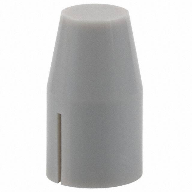
| 描述 | CAP PUSHBUTTON BULLET GRAY开关致动器 PUSH |
| 产品分类 | |
| 品牌 | C&K Components |
| 产品手册 | |
| 产品图片 |
|
| rohs | 符合RoHS无铅 / 符合限制有害物质指令(RoHS)规范要求 |
| 产品系列 | 开关配件,开关致动器,C&K Components F0104F |
| mouser_ship_limit | 该产品可能需要其他文件才能进口到中国。 |
| 数据手册 | http://www.ck-components.com/index.php?module=media&action=Display&cmpref=13342&lang=en&width=&height=&format=&alt= |
| 产品型号 | F0104 |
| 产品 | Actuators |
| 产品培训模块 | http://www.digikey.cn/PTM/IndividualPTM.page?site=cn&lang=zhs&ptm=30457 |
| 产品目录绘图 |
|
| 产品目录页面 | |
| 产品种类 | 开关致动器 |
| 其它名称 | *F0104 |
| 商标 | C&K Components |
| 安装类型 | 卡入式 |
| 尺寸 | 7.19mm 直径 x 12.50mm 高 |
| 工厂包装数量 | 1 |
| 开关类型 | 按钮 |
| 形状 | 子弹形 |
| 标准包装 | 1 |
| 照明 | 不发光 |
| 特性 | - |
| 用于 | Pushbutton Switches |
| 类型 | Pushbutton |
| 系列 | F |
| 设计目的 | FMR Series |
| 配套使用产品/相关产品 | F 系列壁式适配器 |
| 配用 | /product-detail/zh/F6UEE/CKN9666-ND/2054944/product-detail/zh/F2UEE%20TB/CKN10023-ND/2043091/product-detail/zh/F2UOA%20TB/CKN10024-ND/2043090/product-detail/zh/PVA2%20OA%20H2/401-1143-ND/417726/product-detail/zh/PVA2%20EE%20H2/401-1142-ND/417722/product-detail/zh/Y17P12211FP/401-1135-ND/417718/product-detail/zh/PVA1%20EE%20H2/401-1134-ND/417714/product-detail/zh/F4UEE%20AU/401-1227-ND/417521/product-detail/zh/F4UEE/401-1226-ND/417520/product-detail/zh/F2UOA/401-1225-ND/417519/product-detail/zh/F2UEEAU/401-1224-ND/417518/product-detail/zh/F2UEE/401-1223-ND/417517 |
| 颜色 | 灰 |




- 商务部:美国ITC正式对集成电路等产品启动337调查
- 曝三星4nm工艺存在良率问题 高通将骁龙8 Gen1或转产台积电
- 太阳诱电将投资9.5亿元在常州建新厂生产MLCC 预计2023年完工
- 英特尔发布欧洲新工厂建设计划 深化IDM 2.0 战略
- 台积电先进制程称霸业界 有大客户加持明年业绩稳了
- 达到5530亿美元!SIA预计今年全球半导体销售额将创下新高
- 英特尔拟将自动驾驶子公司Mobileye上市 估值或超500亿美元
- 三星加码芯片和SET,合并消费电子和移动部门,撤换高东真等 CEO
- 三星电子宣布重大人事变动 还合并消费电子和移动部门
- 海关总署:前11个月进口集成电路产品价值2.52万亿元 增长14.8%


.jpg)
PDF Datasheet 数据手册内容提取
F Series Pushbutton Switches Features/Benefits Typical Applications A • Up to 10 poles per module • Audio selection • Various contact terminals • Digital equipment interface P u • Various mounting & switch • Medical equipment interface s h ganging configurations b • Mechanical indicator buttons u t • RoHS compliant to n Specifications SWITCHING POWER: F module max. AC/DC: Silver: 50 VA/15W, TYPICAL F OPERATING FORCE: 2U: 6.5N (650 grams); 4U: 6.5N Gold: 1 VA/300 mW. (650 grams); 6U: 7.5N (750 grams); 8U: 9.0N (900 grams); 10U: SWITCHING VOLTAGE: F module max. AC/DC: Silver: 125/30V, 9.0N (900 grams). Gold: 50/30 V. EUROPEAN TYPICAL SF OPERATING FORCE: SWITCHING CURRENT: F module max. AC/DC: Silver: 0.5A/0.5A, 2U: 3.5N±0.5N (350 grams±100 grams); 4U: 5N±1N (500 Gold: 0.04A/0.01A. grams±100 grams); 6U: 6.5N±1N (650 grams±100 grams); 8U: CARRYING CURRENT: Max at d87u = 20C: Silver: < 2A, Gold: <0.5A. 9.0N±1N (900 grams±100 grams). DIELECTRIC STRENGTH (50 Hz, 1 min.): Chassis/contact: ^1500V OPERATING TEMPERATURE RANGE: -40˚C to 70˚C. Between contacts: ^1500V. Materials OPERATING LIFE “OA/EE” (24V/200mA): >105 operations HOUSING: Polycarbonate UL 94V-0 or polyester UL 94V-0. “GR”: >3.5 x 10⁴ operations. ACTUATOR: Polyester UL 94V-0. CONTACT RESISTANCE: Initial: Typical %10 mΩ, max. 20 mΩ MOVABLE CONTACTS: Bimetal brass, silver plated, gold plate After operating life: %100 mΩ over nickel. INSULATION RESISTANCE: ^109 Ω between open contacts, STATIONARY CONTACTS & TERMINALS: Brass, silver plated, ^109 Ω between chassis and contacts. gold plated. CAPACITANCE (at f = 10 kHz): %0.7 pF between 2 contacts. TERMINAL BOARD: Polyester UL 94V-0. TOTAL TRAVEL/LATCHING TRAVEL: 4.7mm/3.3mm (.185 inch/ RETURN SPRING: Music wire. .130 inch). TERMINAL SEAL: RTV adhesive sealant. All models and options are RoHS compliant and compatible. CHASSIS: Steel. NOTE: All models and options are RoHS compliant and compatible. LOCKOUT PIN: Steel. NOTE: Specifications and materials listed above are for switches with standard options. BLOCKERS: Steel. For information on specific and custom switches, consult Customer Service Center. Build-A-Switch To order, simply select desired option from each category and place in the appropriate box. Available options are shown and described on pages A-88 thru A-95. For additional options not shown in catalog, consult Customer Service Center. If requesting only a switch, select either a North American or European switch as noted below. Chassis and buttons are sold separately. If multiple stations are selected, we will assume all switches are the same unless noted otherwise. North American Order Code - Switch Only Designation F F Series Terminal Sealing Contact Material FLT Light touch F series (NONE) None (NONE) Silver, AG ZF Central mounted F series TB Top/bottom AU Gold Contact Arrangement Terminal Style 2U 2PDT (NONE) Solder lugs & PC pins Mechanical Function 4U 4PDT 01A Cut solder lugs Dress nut* OA Momentary 6U 6PDT 01B Cut PC pins, for other configurations, *Central mounted F series only EE Alternate (push-push) 8U 8PDT consult factory GR Interlock 10U 1OPDT Electrical Function (NONE) No dress nut AOR Central release (NONE) BBM Break-Before-Make B Black OASP Momentary with lockout M MBB (special) Make-Before-Break C Chrome GRSP Interlock with lockout Dimensions are shown: Inches (mm) Specifications and dimensions subject to change www.ckswitches.com A-87
F Series Pushbutton Switches A European Order Code - Switch Only n o t t u b Designation h SF F Series Terminal Style Contact Material s ZF Central mounted F series (NONE) Solder lugs & (NONE) Silver, AG u PC pins P Gold P Contact Arrangement LB Cut solder lugs 2U 2PDT PB C ut PC pins, for other Dress nut* 4U 4PDT Mechanical Function configurations, *Central mounted F series only OA Momentary 6U 6PDT consult factory 8U 8PDT EE Alternate (push-push) (NONE) No dress nut GR Interlock Electrical Function B Black (NONE) BBM C Chrome *Minimum order quantities apply. Order Code - Buttons Solid Buttons Mechanical Indicator Buttons Style Style Button Color F01 FMR F01 FA100 Shell Color 01 Black F02 FG* F02 FA101 01 Black 02 White F12 FSC F07 FA120 F13 FSD 03 Red F08 FA2O1 Out Position Color F14 FU12 04 Light gray F11 FA200* 01 Black F15 FSB F16 FE In Position Color F19 FA 02 White F21 F001 06 Yellow 07 Blue 08 Green *Button options for central mounting configurations, 12 Orange use ‘FG’ for central mount with chrome dress nut, use ‘FA200’ for central mount with black dress nut. BUTTON REMOVAL A button of a push-push switch should only be removed in the “OFF” non-latching position. Order Code - Chassis To order a switch with chassis, create the switch part number listed above and add the Chassis part number configurator information at the end of the part number. Note: We do not guarantee or recommend interlocking beyond 10 stations. C No. of Stations Special Acknowledgements 01 thru 23 Comes with standard Spacing between Stations See note .094 (2,4mm) mounting holes 00 Single station Note: Single station chassis 10 10mm available with special mounting 12.5 12.5mm configurations, consult factory. 15 15mm 17.5 17.5mm *Minimum order quantities apply. 20 20mm Dimensions are shown: Inches (mm) Specifications and dimensions subject to change www.ckswitches.com A-88
F Series Pushbutton Switches SWITCHES WITH STANDARD OPTIONS A F2UEE P u s h b u t t o CONTACT LENGTH n ARRANGEMENT DIM ‘L’ 2U 0.827 (21,00) 4U 1.300 (33,00) 6U 1.770 (45,00) 8U 2.240 (57,00) 10U 2.720 (69,00) ZF2UEEBF11010108 CONTACT LENGTH ARRANGEMENT DIM ‘L’ 2U 0.827 (21,00) 4U 1.300 (33,00) 6U 1.770 (45,00) 8U 2.240 (57,00) 10U 2.720 (69,00) DESIGNATION Designation, North America Designation, Europe F F Series SF F Series FLT Light touch F series ZF Central mounted F series ZF Central mounted F series Third Angle Projection Dimensions are shown: Inches (mm) Specifications and dimensions subject to change www.ckswitches.com A-89
F Series Pushbutton Switches CONTACT ARRANGEMENT A n PC MOUNTING o t t u OPTION CODE NO. OF POLES SCHEMATIC b h 2U 2PDT s u P 4U 4PDT 2X 6U 6PDT 3X 8U 8PDT 4X 10U 10PDT 5X MECHANICAL FUNCTION North America Europe OPTION CODE FUNCTION OPTION CODE FUNCTION OA Momentary OA Momentary EE Alternate (push-push) EE Alternate (push-push) GR Interlock GR Interlock AOR Central release OASP Momentary with lockout GRSP Interlock with lockout TERMINAL SEALING (NONE) NO SEAL TB TOP & BOTTOM F2UEE shown in example above. NOTE: Available for North America only Third Angle Projection Dimensions are shown: Inches (mm) Specifications and dimensions subject to change www.ckswitches.com A-90
F Series Pushbutton Switches TERMINAL STYLE A (NONE) 01A 01B SOLDER LUGS & PC PINS CUT SOLDER LUGS (North America) CUT PC PINS (North America) P LB PB u CUT SOLDER LUGS (Europe) CUT PC PINS (Europe) s h b u (.10.6770) tt o n .079 (2.01) ELECTRICAL FUNCTION OPTION CODE FUNCTION (NONE) BBM Non-shorting M MBB Shorting (North America only) CONTACT MATERIAL NORTH AMERICA EUROPE RoHS RoHS OPTION CODE OPTION CODE COMPLIANT * COMPATIBLE * MATERIAL RATING (NONE) (NONE) YES YES SILVER, AG 50 VA/15 W; 125/30 V; 0.5/0.5 A AU P YES YES GOLD 1 VA/300mW; 50/30 V; 0.04 A/0.01 A * Note: See Technical Data section of this catalog for RoHS compliant and compatible definitions and specifications. DRESS NUT (NONE) B C NO DRESS NUT FOR F & F/LT BLACK CHROME DESIGNATIONS PANEL CUTOUT PANEL CUTOUT NOTE: Available with ZF designation and FG button. NOTE: Available with ZF designation and FA200 buttons. Third Angle Projection Dimensions are shown: Inches (mm) Specifications and dimensions subject to change www.ckswitches.com A-91
F Series Pushbutton Switches COLOR SOLID BUTTON A STYLE STYLE n o t F01 F02 F12 t FMR FG FSC u b h s u P F13 FSD F14 FU12 F15 FSB F16 FE F19 FA F21 F001 OPTION CODE COLOR 01 BLACK 02 WHITE 03 RED 04 LT. GRAY Dimensions are shown: Inches (mm) Specifications and dimensions subject to change www.ckswitches.com A-92
F Series Pushbutton Switches SHELL COLOR IN POSITION COLOR MECHANICAL BUTTON STYLE OUT POSITION COLOR A STYLE F02 FA101 P F01 u FA100 s h b u t t o n F07 F08 FA120 FA201 F11 FA200 SHELL COLOR 01 BLACK OUT POSITION COLOR 01 BLACK IN POSITION COLOR OPTION CODE COLOR 02 WHITE 06 YELLOW 07 BLUE 08 GREEN 12 ORANGE Dimensions are shown: Inches (mm) Specifications and dimensions subject to change www.ckswitches.com A-93
F Series Pushbutton Switches SPACING CHASSIS A NO. OF STATIONS NUMBER OF STATIONS n o C00 Thru C10 t Comes with standard 0.094 (2,44mm) mounting holes t u b NOTE: Single station chassis available with mounting configurations, consult factory. h s SPACING u P 00 SINGLE STATION 10 10mm No. of Stations Dim. ‘A’ Dim. ‘B’ Tolerance 1.182 1.418 2 0.005 (30,02) (36,02) 1.575 1.811 3 0.010 (40,01) (46,00) 1.969 2.205 4 0.010 (50,01) (56,01) .394 2.363 2.599 (10,0) 5 (60,02) (66,01) 0.010 2.757 2.993 6 0.015 (70,03) (76,02) 3.150 3.386 7 0.015 (80,01) (86,00) 3.544 3.780 8 0.015 (90,02) (96,01) 3.938 4.174 9 0.015 (100,03) (106,02) 4.331 4.567 10 0.015 (110,01) (116,00) 12.5 12.5mm No. of Stations Dim. ‘A’ Dim. ‘B’ Tolerance 1.200 1.436 2 0.005 (30,48) (36,47) 1.692 1.928 3 0.010 (42,98) (48,97) 2.184 2.420 4 0.010 (55,47) (61,47) .492 (12,5) 5 2.676 2.912 0.010 (67,97) (73,96) 3.169 3.405 6 0.015 (80,49) (86,49) 3.661 3.897 7 0.015 (92,99) (98,98) 4.153 4.389 8 0.015 (105,49) (111,48) 4.645 4.881 9 0.015 (117,98) (123,98) 5.137 5.373 10 0.015 (130,48) (136,47) Third Angle Projection Dimensions are shown: Inches (mm) Specifications and dimensions subject to change www.ckswitches.com A-94
F Series Pushbutton Switches SPACING CHASSIS NO. OF STATIONS A SPACING P u 15 s 15mm h b No. of Stations Dim. ‘A’ Dim. ‘B’ Tolerance u 2 1.374 1.615 0.005 t (34,90) (41,02) t o 3 1.969 2.205 0.010 n (50,01) (56,01) 2.560 2.796 .591 4 0.010 (65,02) (71,02) (15,0) 3.150 3.386 5 0.010 (80,01) (86,00) 3.741 3.977 6 0.015 (95,02) (101,02) 4.332 4.568 7 0.015 (110,03) (116,03) 4.922 5.158 8 0.015 (125,02) (131,01) 5.513 5.749 9 0.015 (140,03) (146,02) 6.103 6.339 10 0.015 (155,02) (161,01) 17.5 17.5mm No. of Stations Dim. ‘A’ Dim. ‘B’ Tolerance 1.477 1.713 2 0.005 (37,52) (43,51) 2.166 2.402 3 0.010 (55,02) (61,01) 2.855 3.091 4 0.010 (75,52) (78.51) 3.544 3.780 5 0.010 (90,02) (96,01) 4.233 4.469 6 0.015 (107,52) (113,51) 4.922 5.158 7 0.015 (125,02) (131,01) 5.611 5.847 8 0.015 (142,52) (148.51) 6.300 6.536 9 0.015 (160,02) (166,01) 6.989 7.225 10 0.015 (177,52) (183,52) 20 20mm No. of Stations Dim. ‘A’ Dim. ‘B’ Tolerance 1.575 1.811 2 0.005 (40,01) (46,00) 2.363 2.599 3 0.010 (60,02) (66,01) 3.150 3.386 4 0.010 (80,01) (86,00) 3.938 4.174 5 0.010 (100,03) (106,02) 4.725 4.961 6 0.015 (120,02) (126,01) 5.512 5.748 7 0.015 (140,00) (146,00) 6.300 6.536 8 0.015 (160,02) (166,01) 7.087 7.323 9 0.015 (180,01) (186,00) 7.875 8.111 10 0.015 (200,03) (206,02) Third Angle Projection Dimensions are shown: Inches (mm) Specifications and dimensions subject to change www.ckswitches.com A-95
Mouser Electronics Authorized Distributor Click to View Pricing, Inventory, Delivery & Lifecycle Information: C &K Components: 539-0092-009 C &K Switches: 21125 110176 F08010112 F11010108 F08010106 100100-7152 170100-2506 F02010112 F1602 F1404 F07010102 100200-1016 C1010 3505 F2UEETB C10175 F1301 169-0019-002 169-0019-003 169-0019-001 169-0019-005 RELBARF7X15NICKELPLTD ZF UNTERTEIL ZF MUTTER ZF SCHRAUBBLENDE BK ZF0BERTEIL
Mouser Electronics Authorized Distributor Click to View Pricing, Inventory, Delivery & Lifecycle Information: C &K Switches: F1604 51902 (F8UEE) F1504 F07-01 F1904 F15-02 21125 F08010102 F08010108 F11010102 F11010112 F02010108 F08010107 F6UOATB 115-0058-001 F0102 F0104 F0202 F0204 F1203 F1201 F1204 F0203 FLT 2U EE 01A FLT 4U EE 01A 100100-2019 100100-4004 F02010112 SF2UEE SF2UEELB SF4UEE SF 2U OA SF4UPEE SF2US2EE SF2UPEE SF4U72EE SF 2U P EE LB SF 4U EE LB SF 4U P EE LB SF 6U EE LB F0UOACUTREAR F01010107 F01010112 F02010106 F050101OPQ F01010102 F0208 F2U0A F07010112 F01010106 F02010107 F01010108 F0UEEW2UPLGR F2U0ATB F6U0A C0715 F0U0ACUTREAR F4U0A F4U0ATB F1502 F4U0ASP F4U0ATBAU F6U0ATB F8U0A
 Datasheet下载


