ICGOO在线商城 > 电路保护 > TVS - 变阻器,MOV > EZJ-PZV120RA
 Datasheet下载
- 型号: EZJ-PZV120RA
- 制造商: Panasonic Corporation
- 库位|库存: xxxx|xxxx
- 要求:
| 数量阶梯 | 香港交货 | 国内含税 |
| +xxxx | $xxxx | ¥xxxx |
查看当月历史价格
查看今年历史价格
EZJ-PZV120RA产品简介:
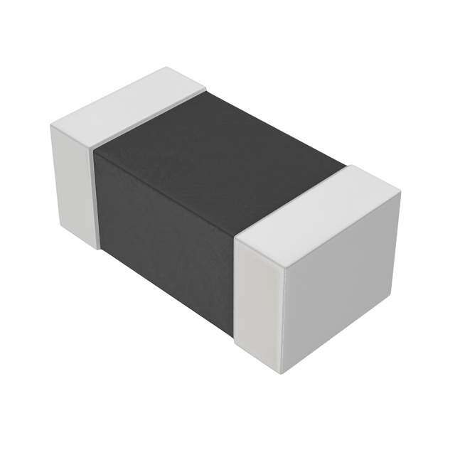
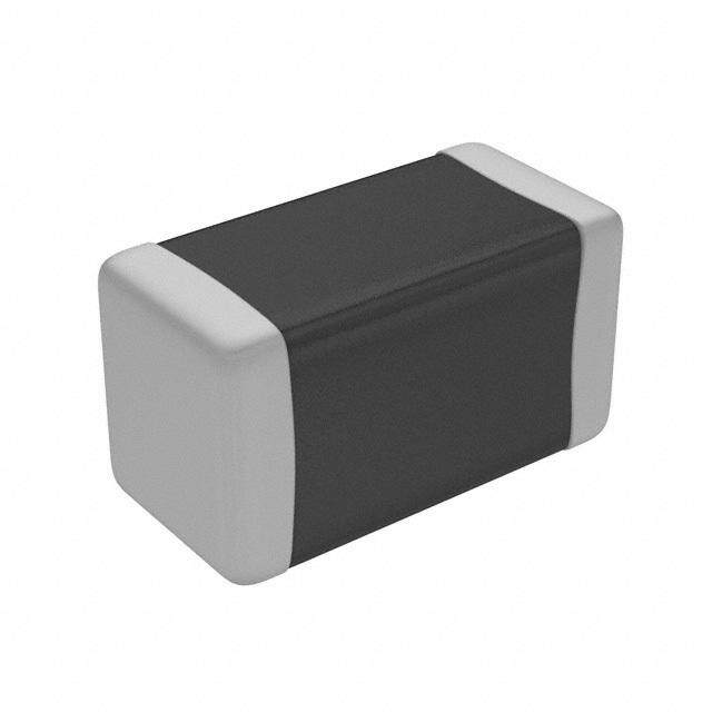
ICGOO电子元器件商城为您提供EZJ-PZV120RA由Panasonic Corporation设计生产,在icgoo商城现货销售,并且可以通过原厂、代理商等渠道进行代购。 EZJ-PZV120RA价格参考。Panasonic CorporationEZJ-PZV120RA封装/规格:TVS - 变阻器,MOV, 12V 1A Varistor 1 Circuit Surface Mount, MLCV 0201 (0603 Metric)。您可以下载EZJ-PZV120RA参考资料、Datasheet数据手册功能说明书,资料中有EZJ-PZV120RA 详细功能的应用电路图电压和使用方法及教程。
Panasonic Electronic Components的EZJ-PZV120RA是一款TVS(瞬态电压抑制器)变阻器,属于MOV(金属氧化物压敏电阻)类别。这款元件主要用于保护电子设备免受过电压瞬变的影响,适用于多种应用场景。

 应用场景:

1. 电源线保护:
   EZJ-PZV120RA可以用于电源线的过电压保护,防止由于雷击、电涌或其他瞬变电压对电源系统造成损坏。它能够迅速响应并吸收瞬时高能量,确保电源系统的稳定性和可靠性。

2. 通信设备:
   在通信设备中,如路由器、调制解调器和交换机等,该元件可以有效保护信号传输线路免受静电放电(ESD)、雷击感应和其他瞬态电压的损害,确保数据传输的连续性和完整性。

3. 工业控制系统:
   工业自动化系统中的传感器、控制器和执行器等关键组件容易受到外部环境中的瞬变电压影响。EZJ-PZV120RA可以在这些环境中提供可靠的保护,防止因电压波动导致的设备故障或停机。

4. 家电产品:
   家用电器如空调、冰箱、洗衣机等,通常暴露在复杂的电磁环境中。EZJ-PZV120RA可以安装在这些设备的电源输入端或敏感电路部分,吸收可能的瞬态电压,延长设备的使用寿命并提高安全性。

5. 汽车电子:
   汽车中的电子控制单元(ECU)、车载娱乐系统和其他电子模块也需要有效的过电压保护。EZJ-PZV120RA能够在车辆启动、发电机脉冲以及其他电气干扰情况下,保护这些关键电子部件不受损坏。

6. 消费电子产品:
   对于智能手机、平板电脑、笔记本电脑等便携式设备,EZJ-PZV120RA可以提供针对静电放电和瞬态电压的保护,确保设备在各种使用环境下都能正常工作。

总之,EZJ-PZV120RA凭借其快速响应特性和高能量吸收能力,广泛应用于需要过电压保护的各种电子设备和系统中,确保其稳定运行和长寿命。
| 参数 | 数值 |
| 产品目录 | |
| 描述 | VARISTOR 12V 1A 0201压敏电阻 0201, 12V, 1A MAX CLAMP 40V |
| 产品分类 | |
| 品牌 | Panasonic |
| 产品手册 | |
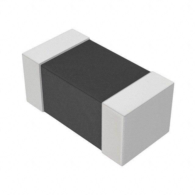
| 产品图片 |
|
| rohs | 符合RoHS无铅 / 符合限制有害物质指令(RoHS)规范要求 |
| 产品系列 | Panasonic EZJ-PZV120RA- |
| 数据手册 | |
| 产品型号 | EZJ-PZV120RA |
| 产品 | MLV |
| 产品种类 | 压敏电阻 |
| 其它名称 | P15075CT |
| 包装 | Digi-Reel® |
| 变阻器电压 | 12 V |
| 商标 | Panasonic |
| 外壳代码-in | 0201 |
| 外壳代码-mm | 0603 |
| 外壳宽度 | 0.3 mm |
| 安装 | SMD/SMT |
| 宽度 | 0.3 mm |
| 封装 | Reel |
| 封装/外壳 | 0201(0603 公制) |
| 封装/箱体 | 0201 (0603 metric) |
| 尺寸 | 0.3 mm W x 0.6 mm L x 0.3 mm H |
| 峰值浪涌电流 | 1 A |
| 工作温度范围 | - 40 C to + 85 C |
| 工厂包装数量 | 15000 |
| 最大AC电压 | - |
| 最大DC电压 | 7.5VDC |
| 标准包装 | 1 |
| 电压额定值DC | 7.5 V |
| 电容 | 20 pF |
| 电流-浪涌 | 1A |
| 电路数 | 1 |
| 端接类型 | SMD/SMT |
| 系列 | EZJ |
| 能量 | - |


- 商务部:美国ITC正式对集成电路等产品启动337调查
- 曝三星4nm工艺存在良率问题 高通将骁龙8 Gen1或转产台积电
- 太阳诱电将投资9.5亿元在常州建新厂生产MLCC 预计2023年完工
- 英特尔发布欧洲新工厂建设计划 深化IDM 2.0 战略
- 台积电先进制程称霸业界 有大客户加持明年业绩稳了
- 达到5530亿美元!SIA预计今年全球半导体销售额将创下新高
- 英特尔拟将自动驾驶子公司Mobileye上市 估值或超500亿美元
- 三星加码芯片和SET,合并消费电子和移动部门,撤换高东真等 CEO
- 三星电子宣布重大人事变动 还合并消费电子和移动部门
- 海关总署:前11个月进口集成电路产品价值2.52万亿元 增长14.8%

PDF Datasheet 数据手册内容提取
Multilayer Varistors Multilayer Varistor for ESD pulse [DC voltage lines/High speed signal lines] Series : EZJZ, EZJP ■ ■ Features Handling Precautions ● Excellent ESD suppression due to advanced material Please see pages 291 to 296 technology ● Meets IEC61000-4-2, Level 4 standard ● Can replace 2 Zener Diodes and 1 Capacitor ● Low capacitance versions for DC voltage lines of high ■ Packaging Methods speed busses ● Ultra low capacitance for signal lines of high speed Please see pages 290, 360 busses ● Ideal usage for USB 2.0, IEEE1394, and HDMI high speed data busses ■ Explanation of Part Numbers 1 2 3 4 5 6 7 8 9 10 11 12 E Z J Z 0 V 2 7 0 E A (Example) ProductCode DesignCode Series Code PackagingStyleCode CapacitanceCode DesignCode Z EZJZseries V 0402,0603PaperTaping A 3pF G 100pF Nil Cap.Tolerance:max. P EZJPseries R 20pF H 150pF B Cap.Tolerance:±0.1pF D 27pF J 220pF C Cap.Tolerance:±0.25pF SizeCode NomiralVaritorVoltage E 47pF K 330pF D Cap.Tolerance:±0.50pF Z 0201 Tdheenofitrestthaendfirssetc2onnudmdbigeirtss W 56pF M 680pF K Cap.Tolerance:±10% 0 0402 ofthevaristorvoltageand F 68pF M Cap.Tolerance:±20% 1 0603 thethirddigitindicatesthe numberofzerosfollowing. Below3pF,the10or11th Thedecimalpointdenotes positionoftheP/Nindicatesthe inR. capacitancevalueasfollows: 2.0pF·····20, 1.5p·····F15 ■ Construction No. Name 1 Semiconductive Ceramics 3 2 Internal electrode 4 5 3 Substrate electrode 2 1 4 Terminal electrode Intermediate electrode 5 External electrode ■ Dimensions in mm (not to scale) L W Size Code Size(inch) L W T L1, L2 Z 0201 0.60±0.03 0.30±0.03 0.30±0.03 0.15±0.05 T 0 0402 1.00±0.05 0.50±0.05 0.50±0.05 0.2±0.1 L1 L2 1 0603 1.6±0.1 0.8±0.1 0.8±0.1 0.3±0.2 Design and specifi cations are each subject to change without notice. Ask factory for the current technical specific ations before purchase and/or use. Should a safety concern arise regarding this product, please be sure to contact us immediately. 00 Sep. 2010 – 278 –
Multilayer Varistors Multilayer Varistor, Low Capacitance Type [High speed signal lines] ■ ■ Features Recommended Applications ● Multilayer monolithic ceramic construction for high Mobile phone Antenna circuit, External IF speed signal lines DSC, DVC USB2.0, IEEE1394 ● Ideal usage for USB 2.0, IEEE1394, and HDMI high PC, PDA USB2.0, IEEE1394, LAN1000BASE speed data busses TV, DVD USB2.0, IEEE1394, HDMI ● Capacitance : 0.8 to 2.1 pF typ. Game console Controller, External IF ■ Ratings and Characteristics Maximum Nominal varistor Capacitance (pF) Maximum ESD Size Part No. allowable voltage voltage at 1MHz IEC61000-4-2 DC (V) at 1mA (V) EZJZ0V80010 10 80 1 max. [0.8 typ.] EZJZ0V80015D 5 80 1.5±0.5 0402 EZJZ0V500AA 5 50 3 max. [2.1 typ.] EZJZ0V800AA 18 80 3 max. [2.1 typ.] EZJZ0V171AA 18 170 3 max. [2.1 typ.] Contact discharge : 8kV EZJZ1V80010 10 80 1 max. [0.8 typ.] EZJZ1V500AA 5 50 3 max. [2.1 typ.] 0603 EZJZ1V800AA 18 80 3 max. [2.1 typ.] EZJZ1V171AA 18 170 3 max. [2.1 typ.] ● Operating Temperature Range : –40 to 85 °C ✽ Recommend soldering method : Reflo w soldering ■ Voltage vs. Current Max.LeakageCurrent Max.ClampingVoltage 1000 EZJZ(cid:1)V171AA V) EZJZ(cid:1)V171AA EZJZ(cid:1)V800AA age(100 EZJZ(cid:1)V500AA olt V EZJZ(cid:1)V800AA EZJZ(cid:1)V500AA (Typicalcurve) 10 10–6 10–5 10–4 10–3 10–2 10–1 100 101 Current(A) Design and specifi cations are each subject to change without notice. Ask factory for the current technical specific ations before purchase and/or use. Should a safety concern arise regarding this product, please be sure to contact us immediately. 00 Sep. 2010 – 279 –
Multilayer Varistors ■ ■ Frequency vs. Capacitance Frequency vs. Impedance 100 10000000 3pFmax.[2.1pFtyp.] 1000000 1.5pFtyp. 3pFmax.[2.1pFtyp.] 100000 pF) 10 1pFmax.[0.8pFtyp.] (cid:1)) 1.5pFtyp. e( e(10000 1pFmax.[0.8pFtyp.] c c n n a a Capacit 1 Imped 1000 100 10 (Typicalcurve) (Typicalcurve) 0.1 1 1 10 100 1000 10000 1 10 100 1000 10000 Frequency(MHz) Frequency(MHz) ■ Frequency vs. Transmission 10 3pFmax.[2.1pFtyp.] 5 1.5pFtyp. 1pFmax.[0.8pFtyp.] 0 –5 B) d–10 ( n atio–15 u en–20 Att –25 –30 –35 (Typicalcurve) –40 1 10 100 1000 10000 Frequency(MHz) Design and specifi cations are each subject to change without notice. Ask factory for the current technical specific ations before purchase and/or use. Should a safety concern arise regarding this product, please be sure to contact us immediately. 00 Sep. 2010 – 280 –
Multilayer Varistors Multilayer Varistor, Low Voltage Type (Standard Type) [DC voltage lines/Low speed signal lines] ■ ■ Features Recommended Applications Multilayer monolithic ceramic construction for use SW, LCD, LED, Audio terminal, protecting DC voltage lines or signal lines Mobile phone Battery pack, Memory card, External IF ● Circuit voltage DSC, DVC SW, LCD, LED, USB voltage 234600 PTVC,, DPVDDA ASWud, ioL,C VDid, eLoE Dte, rUmSinBal wable(V) 1136 Audio Audio terminal, Microphone, Receiver oC 11 allD 6.7 Game console Controller, External IF um 5.6 m 3.7 xi Ma 3 5 12 24 40 CircuitvoltageDC(V) ● Varistor voltage : 6.8 to 65 V [at 1 mA] ● Capacitance : 8.5 to 420 pF typ. [at 1 MHz] ■ Ratings and Characteristics Maximum Nominal Maximum allowable varistor Capacitance (pF) peak current Maximum ESD Size Part No. voltage voltage at 8/20µs, 2times IEC61000-4-2 DC (V) at 1mA (V) at 1MHz at 1kHz (A) EZJPZV6R8JA 3.7 6.8 220 max. [180 typ.] 175 typ. 5 EZJPZV6R8GA 3.7 6.8 100 max. [ 85 typ.] 100 typ. 5 EZJPZV080GA 5.6 8 100 max. [ 85 typ.] 100 typ. 5 EZJPZV120GA 7.5 12 100 max. [ 85 typ.] 100 typ. 5 0201 EZJPZV120DA 7.5 12 27 max. [ 22 typ.] 33 typ. 1 EZJPZV120RA 7.5 12 20 max. [ 15 typ.] 18 typ. 1 EZJPZV150RA 9 15 20 max. [ 15 typ.] 18 typ. 1 EZJPZV270RA 16 27 20 max. [ 15 typ.] 16.5 typ. 1 EZJPZV270BA 16 27 10 max. [8.5 typ.] 10 typ. 1 EZJP0V6R8MA 3.7 6.8 680 max. [420 typ.] 650 typ. 20 EZJP0V6R8GA 3.7 6.8 100 max. [ 85 typ.] 100 typ. 3 EZJP0V080MA 5.6 8 680 max. [420 typ.] 650 typ. 20 EZJP0V080KA 5.6 8 330 max. [290 typ.] 480 typ. 15 EZJP0V080GA 5.6 8 100 max. [ 65 typ.] 100 typ. 3 EZJP0V080DA 5.6 8 27 max. [ 22 typ.] 33 typ. 1 Contact discharge 0402 EZJZ0V120JA 6.7 12 220 max. [150 typ.] 175 typ. 10 8 kV EZJZ0V180HA 11 18 150 max. [120 typ.] 140 typ. 10 EZJZ0V220HA 13 22 150 max. [100 typ.] 116 typ. 10 EZJP0V270EA 16 27 47 max. [ 33 typ.] 37 typ. 4 EZJP0V270RA 16 27 20 max. [ 15 typ.] 16.5 typ. 1 EZJZ0V420WA 30 42 56 max. [ 40 typ.] 45 typ. 10 EZJZ0V650DA 40 65 27 max. [ 22 typ.] 33 typ. 5 EZJZ1V120KA 6.7 12 330 max. [250 typ.] 290 typ. 20 EZJZ1V180JA 11 18 220 max. [180 typ.] 210 typ. 20 EZJZ1V220JA 13 22 220 max. [160 typ.] 185 typ. 20 EZJZ1V270GA 16 27 100 max. [ 85 typ.] 100 typ. 20 0603 EZJZ1V270EA 16 27 47 max. [ 33 typ.] 37 typ. 20 EZJZ1V270RA 16 27 20 max. [ 15 typ.] 16.5 typ. 3 EZJZ1V330GA 26 33 100 max. [ 85 typ.] 100 typ. 20 EZJZ1V420FA 30 42 68 max. [ 55 typ.] 63 typ. 15 EZJZ1V650DA 40 65 27 max. [ 22 typ.] 33 typ. 5 ● Operating Temperature Range : –40 to 85 °C ✽ Recommend soldering method : Reflo w soldering Maximum Allowable Voltage Maximum DC Voltage that can be applied continuously within the operating temperature range Varistor Voltage Varistor starting voltage between terminals at DC 1 mA, also known as Breakdown voltage Maximum Peak Current Varistor’s maximum current under the standard pulse 8/20µs, 2 times based Varistor’s maximum voltage under ESD based on IEC61000-4-2, 10 times Maximum ESD (5 times of each positive-negative polarity) Design and specifi cations are each subject to change without notice. Ask factory for the current technical specific ations before purchase and/or use. Should a safety concern arise regarding this product, please be sure to contact us immediately. 00 Sep. 2010 – 281 –
Multilayer Varistors ■ Voltage vs. Current ● EZJP Series ● EZJZ Series Max.LeakageCurrent Max.ClampingVoltage Max.LeakageCurrent Max.ClampingVoltage 100 300 200 EZJZ(cid:1)V650(cid:1)A EZJZ(cid:1)V650(cid:1)A EZJP(cid:1)V270RA EZJZ(cid:1)V420(cid:1)A EZJZ(cid:1)V420(cid:1)A EZJP(cid:1)V270RA EEZZJJPPZZVV112500GRAA 100 EZJZ(cid:1)V330(cid:1)A EEZZJJZZ(cid:1)(cid:1)VV323700(cid:1)(cid:1)AA EZJPZV150RA EZJP(cid:1)V080(cid:1)A EZJZ(cid:1)V220(cid:1)A EZJP(cid:1)V6R8(cid:1)A EZJZ(cid:1)V180(cid:1)A V) V) EZJZ(cid:1)V120(cid:1)A ( ( e10 e g g a a olt olt10 V V EZJZ(cid:1)V270(cid:1)A EZJPZV120GA EZJZ(cid:1)V220(cid:1)A EZJP(cid:1)V080(cid:1)A EZJZ(cid:1)V180(cid:1)A EZJP(cid:1)V6R8(cid:1)A EZJZ(cid:1)V120(cid:1)A (Typicalcurve) (Typicalcurve) 1 1 10–6 10–5 10–4 10–3 10–2 10–1 100 101 10–6 10–5 10–4 10–3 10–2 10–1 100 101 102 Current(A) Current(A) ■ Frequency vs. Capacitance ● EZJP Series ● EZJZ Series 10000 10000 330pFmax. 680pFmax. 220pFmax. 1000 330pFmax. 1000 100pFmax. F) F) (p 100pFmax. (p 47pFmax. e e c c an100 27pFmax. an100 20pFmax. acit 20pFmax. acit p p a 10pFmax. a C C 10 10 (Typicalcurve) (Typicalcurve) 1 1 0.1 1 10 100 1000 10000 0.1 1 10 100 1000 10000 Frequency(MHz) Frequency(MHz) ■ Frequency vs. Transmission ● EZJP Series ● EZJZ Series 10 10pFmax. 10 20pFmax. 20pFmax. 0 27pFmax. 0 47pFmax. 100pFmax. –10 –10 B) B) d d ( 20 ( 20 n n o o ati ati 100pFmax. enu–30 330pFmax. enu–30 220pFmax. Att 680pFmax. Att 330pFmax. –40 –40 –50 –50 (Typicalcurve) (Typicalcurve) –60 –60 0.1 1 10 100 1000 10000 0.1 1 10 100 1000 10000 Frequency(MHz) Frequency(MHz) Design and specifi cations are each subject to change without notice. Ask factory for the current technical specific ations before purchase and/or use. Should a safety concern arise regarding this product, please be sure to contact us immediately. 00 Sep. 2010 – 282 –