ICGOO在线商城 > EX-L261-J
 Datasheet下载
- 型号: EX-L261-J
- 制造商: Panasonic Corporation
- 库位|库存: xxxx|xxxx
- 要求:
| 数量阶梯 | 香港交货 | 国内含税 |
| +xxxx | $xxxx | ¥xxxx |
查看当月历史价格
查看今年历史价格
EX-L261-J产品简介:
ICGOO电子元器件商城为您提供EX-L261-J由Panasonic Corporation设计生产,在icgoo商城现货销售,并且可以通过原厂、代理商等渠道进行代购。 提供EX-L261-J价格参考¥1679.46-¥1767.85以及Panasonic CorporationEX-L261-J封装/规格参数等产品信息。 你可以下载EX-L261-J参考资料、Datasheet数据手册功能说明书, 资料中有EX-L261-J详细功能的应用电路图电压和使用方法及教程。
| 参数 | 数值 |
| 产品目录 | |
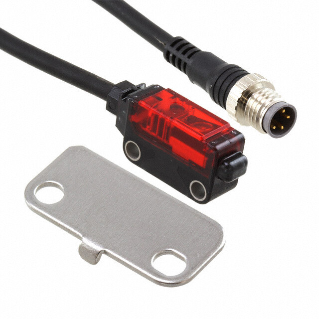
| 描述 | SENSOR LASER NPN 20-50MM 12-24V |
| 产品分类 | |
| 品牌 | Panasonic Industrial Automation Sales |
| 数据手册 | |
| 产品图片 |
|
| 产品型号 | EX-L261-J |
| rohs | 无铅 / 符合限制有害物质指令(RoHS)规范要求 |
| 产品系列 | EX-L200 |
| 侵入防护 | IP67 |
| 光源 | 红色激光二极管 (650nm) |
| 其它名称 | 1110-1518 |
| 响应时间 | 0.5ms |
| 工作温度 | -10°C ~ 55°C |
| 感应方法 | 反射式,聚合 |
| 感应距离 | 0.787" ~ 1.969" (20mm ~ 50mm) ADJ |
| 标准包装 | 1 |
| 电压-电源 | 12 V ~ 24 V |
| 电缆长度 | 78.740"(2000.00mm) |
| 调节类型 | 可调 |
| 输出配置 | NPN - 开路集电极 |
| 连接方法 | 线缆 |


- 商务部:美国ITC正式对集成电路等产品启动337调查
- 曝三星4nm工艺存在良率问题 高通将骁龙8 Gen1或转产台积电
- 太阳诱电将投资9.5亿元在常州建新厂生产MLCC 预计2023年完工
- 英特尔发布欧洲新工厂建设计划 深化IDM 2.0 战略
- 台积电先进制程称霸业界 有大客户加持明年业绩稳了
- 达到5530亿美元!SIA预计今年全球半导体销售额将创下新高
- 英特尔拟将自动驾驶子公司Mobileye上市 估值或超500亿美元
- 三星加码芯片和SET,合并消费电子和移动部门,撤换高东真等 CEO
- 三星电子宣布重大人事变动 还合并消费电子和移动部门
- 海关总署:前11个月进口集成电路产品价值2.52万亿元 增长14.8%


PDF Datasheet 数据手册内容提取
Amplifi er Built-in ULTRA-COMPACT LASER SENSOR EX-L200 SERIES FDA Conforming to Conforming to EMC Directive FDA regulations Unrivaled world smallest* Self-Contained High Precision Laser Sensor * Based on research conducted by our company as of January 2012 2012.04 panasonic.net/id/pidsx/global
Introducing world smallest* amplifi er built-in laser sensor Due to the customized IC and optical design, high General-purpose photoelectric sensor precision detection is fulfi lled in a world smallest size with directivity and visibility achievable only by laser. The laser adopted is Class 1 (JIS / IEC / FDA) laser that is safe to use, so that there is no need to separate the areas of sensor usage. 12 Depth mm 0.472 in * Based on research conducted by our company as of January 2012 W8.2 × H23.4 × D12 mm W0.323 × H0.921 × D0.472 in (Thru-beam type) Thru-beam type (EX-L211, EX-L212) MMiinnuuttee oobbjjeecctt ddeetteeccttiioonn ttyyppee ((EEXX--LL221111)) Sensing range TThhee bbeeaamm iiss ppuurrppoosseellyy wwiiddeenneedd ttoo hhaavvee aa lloowweerr bbeeaamm ddeennssiittyy aanndd lliittttllee bbeeaamm Minute object detection type (EX-L211): sspprreeaadd ssoo tthhaatt wwhheenn ddeetteeccttiinngg mmiinnuuttee oobbjjeeccttss,, eevveenn aa sslliigghhtt cchhaannggee iinn tthhee 1 m 3.281 ft lliigghhtt rreecceeiivveedd iinntteennssiittyy wwiillll nnoott bbee mmiisssseedd.. SSppoott ssiizzee:: 66 ×× 44 mmmm 0.236 × 0.157 in aapppprrooxx.. Long sensing range type (EX-L212): ((VViissuuaall rreeffeerreennccee vvaalluuee aatt aa sseennssiinngg ddiissttaannccee ooff 11 mm 3.281 ft)) 3 m 9.843 ft LLoonngg sseennssiinngg rraannggee ttyyppee ((EEXX--LL221122)) AA lloonngg rraannggee ddeetteeccttiioonn ooff 33 mm 9.843 ft iiss aacchhiieevveedd.. HHiigghh pprreecciissiioonn ddeetteeccttiioonn wwiitthh mmiinniimmuumm bbeeaamm sspprreeaadd iiss ppoossssiibbllee eevveenn iinn aa lloonngg rraannggee.. SSppoott ssiizzee:: 88 ×× 55..55 mmmm 0.315 × 0.217 in aapppprrooxx.. ((VViissuuaall rreeffeerreennccee vvaalluuee aatt aa sseennssiinngg ddiissttaannccee ooff 11 mm 3.281 ft)) Refl ective type (EX-L291) LLoonngg sseennssiinngg rraannggee ttyyppee Sensing range AAcchhiieevviinngg eeaassee ooff iinnssttaallllaattiioonn aanndd 44 mm 13.123 ft lloonngg sseennssiinngg rraannggee.. SSppoott ssiizzee:: 66 ×× 44 mmmm 0.236 × 0.157 in aapppprrooxx.. 4 m 13.123 ft ((VViissuuaall rreeffeerreennccee vvaalluuee aatt aa sseennssiinngg ddiissttaannccee ooff 11 mm 3.281 ft)) Spot refl ective type (EX-L221) MMiinnuuttee oobbjjeecctt ddeetteeccttiioonn ttyyppee HHiigghhllyy pprreecciissee sseennssiinngg wwiitthh mmiinniimmuumm 00..0011 mmmm 0.0004 in ddiiaammeetteerr.. Sensing range MMaannyy aapppplliiccaattiioonnss aarree ppoossssiibbllee dduuee ttoo tthhee 330000 mmmm 11.811 in lloonngg sseennssiinngg rraannggee.. SSppoott ssiizzee:: øø11 mmmm ø0.039 in 45 300 mm to mm ((VViissuuaall rreeffeerreennccee vvaalluuee aatt aa sseennssiinngg ddiissttaannccee ooff 330000 mmmm 11.811 in)) 1.772 in to 11.811 in Convergent refl ective type (EX-L261, EX-L262) SSppoott ttyyppee ((EEXX--LL226611)) Sensing range HHiigghhllyy pprreecciissee sseennssiinngg wwiitthh mmiinniimmuumm 00..0011 mmmm 0.0004 in ddiiaammeetteerr.. Spot type (EX-L261): NNoott aaffffeecctteedd bbyy tthhee bbaacckkggrroouunndd,, aanndd aabbllee ttoo rreelliiaabbllyy sseennssee uunneevveennllyy--ccoolloorreedd wwoorrkkppiieecceess.. 20 50 mm to mm SSppoott ssiizzee:: øø11 mmmm ø0.039 in ((VViissuuaall rreeffeerreennccee vvaalluuee aatt aa sseennssiinngg ddiissttaannccee ooff 5500 mmmm 1.969 in)) 0.787 in to 1.969 in LLiinnee ssppoott ttyyppee ((EEXX--LL226622)) AAbbllee ttoo sseennssee tthhiinn,, gglloossssyy oorr ccuurrvveedd--ssuurrffaaccee wwoorrkkppiieecceess dduuee ttoo lliinnee bbeeaamm.. Sensing range SSppoott ssiizzee:: 11 ×× 55 mmmm 0.039 × 0.197 in aapppprrooxx.. Line spot type (EX-L262): ((VViissuuaall rreeffeerreennccee vvaalluuee aatt aa sseennssiinngg ddiissttaannccee ooff 5500 mmmm 1.969 in)) 20 70 mm to mm 0.787 in to 2.756 in 2
Minute object detection type (EX-L211, EX-L221) Highly accurate detection ● Suitable for positioning and minute object detection A repeatability of 0.02 mm 0.0008 in or less at a range of from 100 to 200 mm 3.937 to 7.874 in makes this type best suitable for positioning applications (EX-L221). Moreover, it boasts a top-class detection precision in the compact laser sensor category with the gold wire of ø0.01 mm ø0.0004 in. Model No. Minimum sensing object Repeatabillty (Minute object detection type) (Typical) (Typical) EX-L211 (Thru-beam type) ø0.3 mm ø0.012 in 0.01 mm 0.0004 in or less EX-L221 (Refl ective type) ø0.01 mm ø0.0004 in 0.02 mm 0.0008 in or less Detecting tip of very thin pipe * Typical values when the sensitivity adjuster is optimally adjusted. EX-L200 series Dependable technology yields high precision ● I ncorporating a high-precision ● S mall receiver aperture The secret to high aspheric glass lens for precision detection. precision ø0.5 Light aberrations are reduced and a high defi nition Errant beams are eliminated by the mm ø0.020 laser spot is possible by incorporating a molded ø0.5 mm ø0.020 in receiver aperture. in aspheric glass lens. Only beams entering the aperture are slit The secret to high precision used, making for high-precision sensing. Molded aspheric glass lenses Thru-beam type (EX-L211, EX-L212) Easy beam-axis alignment Stability indicator ● V isual positioning is easy due to silhouetting Sensing object (Green) (Lead of mechanical pencil) a sensing object against a receiver. Visually confi rm the optimal receiver position, adjusting the beam axis by aligning the objects while watching the red spot on the beam alignment screen. The diagram on the right shows an example with the lead of a mechanical pencil being detected through visual adjustment. Bright red spot Shadow of sensing Beam alignment screen object (Lead of mechanical pencil) Convergent refl ective type (EX-L261, EX-L262) Stable convergent distance sensing ● F or sensing when background object presents ● F or sensing unevenly-colored workpieces Due to convergent distance sensing, the background has very little effect, enabling stable sensing. Sensitivity adjuster allows you Able to reliably sense unevenly-colored to adjust sensitivity to avoid sensing background objects when the Sensitivity workpieces. adjuster distance between the workpiece and background objects is small. ● F or sensing thin, glossy or curved-surface workpieces (Line spot type EX-L262) Able to sense glossy or curved-surface workpieces, such as PCB and metallic pippeess,, due to a wide line laser beam. 3
EX-L200 SERIES Other Features Same mounting pitch as Strong against water and dust with ultra-compact photoelectric sensor protection structure IP67 Same mounting pitch as ultra-compact photoelectric sensor EX-20 series Mounting pitch* EX-L200 series EX-20 series * Thru-beam type: 13 mm 0.512 in Refl ective type: 16 mm 0.630 in EX-L200 series has the same mounting pitch as ultra-compact The sensor can be used even in environment where water or photoelectric sensor EX-20 series so that the time taken in dust present because of its protection structure IP67. designing is saved. Safe Class 1 Lasers This sensor incorporating safe Class 1 lasers (JIS/IEC/FDA) as its light source. There is no need to use different sensors in different regions such as Europe or North America. M3 screw used for secure tightening Sensitivity adjuster (EX-L211, EX-L221, EX-L261, EX-L262, EX-L291) The mounting holes have metal sleeves inserted to prevent damage to the sensor due to over tightening of A sensitivity adjuster of world smallest size is the screws. incorporated to offer strong performance in minute (Tightening torque: 0.5 N•m) detection or high precision detection. Conductor thickness 1.5 times Low current consumption increased to make wiring easier The laser light source contributes to low current consumption, as it is approx. 5 mA lower than a LED 0.1 mm2 0.15 mm2 Conventional ultra-compact EX-L200 series light source. photoelectric sensor Switchable output operation The output operation switching input enables the Conductive switching of Light-ON or Dark-ON in one unit. This thickness approx. prevents ordering mistake and reduces the maintenance 1.5 times of spare parts. greater The lead wire conductor’s thickness is + V increased to 0.15 mm2 from 0.1 mm2 of the conventional Output ultra-compact photoelectric sensor. This makes it easier Output operation switching input 0 V (Thru-beam / Retrorefl ective type 0 V: Light-ON, +V or Open: Dark-ON) to perform crimpling work on the cables for better (Refl ective type 0 V: Dark-ON, +V or Open: Light-ON) workability. In addition, the tensile strength of the crimpling area has become stronger. 4
EX-L200 SERIES Applications Laser is applicable for various usages. Detecting ICs that are out of position in multiple palettes Confi rming arrival of substrate Detecting objects from an opening Detecting tip of very thin pipe Checking protrusion of wafer Determining electric parts position Detecting processed holes Detecting chip components Detecting O-ring Checking protrusion of tray in storage Determining cutting position of sheet Sensing unevenly-colored workpieces Sensing only the top 0.3 mm 0.012 in thick PCB Sensing glossy or curved-surface workpiece, such as metallic pipes 5
EX-L200 ORDER GUIDE Model No. Emission spot size Sensitivity Type Appearance Sensing range NPN output PNP output (Typical) adjuster m Minute object 1 m 3.281 ft EX-L211 EX-L211-P Approx. 6 × 4 mm 0.236 × 0.157 in Incorporated a detection (at a sensing distance of 1 m 3.281 ft) e b u- hr Long sensing 3 m EX-L212 EX-L212-P Approx. 8 × 5.5 mm 0.315 × 0.217 in T range 9.843 ft (at a sensing distance of 1 m 3.281 ft) e v cti orefl e Lraonngge sensing 4(N mot e1 32.)123 ft EX-L291 EX-L291-P A(apt par osxe.n 6s i×n g4 dmismta n0c.2e3 o6f ×1 0m.1 35.72 8in1 ft) Incorporated etr R e Spotefl ectiv Mdeinteuctetio onbject 415.7 t7o2 3 t0o0 1 1m.8m11 in EX-L221 EX-L221-P ø(a1t am smen øsi0ng.0 d3i9st ainn coer olef s30s0 mm 11.811 in) Incorporated r ve 20 to 50 mm ø1 mm ø0.039 in or less cti Spot 0.787 to 1.969 in (Note 5) EX-L261 EX-L261-P (at a sensing distance of 50 mm 1.969 in) Incorporated fl e (Convergent point: e nt r 22 mm 0.866 in) e g onver Line spot 20.078 t7o t o7 20.7 m56m in (Note 5) EX-L262 EX-L262-P A(apt par soexn. s1in ×g 5d imstamn c0e. 0o3f 95 0× m0m.1 917.9 i6n9 in) Incorporated C (Convergent point: 22 mm 0.866 in) Notes: 1) The model No. with “E” shown on the label affi xed to the thru-beam type sensor is the emitter, “D” shown on the label is the receiver. (e.g.) Emitter of EX-L211: EX-L211E, Receiver of EX-L211: EX-L211D 2) The sensing range is the value for RF-330 refl ector. The sensing range represents the actual sensing range of the sensor. The sensing ranges itemized in “ A ” of the table below may vary depending on the shape of sensing object. Be sure to check the operation with the actual sensing object. Sensing RF-330 RF-210 range A Sensing (Accesory) With PF-EXL2-1 polarizing fi lters (Note 3) (Optional) With PF-EXL2-1 polarizing fi lters (Note 3) object A 0 to 4 m 0 to 13.123 ft 0 to 4 m 0 to 13.123 ft 0 to 1.8 m 0 to 5.906 ft 0 to 1.2 m 0 to 3.937 ft B 0.2 to 4 m 0.656 to 13.123 ft0.4 to 4 m 1.312 to 13.123 ft (Note 4) 0.16 to 1.8 m 0.525 to 5.906 ft 0.25 to 1.2 m 0.820 to 3.937 ft (Note 4) Setting range of the Sensor reflector B Reflector 3) Refer to “OPTIONS” (p.8) for the polarizing fi lter PF-EXL2-1 and the refl ector RF-210. 4) When positioning the refl ector nearby, the angular characteristic become more narrow. Adjust the angle of a sensor or refl ector. 5) The sensing range is specifi ed for white non-glossy paper (100 × 100 mm 3.937 × 3.937 in) as the object. M8 pigtailed type and 5 m 16.404 ft cable length type M8 pigtailed type and 5 m 16.404 ft cable length type (standard: 2 m 6.562 ft) are also available. When ordering these types, suffi x “-J” for the M8 pigtailed type, “-C5” for the 5 m 16.404 ft cable length type to the model No. Please order the mating cable for the M8 pigtailed type separately. (e.g.) M 8 pigtailed type of EX-L211-P is “EX-L211-P-J” 5 m 16.404 ft cable length type of EX-L211-P is “EX-L211-P-C5” · Mating cable (2 cables are required for the thru-beam type.) * The illustration is straight type. Mating cable ø9 mm ø4 mm Type Model No. Cable length ø0.354 in ø0.157 in · CN-24A-C2 · CN-24AL-C2 · CN-24A-C5 · CN-24AL-C5 CN-24A-C2 2 m 6.562 ft Straight CN-24A-C5 5 m 16.404 ft CN-24AL-C2 2 m 6.562 ft Elbow CN-24AL-C5 5 m 16.404 ft Package without refl ector Retrorefl ective type is also available without the refl ector. Model No. Type NPN output PNP output Retrorefl ective type EX-L291-Y EX-L291-P-Y M8 pigtailed type EX-L291-J-Y EX-L291-P-J-Y 5 m cable length type EX-L291-C5-Y EX-L291-P-C5-Y Accessories · MS-EXL2-2 (Mounting plate for thru-beam type): 1 pc. · MS-EXL2-3 (Mounting plate for retrorefl ective / spot refl ective / convergent refl ective type): 1 pc. · RF-330 (Refl ector): 1 pc. 6
EX-L200 SPECIFICATIONS Thru-beam Retrorefl ective Spot refl ective Convergent refl ective Type Minute object detection Long sensing range Long sensing range Minute object detection Spot Line spot No. NPN output EX-L211 EX-L212 EX-L291 EX-L221 EX-L261 EX-L262 el Item od PNP output EX-L211-P EX-L212-P EX-L291-P EX-L221-P EX-L261-P EX-L262-P M 45 to 300 mm 20 to 50 mm 0.787 to 1.969 in 20 to 70 mm 0.787 to 2.756 in Sensing range 1 m 3.281 ft 3 m 9.843 ft 4 m 13.123 ft (Note 2) 1.772 to 11.811 in (Note 3) (Convergent point: 22 mm 0.866 in) (Note 3) (Convergent point: 22 mm 0.866 in) (Note 3) Approx. 6 × 4 mm 0.236 × 0.157 in Approx. 8 × 5.5 mm 0.315 × 0.217 in Approx. 6 × 4 mm 0.236 × 0.157 in Approx. 5 × 1 mm 0.197 × 0.039 in ø1 mm ø0.039 in or less ø1 mm ø0.039 in Emission spot size (Typical) (vertical × horizontal) (vertical × horizontal) (vertical × horizontal) (vertical × horizontal) (at a sensing distance of 300 mm) (at a sensing distance of 50 mm) (at a sensing distance of 1 m) (at a sensing distance of 1 m) (Note 4) (at a sensing distance of 1 m) (Note 4) (at a sensing distance of 50 mm) Sensing object Opaque object of ø2 mm ø0.079 in or more Opaque object of ø3 mm ø0.118 in or more Opaque, translucent object of ø25 mm ø0.984 in or more Opaque, translucent or transparent object Minimum sensing object (Typical) (Note 5) Opaque object of ø0.3 mm ø0.012 in Gold wire of ø0.01 mm ø0.0004 in Hysteresis 20 % or less of operation distance Repeatability Perpendicular to sensing axis: 0.05 mm 0.0020 in or less Perpendicular to sensing axis: 0.2 mm 0.0080 in or less Repeatability (Typical) 0.01 mm 0.0004 in or less 0.02 mm 0.0008 in or less (perpendicular to sensing axis) (Note 5) (all area) (at 100 to 200 mm sensing distance) Supply voltage 12 to 24 V DC ±10 % Ripple P-P 10 % or less Current consumption Emitter: 10 mA or less, Receiver: 10 mA or less 15 mA or less <NPN output type> <PNP output type> NPN open-collector transistor PNP open-collector transistor • Maximum sink current: 50 mA • Maximum source current: 50 mA Output • Applied voltage: 26.4 V DC or less (between output and 0 V) • Applied voltage: 26.4 V DC or less (between output and +V) • Residual voltage: 2 V or less (at 50 mA sink current) • Residual voltage: 2 V or less (at 50 mA source current) 1 V or less (at 16 mA sink current) 1 V or less (at 16 mA source current) Output operation Light-ON / Dark-ON selectable by the output operation switching input Short-circuit protection Incorporated (short-circuit protection / inverse polarity protection) Response time 0.5 ms or less Operation indicator Orange LED (lights up when the output is ON) (incorporated on the receiver for thru-beam type) Stability indicator Green LED (lights up under stable light received condition or stable dark condition) (incorporated on the receiver for thru-beam type) Power indicator Green LED (lights up when the power is ON) (incorporated on the emitter) Automatic interference prevention function Incorporated (Two sensors can be mounted close together.) Sensitivity adjuster Continuously variable adjuster (receiver) Continuously variable adjuster Protection IP67 (IEC) e Ambient temperature –10 to +55 °C +14 to +131 °F (No dew condensation or icing allowed), Storage: –30 to +70 °C –22 to +158 °F c n a st Ambient humidity 35 to 85 % RH, Storage: 35 to 85 % RH si e al r Ambient illuminance Incandescent light: 3,000 ℓx at the light-receiving face ent Voltage withstandability 1,000 V AC for one min. between all supply terminals connected together and enclosure m on Insulation resistance 20 MΩ, or more, with 250 V DC megger between all supply terminals connected together and enclosure vir En Vibration resistance 10 to 500 Hz frequency, 1.5 mm 0.059 in amplitude (10 G max.) in X, Y and Z directions for two hours each Shock resistance 500 m/s2 acceleration (50 G approx.) in X, Y and Z directions for three times each Red semiconductor laser Class 1 (IEC / JIS/ FDA) (Note 6) Emitting element (Maximum output: EX-L221□/212□ 390 μW, EX-L291□ 0.5 mW, EX-L221□ 2 mW, EX-L261□ 1 mW, EX-L262□ 1.3 mW, Peak emission wavelength: 655 nm 0.026 mil) Material Enclosure: Polybutylene terephthalate, Front cover: Acylic, Lens: Glass Cable 0.15 mm2 4-core (emitter of a thru-beam type: 2-core) cabtyre cable, 2 m 6.562 ft long Cable extension Extension up to total 50 m 164.042 ft is possible with 0.3 mm2, or more, cable (thru-beam type: both emitter and receiver). Weight Net weight: Emitter; 40 g approx., Receiver; 40 g approx., Gross weight: 90 g approx. Net weight: 45 g approx., Gross weight: 60 g approx. RF-330 (Refl ector): 1 pc. Accessory MS-EXL2-2 (Metal plate): 2 pcs. MS-EXL2-3 (Metal plate): 1 pc. MS-EXL2-3 (Metal plate): 1 pc. Notes: 1) Where measurement conditions have not been specifi ed precisely, the conditions used were an ambient temperature of +23 °C +73.4 °F. 2) The sensing range is the value for RF-330 refl ector. The sensing range represents the actual sensing range of the sensor. The sensing ranges itemized in “ A ” of the table below may vary depending on the shape of sensing object. Be sure to check the operation with the actual sensing object. Sensing RF-330 RF-210 range A Sensing (Accesory) With PF-EXL2-1 polarizing fi lters *1 (Optional) With PF-EXL2-1 polarizing fi lters *1 object A 0 to 4 m 0 to 13.123 ft 0 to 4 m 0 to 13.123 ft 0 to 1.8 m 0 to 5.906 ft 0 to 1.2 m 0 to 3.937 ft B 0.2 to 4 m 0.656 to 13.123 ft 0.4 to 4 m 1.312 to 13.123 ft *2 0.16 to 1.8 m 0.525 to 5.906 ft 0.25 to 1.2 m 0.820 to 3.937 ft *2 Setting range of the Sensor reflector B Reflector *1 Refer to “OPTIONS” (p.8) for the polarizing fi lter PF-EXL2-1 and the refl ector RF-210. *2 When positioning the refl ector nearby, the angular characteristic become more narrow. Adjust the angle of a sensor or refl ector. 3) The sensing range is specifi ed for white non-glossy papar (100 × 100 mm 3.937 × 3.937 in) as the object. 4) EX-L212□: In the case sensing distance is 3 m 9.843 ft, the emission spot size is H 17 × W 11 mm H 0.669 × W 0.433 in (visual reference value). EX-L291□: In the case sensing distance is 4 m 13.123 ft, the emission spot size is H 18 × W 10 mm H 0.709 × W 0.394 in (visual reference value). 5) Typical values when the sensitivity adjuster is optimally adjusted. 6) This product complies with 21 CFR 1040.10 and 1040.11 Laser Notice No. 50, dated June 24, 2007, issued by CDRH (Center for Devices and Radiological Health) under the FDA (Food and Drug Administration). For details, refer to the Laser Notice No. 50. 7
EX-L200 OPTIONS Sensor mounting bracket Universal sensor mounting bracket Designation Model No. Description · MS-EXL2-1 · MS-EXL2-4 Adjustment 360° rotation Sensor mounting MS-EXL2-1 Foot angled mounting bracket ±3° bracket (The thru-beam type sensor needs two brackets.) Universal sensor It can adjust the height and the angle of the sensor. mounting bracket MS-EXL2-4 (The thru-beam type sensor needs two brackets.) Height adjustment: 15 mm 0.591 in Polarizing fi lter for retrorefl ective type Polarizing fi lter PF-EXL2-1 Material: Stainless steel (SUS304) Stabilizes sensitivity of the refl ective surface. Two M3 (length 14 mm 0.551 in) For retrorefl ective type EX-L291□ screws with washers [stainless steel Refl ector RF-210 Sensing range: 1.8 m 5.906 in (Note) (SUS304)] are attached. Material: Die-cast zinc alloy Two M3 (length 14 mm 0.551 in) Refl ector Refl ector Protective mounting bracket for RF-210 screws with washers, one M3 mbroaucnketintg MS-RF21-1 Imt apirnottaeicntss athlieg nrmefl eenctt.or from damage and · RF-210313.3.31 1m imn 01.14 3m3m in (s(lSoeUcnkgSet)ht] , h 1ae0na dmd ombno e0lt . M3[s93t4a h inienlex) ashsge oxsnate gneoul nt - 12.8 mm [stainless steel (SUS)] are attached. Note: Set the distance between the refl ector and sensor to be at least 0.16 m 0.525 in. 0.504 in Refer to “ORDER GUIDE” (p.6) for details. Refl ector mounting bracket Polarizing fi lter · MS-RF21-1 · PF-EXL2-1 Beam-receiving part Beam-emitting part Beam-receiving side Two M3 (length 12 mm 0.472 in) Beam-emitting side screws with washers are attached. I/O CIRCUIT DIAGRAMS Material: Stainless steel (SUS304) NPN output type PNP output type I/O circuit diagrams I/O circuit diagrams Color code of wire / Terminal No. of pigtailed type Color code of wire / Terminal No. of pigtailed type (Brown / 1) +V (Brown / 1) +V nsor circuit ((oinBPpplieanurckta k (/t N i/o2 o4n) t) Oe sO wu1uti,tp tc2puh,ut i 3tn )(gN ote 1)Load +– 1±120 t o% 24 V DC nsor circuit ((oBPplaiencrkka /t/ i o24n)) OsOwuutittppc5uuh0tti n m g(NA o mtea 1x).Load +– 1±120 t o% 24 V DC Se (Blue / 3) 0 V 50 mA max. Se input (Note 1, 2, 3) (Blue / 3) 0 V Internal circuit User’s circuit Internal circuit User’s circuit Notes: 1) The emitter of a thru-beam type does not incorporate output (black / 4) and output operation switching input (pink / 2). Connector pin position (pigtailed type) 2) Be able to select either Light-ON or Dark-ON by wiring the output operation switching input (pink / 2) as shown in the following table. 2 4 Sensing mode Output (Note) selection input Type Light-ON Dark-ON (Note) 1 3 Thru-beam, Retrorefl ective Connect to 0 V Connect to + V or, Open +V 0 V Spot refl ective Connect to + V or, Open Connect to 0 V Note: The emitter of a thru-beam type does not incorporate output and * Insulate the output operation switching input wire (pink / 2) when leaving it open. output operation switching input. 3) When connecting the mating cable to the pigtailed type, color code of wire is “white”. SENSING CHARACTERISTICS (TYPICAL) EX-L211□ Thru-beam type EX-L212□ Thru-beam type Parallel deviation Angular deviation Parallel deviation Angular deviation 4 4 Vertical direction Horizontal direction Receiver angular 13.123 Vertical direction 13.123 Receiver angular Setting distance L (mm in)131995,0..6300870050 VEℓemrticiatlt edLirrection HorizontℓEal mdireictttioeLnr Setting distance L (mm in)131995,0..6300870050 RERadneeLmegvcciθueeiatliitatvvieoreenrrr Raddneeegvcviueiaalitavtiioreonrn RadERneeemgvcciueaeiθltitaivitvoreeLenrrr Setting distance L (m ft)639...213528684213 VdEℓieremrtcictiiatotlneLr Horizontal direction ℓEHdimorericzitotiontnLetalr Setting distance L (m ft)639...213528684213 ERRademLneecgvecθiiuietavtliteaeviorrernr deviation Radneegvciuealitaviorenr ERadneRemgvceiueacilteitaθvtiioerveneLrrr Receiver Receiver Receiver Receiver 0 0 0 0 10 5 0 5 10 40 20 00 20 40 20 10 0 10 20 40 20 0 20 40 0.394 0.197 0.197 0.394 Left Center Right 0.787 0.394 0.394 0.787 Left Center Right (Down) Left Center Right (Up) Operating point θ ( ° ) (Down) Left Center Right (Up) Operating point θ ( ° ) Operating point ℓ (mm in) Operating point ℓ (mm in) 8
EX-L200 SENSING CHARACTERISTICS (TYPICAL) EX-L291□ Retrorefl ective type Parallel deviation Angular deviation • Horizontal direction • Vertical direction • Horizontal direction • Vertical direction Sensor angular Sensor angular deviation deviation 4 4 4 4 m ft)13.123 m ft)13.123 m ft)13.123 Reflector angular m ft)13.123 Reflector angular L ( Reflector L ( Reflector L ( deviation L ( deviation nce (RF-330) nce (RF-330) nce Sensor angular deviation Reflector angular deviation nce Sensor angular deviation Reflector angular deviation etting dista6.5622 S(cid:400)ensoLr etting dista6.5622 (cid:400) SenLsor etting dista6.5622 Reflector ((cid:537)RF-L330) Reflector (R(cid:537)F-3L30) etting dista6.5622 Reflector ((cid:537)RF-L330) Reflector (R(cid:537)F-33L0) S S S Sensor Sensor S Sensor Sensor 0 0 0 0 20 10 0 10 20 20 10 0 10 20 80 40 0 40 80 80 40 0 40 80 0.787 0.394 0.394 0.787 0.787 0.394 0.394 0.787 Left Center Right Down Center Up Left Center Right Down Center Up (cid:50)(cid:83)(cid:72)(cid:85)(cid:68)(cid:87)(cid:76)(cid:81)(cid:74)(cid:3)(cid:83)(cid:82)(cid:76)(cid:81)(cid:87)(cid:3)(cid:537)(cid:3)(cid:11)(cid:3)(cid:131)(cid:3)(cid:12) (cid:50)(cid:83)(cid:72)(cid:85)(cid:68)(cid:87)(cid:76)(cid:81)(cid:74)(cid:3)(cid:83)(cid:82)(cid:76)(cid:81)(cid:87)(cid:3)(cid:537)(cid:3)(cid:11)(cid:3)(cid:131)(cid:3)(cid:12) (cid:50)(cid:83)(cid:72)(cid:85)(cid:68)(cid:87)(cid:76)(cid:81)(cid:74)(cid:3)(cid:83)(cid:82)(cid:76)(cid:81)(cid:87)(cid:3)(cid:400)(cid:3)(cid:11)(cid:80)(cid:80)(cid:3)in) (cid:50)(cid:83)(cid:72)(cid:85)(cid:68)(cid:87)(cid:76)(cid:81)(cid:74)(cid:3)(cid:83)(cid:82)(cid:76)(cid:81)(cid:87)(cid:3)(cid:400)(cid:3)(cid:11)(cid:80)(cid:80)(cid:3)in) EX-L221□ Spot refl ective type Sensing fi eld Correlation between sensing Correlation between lightness and sensing range object size and sensing range 400 400 400 15.748 15.748 15.748 The sensing region (typical) is White represented by oblique lines Setting distance L (mm in)7312131..89.0008731000471 13N0.o9ℓ0n3 -7×g l×1LoL 0s3e0s. 9yfmt 3p m7Oa pinNer Right ON Sensing range L (mm in)7312131..89.0008731000471 Sensing range L (mm in)7312131..89.0008731000471 Sreegniosning isasnelTmni gtn hhaehseexnti t i ogivmlveuraiauftgrtypim ha fih s tg mi hsoiuseonar nued rigsl.nrd aiiH tn piwbr oribentowye ds fecsoeuvaertceu tttwtrsshi,ni. eettghh o. ef Sensor 0 0 2 1 0 1 2 0 2 4 6 8 N2 N4 N6 N8 Lightness shown on the 0.079 0.039 0.039 0.079 0.079 0.157 0.236 0.315 Dark Lightness Light Left Center Right White non-glossy paper left may differ slightly from Operating point ℓ (mm in) side length a (mm in) the actual object condition. N1 N2N3N4N5N6N7N8N9 As the sensing object size becomes smaller than the standard size (white non-glossy paper 100 × 100 mm 3.937 × 3.937 in), the sensing range shortens, as shown in the left graph. For plotting the left graph, the sensitivity has been set such that a 100 × 100 mm 3.937 × 3.937 in white non-glossy paper is just detectable at a distance of 300 mm 11.811 in. EX-L261□ Convergent refl ective Sensing fi eld Emitted beam • Horizontal (left and right) direction • Vertical (up and down) direction 80 3.150 Max. sensitivity 100 × 100 mm 3.937 × 3.937 in distance L (mm in)13..5148750050 Nseonrmsitaivl ity 40..13W11.60h 9mi1t0e3 mi nn7×o n(cid:400)× - 1g l30os.09syL 3 mp7ap mienr distance L (mm in)13..51487500501W03h..5it3e2 nm4on -mignloSssey pnaspoe(cid:400)rr L Mseanxs.i tivity ance L (mm in)121...465539766000529 A pprox. 40 .m15m7 in etting Sensor etting Nseonrmsitaivl ity Dist0.27807 S S Emitting part 2 mm 0.079 in 0 0 0 2 1 0 1 2 2 0 2 4 6 0.079 0.039 0.039 0.079 0.079 0.079 0.157 0.236 Left Center Right Down Center Up Operating point (cid:400)(cid:3)(mm in) Operating point (cid:400)(cid:3)(mm in) Correlation between lightness and sensing range Correlation between material and sensing range (face-to-face) The sensing region (typical) is 131.08101 Normal sensitivity The bars in the graph indicate represented by oblique lines 200 the sensing range (typical) for the 7.874 Max. sensitivity m in)31.90307 isne tnhseit ilveiftty fi sghuoruel.d H boew seevte wr,i tthh e m in)13.09307 rise sap selcigtihvte v maraiatetiroianl .i nH tohwee sveenr,s itnhge re ge L (m Mseanxs.i nsge nresigtiivointy eslnigohutg vha mriaatriognin i nb epcraoudsuec tos.f ge L (m rF(acuonrngthveee dry,e oifpr ,te henetdcrie.n) giisn o atnh r eteh flbe ea cpctrkiovgderou oucbtn.j edc t ng ran1.95609 Normal sensitivity ng ran1.59609 oafff ethcets s tehnes sinegn soibnjge,c st,e spinacraet eit it by Sensi0.826D026arkN1 NN22N3NNL4i4ghNtn5eNNsses66nsNin7g NrNe88gioNn9LightDistance to convergent point Lmaicgathuy tadnl iefofsebsrj e sschltigo chwotnnly d ofirntioo tmnh.e t hleef t Sensi0.286206 Black rubber Cardboard Substrate White non-glossy paperAluminum plateStainless steel plate(SUS304) Mirror Distance to convergent point mstMahhnoaeo rk awseece n ttsnuh iusaanriln t etis hv tetiwetony i lsc ceaoeofdtr n .tjghufi resramt eps erhd.n,e soteirn cagtid orjanun swgt ieth 9
EX-L200 SENSING CHARACTERISTICS (TYPICAL) EX-L262□ Convergent refl ective Sensing fi eld Emitted beam • Horizontal (left and right) direction • Vertical (up and down) direction 80 Max. sensitivity Mseanxs.i tivity 3.150 6.2 mm 0.244 in 70 Setting distance L (mm in)13..5148750050 Nseonrmsitaivl ity 40..116 m1 mi13Wn.0h9it0e3 7n× o (cid:400)n× -1g 3l0o.s09syL 3 mp7a pmienr Setting distance L (mm in)13..5148750050 103.Ns.53e13Wo2 n.0hmr49imst0e 3mii nt7na×io vnl× -i1gt l3y0os.09sy 3 mp(cid:400)7ap mienLr Distance L (mm in)01212.....24657539787665000075296 5 mA A ppmpp rr0oo.xx1.. 900347....1147 i83 nmm54 mmiinn Sensor Sensor 02 1 0 1 2 05 0 5 10 15 0 Emitting part 2 mm 0.079 in 0.079 0.039 0.039 0.079 0.197 0.197 0.394 0.591 Left Center Right Down Center Up Operating point (cid:400)(cid:3)(mm in) Operating point (cid:400)(cid:3)(mm in) Correlation between lightness and sensing range Correlation between material and sensing range (face-to-face) The sensing region (typical) is 113.80101 Normal sensitivity The bars in the graph indicate represented by oblique lines 200 the sensing range (typical) for the 7.874 Max. sensitivity m in)13.09307 Max. sensitivity isne tnhseit ilveiftty fi sghuoruel.d H boew seevte wr,i tthh e m in)31.90307 rise sap selcigtihvte v maraiatetiroianl .i nH tohwee sveenr,s itnhge re Sensing range L (m10..529866D00296arkN1 NN22N3NNL4i4ghNtn5eNsNNseosn66rmsisNnaeg7ln ssrieNeNnngg88 siroeitNngivio9LitnyightDistance to convergent point eslLmanigicogahtuhuytg tavdnhla ie fomrfsiebasarjt e rissogchlntiingo ci hwnobtn nelpy dc orfaiorntiuodo tsmunhec.e tto shle.fe f t Sensing range L (m012...8972756650200696 Black rubber Cardboard Substrate White non-glossy paperAluminum plateStainless steel plate(SUS304) Mirror Distance to convergent point rF(oamstMahachffnufooa enoet rnrkh agtwcsehevecete ense t t snushdr y,ituesaane hoirinlfn pter e ti,sst hve hteseitiwenntoeenty dgci rlnsc ceie. anose)oof dtgir ibinn s.ntjg hujfig oe artesr,nachm t srt epes,te e herh dsfl.bpe n,eie ana sotcpcecrirtnarke cioavgtgt edeiid rotr o u jianuotuc n sbbtwngt.jy edie tc h t PRECAUTIONS FOR PROPER USE Mounting • This catalog is a guide to select a suitable product. Be sure to read the instruction manual attached to the product prior to its use. • W hen mounting this sensor, use a mounting plate (MS-EXL2-2, MS-EXL2-3). Without using the mounting plate, beam misalignment may occur. Also, install the mounting plate in between the sensor and the mounting surface. • Never use this product as a sensing device for personnel • The tightening torque should be 0.5 N·m or less. protection. Note: The mounting direction of the mounting plate is fi xed. Install in a way • In case of using sensing devices for personnel so that the bending shape is facing the sensor side. protection, use products which meet laws and standards, such as OSHA, ANSI or IEC etc., for personnel EX-L21□ Mounting plate EX-L291□ / L221□ / L261□ / L262□ MS-EXL2-2 protection applicable in each region or country. (Accessory) Mounting plate MS-EXL2-3 (Accessory) 13 mm 0.512 in 16 mm 0.630 in • This product is Class 1 laser in compliance with IEC / JIS and t 0.8 mm FDA regulations 21 CFR 1040.10 and 1040.11. Do not look at t 0.031 in t 0.8 mm the laser beam through optical system such as a lens. 80..322 m3m in M3 screw t 0.031 in80..23 2m3m in (Purchase separately.) DIMENSIONS (Unit: mm in) The CAD data in the dimensions can be downloaded from our wedside. EX-L211(-P) E X-L212(-P) Sensor EX-L211(-P)-J E X-L212(-P)-J Sensor Stability indicator (Green) Stability indicator (Green) 86..24 00..322532 O((ONproeatrneag t1ieo))n indicator 0.20.958 0.14272 2.8 0.110 S(Neontsei t2iv)ity adjuster 86..24 00..322532 O((ONporeaterna g1tieo))n indicat2o.r5 0.098 0.14272 22.8.8 0 0.1.11100S(Neontsei t2iv)ity adjuster 2.8 0.110 9.3 9.3 0.366 23.401.78.362 13 0.512 0.93.636 9.3 0.366 02.392.41 01.783.62 13 0.512 0.366 0.921 Beam axis Beam axis 2-ø3.2 ø0.126 6.2 4.1 mounting holes 6.2 0.244 0.244 0.161 2-ø3.2 ø0.126 mounting holes ø3.7 ø0.146 cable, 2 m 6.562 ft long 4.1 ø3.7 ø0.146 cable M8 connector 4-core (emitter: 2-core) × 0.15 mm2 0.161 (200) ( 32 ) insulator dimeter: ø1.0 mm ø0.004 in 7.874 1.260 Notes: 1) It is the laser radiation indicator (green) on the emitter. Notes: 1) It is the laser radiation indicator (green) on the emitter. 2) It is incorporated in EX-L211(-P) only. 2) It is incorporated in EX-L211(-P)-J only. 10
EX-L200 DIMENSIONS (Unit: mm in) The CAD data in the dimensions can be downloaded from our wedside. EX-L291(-P) EX-L221(-P) Sensor EX-L291(-P)-J EX-L221(-P)-J Sensor Stability indicator Stability indicator (Green) (Green) Sensitivity Sensitivity 86..24 00..322532 O(Oprearnagtieo)n indicator 0.15312 2.8 0.110 adjuster 86..24 00..322532 O(Oprearnagtieo)n indicator 0.15312 2.8 0.110 adjuster 2.5 0.098 2.8 0.110 2.5 0.098 2.8 0.110 6.9 8.3 6.9 8.3 0.27213.3 0.524 0.327 0.27213.3 0.524 0.327 Receiving 27.402.185.60 16 0.630 Receiving 27.402.815.60 0.16630 part 1.079 part 1.079 Emitting 2-ø3.2 ø0.126 Emitting part mounting holes part 2-ø3.2 ø0.126 6.4 4.3 0.169 mounting holes 0.252 6.4 ø3.7 ø0.146 cable, 0.252 2 m 6.562 ft long 40..1369 ø4-1c.o0r em m× 0ø.105.0 m04m in2 insulator dimeter: ø3.7 ø0.146 cable M8 connector ( 2 0 0 ) ( 3 2 ) 7.874 1.260 EX-L261(-P) EX-L262(-P) Sensor Assembly dimensions with polarizing fi lter (PF-EXL2-1) Stability indicator Mounting drawing with EX-L291(-P) (Green) Sensitivity Stability indicator 86..24 00..322532 O(Oprearnagtieo)n indica2to.r5 0.0981133.5 0 0..551321 2.28. 80 .01.11010 adjuster 86..64 00..323592 (GreO(Oepnrea)rnagtieo)n indicator 01.53.248 2.8 0.110 Sadejnussitteivrity 2.5 0.098 2.8 0.110 6.9 8.3 Rpaercteiving 0.27213.3 0.52412.077.4902.815.60 16 0.630 0.327 01.53.36507.2.28 3 Receiving 27.402.185.60 16 0.630 0.83.237 Emitting 2-ø3.2 ø0.126 part 1.079 part mounting holes Emitting 6.4 part 2-ø3.2 ø0.126 0.252 mounting holes 6.4 ø3.7 ø0.146 cable, 0.252 4.8 2 m 6.562 ft long ø3.7 ø0.146 cable, 0.189 2 m 6.562 ft long 4.3 4-core × 0.15 mm2 insulator dimeter: 0.169 ø1.0 mm ø0.004 in RF-330 Refl ector (Accessory for EX-L291□) RF-210 Refl ector (Optional) 33.3 1.311 2-ø3.2 ø0.126 30 1.181 mounting holes 5.5 0.217 12.8 0.504 24 0.945 4.2 0.165 M3 nut mounting holes Reflector (for mounting at the back) 11 0.433 Base 45 37 23 32 2-ø3.4 ø0.134 thru-holes 1.7721.4570.906 1.260 3.2 0.126 25 (for mounting at the side) 0.984 0.13094 26 -0ø.32.346 ø d0e.1e3p4 holes, (for mounting at the back) Material: Acrylic (Reflector) ABS (Base) Material: Acrylic (Refl ector) Two M3 (length 8 mm 0.315 in) ABS (Base) screws with washers and two 2-M3 nut mounting holes nuts are attached. (for mounting at the side) MS-RF21-1 Refl ector mounting bracket for RF-210 (Optional) 23 Assembly dimensions 23 5.5 0.906 5.5 0.906 0.217 0.217 ø36 50 ø36 50 ø1.4171.969 ø1.4171.969 30° 30° Material: Stainless steel (SUS304) 20° Two M3 (length 12 mm 0.472 in) 16 0.630 screws with washers are attached. 10 0.394 20° 3.5 10 3.2 0.126 0.138 0.394 R7.5 R0.295 ø25 46 46 t 1.2ø0.984 1.811 1.811 t 0.047 25 25 12.5 0.492 0.984 0.984 13 13 0.512 0.512 11
EX-L200 DIMENSIONS (Unit: mm in) The CAD data in the dimensions can be downloaded from our wedside. MS-EXL2-1 Sensor mounting bracket (Optional) 1 8 0.315 3.5 0.138 2 3-M3 × 0.5 0.020 Assembly dimensions 2 0.079 3.2 0.126 20..0598 Mounting drawing with the Mounting drawing with 12.5 receiver of EX-L21□ EX-L291□ / L221□ / L26□ 7.5 0.492 3.2 0.295 13 0.512 16 1.2 0.047 12 0.472 2.2 0.087 13 0.512 R013.1 26 16 0.6303 0.118 0.630 03.1.22 6 (02.494.19) 03.1.22 6 (02.944.19) R0.512 14° 03..10250 tt 10..0559 02.0.958 2.5 0.098 11.6 0.4573 0.118 70..52 9501.249.52 11.6 0.4573 0.118 0.72.95501.42.952 0.15312 10° 3.53 .02. 103.1826 28 0 0.0.37195 3.53 .02. 103.1826 28 00..037195 Receiving 16 104.6°30 R13 R0.512 Receiving part 16 104.6°30 R13 R0.512 43 part Emitting part 1.693 3.05 3.1 0.1200.122 13 0.512 16 26.5 0.630 t 1.2 1.043 43 43 t 0.047 1.693 35.4 1.693 1.32399 t 1.2 12.06.453 1.219421.394 t 1.2 02.932.55 t 0.047 t 0.047 Material: Stainless steel (SUS304) Two M3 (length 14 mm 0.551 in) screws with washers [stainless steel (SUS304)] are attached. MS-EXL2-2 Mounting plate (Accessory for EX-L21□) MS-EXL2-3 Mounting plate (Accessory for EX-L291□ / L221□ / L26□) 10.6 Assembly dimensions 10.6 Assembly dimensions 0.417 0.417 2.8 0.110 Mounting drawing with the emitter 2.8 0.110 2-ø3.05 1 0.039 9 0.0391 ø0.122.80 0.3954 10..0559 2-ø3.05 ø0.120 0.354 4.9 0.193 10..0559 02.1.0620.110 4.9 0.193 2.6 2.6 0.1022.8 0.110 02.1.062 0.102 0.1531201.784.80 0.1663002.185.88 Receiving part Emitting Emitting part t 0.8 3.5 part 1 0.039 t 0.031 0.138 1 3.5 3.05 0.120 0.039 tt 00..80 31 30..0153 80.120 Material: Stainless steel (SUS304) Material: Stainless steel (SUS304) Note: Screws are not attached. * Without using the mounting plate, beam Note: Screws are not attached. * Without using the mounting plate, beam Purchase separately. misalignment may occur. Purchase separately. misalignment may occur. MS-EXL2-4 Universal sensor mounting bracket (Optional) Assembly dimensions Assembly dimensions Mounting drawing with the receiver of EX-L211□ Mounting drawing with EX-L221□ 3.8 0.150 2.8 0.110 (0.(266.47)) ((08..384)6) 0.209.31 5.13 00..210118 (0.(266.47)) ((80..83)46) 0.209.31 5.93 00..213128 Receiving part 0.15312 (0(.1559)1)(Note) 01.40.153 16 (0(.1559)1)(Note) Receiving part 0.62.556 13.124.50 Emitting part 40..1161 0.63013.214.50 ø8.5 ø8.5 ø0.335 ø0.335 30 30 0.15591 0.14272 1.181 0.15591 0.14272 1.181 2m-oøu3n.2ti nøg0 .h1o2le6s 0.1545106.236 0.397.54 01.976.58 2m-oøu3n.2ti nøg0 .h1o2le6s 0.1545106.236 0.397.54 01.79.658 Note: This is the adjustable range of the movable part. Note: This is the adjustable range of the movable part. 2012.04 panasonic.net/id/pidsx/global Panasonic Electric Works SUNX Co., Ltd. Global Sales & Marketing Division 2431-1 Ushiyama-cho, Kasugai-shi, Aichi, 486-0901, Japan Telephone: +81-568-33-7861 Facsimile: +81-568-33-8591 No. CE-EXL-3-7 April, 2012 All Rights Reserved ©Panasonic Electric Works SUNX Co., Ltd. 2012